EP2009312A1 - Elektrisch betriebener Kupplungsaktor - Google Patents
Elektrisch betriebener Kupplungsaktor Download PDFInfo
- Publication number
- EP2009312A1 EP2009312A1 EP08010022A EP08010022A EP2009312A1 EP 2009312 A1 EP2009312 A1 EP 2009312A1 EP 08010022 A EP08010022 A EP 08010022A EP 08010022 A EP08010022 A EP 08010022A EP 2009312 A1 EP2009312 A1 EP 2009312A1
- Authority
- EP
- European Patent Office
- Prior art keywords
- clutch actuator
- electric motor
- voltage
- actuator according
- mosfets
- Prior art date
- Legal status (The legal status is an assumption and is not a legal conclusion. Google has not performed a legal analysis and makes no representation as to the accuracy of the status listed.)
- Granted
Links
- 238000004804 winding Methods 0.000 claims description 12
- 230000001172 regenerating effect Effects 0.000 claims description 7
- 230000000694 effects Effects 0.000 claims description 4
- 239000003990 capacitor Substances 0.000 description 5
- 238000010586 diagram Methods 0.000 description 4
- 230000005540 biological transmission Effects 0.000 description 2
- 230000008878 coupling Effects 0.000 description 2
- 238000010168 coupling process Methods 0.000 description 2
- 238000005859 coupling reaction Methods 0.000 description 2
- 230000007774 longterm Effects 0.000 description 2
- 230000001133 acceleration Effects 0.000 description 1
- 230000000903 blocking effect Effects 0.000 description 1
- 238000010276 construction Methods 0.000 description 1
- 230000001419 dependent effect Effects 0.000 description 1
- 230000009977 dual effect Effects 0.000 description 1
- 230000006698 induction Effects 0.000 description 1
- 230000005764 inhibitory process Effects 0.000 description 1
- 239000004065 semiconductor Substances 0.000 description 1
Images

Classifications
-
- F—MECHANICAL ENGINEERING; LIGHTING; HEATING; WEAPONS; BLASTING
- F16—ENGINEERING ELEMENTS AND UNITS; GENERAL MEASURES FOR PRODUCING AND MAINTAINING EFFECTIVE FUNCTIONING OF MACHINES OR INSTALLATIONS; THERMAL INSULATION IN GENERAL
- F16D—COUPLINGS FOR TRANSMITTING ROTATION; CLUTCHES; BRAKES
- F16D48/00—External control of clutches
- F16D48/06—Control by electric or electronic means, e.g. of fluid pressure
- F16D48/064—Control of electrically or electromagnetically actuated clutches
-
- F—MECHANICAL ENGINEERING; LIGHTING; HEATING; WEAPONS; BLASTING
- F16—ENGINEERING ELEMENTS AND UNITS; GENERAL MEASURES FOR PRODUCING AND MAINTAINING EFFECTIVE FUNCTIONING OF MACHINES OR INSTALLATIONS; THERMAL INSULATION IN GENERAL
- F16D—COUPLINGS FOR TRANSMITTING ROTATION; CLUTCHES; BRAKES
- F16D2500/00—External control of clutches by electric or electronic means
- F16D2500/10—System to be controlled
- F16D2500/102—Actuator
- F16D2500/1021—Electrical type
- F16D2500/1023—Electric motor
-
- F—MECHANICAL ENGINEERING; LIGHTING; HEATING; WEAPONS; BLASTING
- F16—ENGINEERING ELEMENTS AND UNITS; GENERAL MEASURES FOR PRODUCING AND MAINTAINING EFFECTIVE FUNCTIONING OF MACHINES OR INSTALLATIONS; THERMAL INSULATION IN GENERAL
- F16D—COUPLINGS FOR TRANSMITTING ROTATION; CLUTCHES; BRAKES
- F16D2500/00—External control of clutches by electric or electronic means
- F16D2500/30—Signal inputs
- F16D2500/302—Signal inputs from the actuator
- F16D2500/3022—Current
-
- F—MECHANICAL ENGINEERING; LIGHTING; HEATING; WEAPONS; BLASTING
- F16—ENGINEERING ELEMENTS AND UNITS; GENERAL MEASURES FOR PRODUCING AND MAINTAINING EFFECTIVE FUNCTIONING OF MACHINES OR INSTALLATIONS; THERMAL INSULATION IN GENERAL
- F16D—COUPLINGS FOR TRANSMITTING ROTATION; CLUTCHES; BRAKES
- F16D2500/00—External control of clutches by electric or electronic means
- F16D2500/30—Signal inputs
- F16D2500/302—Signal inputs from the actuator
- F16D2500/3028—Voltage
-
- F—MECHANICAL ENGINEERING; LIGHTING; HEATING; WEAPONS; BLASTING
- F16—ENGINEERING ELEMENTS AND UNITS; GENERAL MEASURES FOR PRODUCING AND MAINTAINING EFFECTIVE FUNCTIONING OF MACHINES OR INSTALLATIONS; THERMAL INSULATION IN GENERAL
- F16D—COUPLINGS FOR TRANSMITTING ROTATION; CLUTCHES; BRAKES
- F16D2500/00—External control of clutches by electric or electronic means
- F16D2500/50—Problem to be solved by the control system
- F16D2500/501—Relating the actuator
-
- F—MECHANICAL ENGINEERING; LIGHTING; HEATING; WEAPONS; BLASTING
- F16—ENGINEERING ELEMENTS AND UNITS; GENERAL MEASURES FOR PRODUCING AND MAINTAINING EFFECTIVE FUNCTIONING OF MACHINES OR INSTALLATIONS; THERMAL INSULATION IN GENERAL
- F16D—COUPLINGS FOR TRANSMITTING ROTATION; CLUTCHES; BRAKES
- F16D2500/00—External control of clutches by electric or electronic means
- F16D2500/70—Details about the implementation of the control system
- F16D2500/704—Output parameters from the control unit; Target parameters to be controlled
- F16D2500/70402—Actuator parameters
- F16D2500/70416—Angle
-
- F—MECHANICAL ENGINEERING; LIGHTING; HEATING; WEAPONS; BLASTING
- F16—ENGINEERING ELEMENTS AND UNITS; GENERAL MEASURES FOR PRODUCING AND MAINTAINING EFFECTIVE FUNCTIONING OF MACHINES OR INSTALLATIONS; THERMAL INSULATION IN GENERAL
- F16D—COUPLINGS FOR TRANSMITTING ROTATION; CLUTCHES; BRAKES
- F16D2500/00—External control of clutches by electric or electronic means
- F16D2500/70—Details about the implementation of the control system
- F16D2500/704—Output parameters from the control unit; Target parameters to be controlled
- F16D2500/70402—Actuator parameters
- F16D2500/70418—Current
-
- F—MECHANICAL ENGINEERING; LIGHTING; HEATING; WEAPONS; BLASTING
- F16—ENGINEERING ELEMENTS AND UNITS; GENERAL MEASURES FOR PRODUCING AND MAINTAINING EFFECTIVE FUNCTIONING OF MACHINES OR INSTALLATIONS; THERMAL INSULATION IN GENERAL
- F16D—COUPLINGS FOR TRANSMITTING ROTATION; CLUTCHES; BRAKES
- F16D2500/00—External control of clutches by electric or electronic means
- F16D2500/70—Details about the implementation of the control system
- F16D2500/704—Output parameters from the control unit; Target parameters to be controlled
- F16D2500/70402—Actuator parameters
- F16D2500/7042—Voltage
Definitions
- the invention relates to an electrically operated clutch actuator with a force acting on a clutch, driven by a rotor of an electric motor actuator.
- Clutch actuators for clutches which are electrically actuated by means of an electric motor are known.
- the DE 10 2006 043 330 A1 shows an example of a so-called Hebelein Wegers, in which an actuator in the form of a lever is axially displaced by a driven by an electric motor roller unit and thus a clutch is engaged against a restoring force.
- the clutch is opened by the missing inhibition of the actuating member by the electric motor under the effect of the restoring force.
- restoring forces of the clutch actuator returns to a power-free state, which may be defined by a stop.
- the object of the present application is the improvement of such clutch actuators, in particular with regard to their comfort and their long-term stability.
- an improvement without high costs and in particular without much additional effort on mechanical, preferably moving components should be done.
- the object is achieved by an electrically operated clutch actuator with an acting on a clutch, driven by a rotor of an electric motor actuator, wherein the clutch actuator is moved in the non-driven state by restoring forces of the clutch to a stop and the speed of the rotor by a regenerative operation of the Electric motor is reduced in the non-driven state in response to the voltage induced by the generator operation voltage.
- clutch actuators are all clutch actuators that are closed or opened against actuation by an electric motor against a force and in this State are maintained by means of a force expended by the electric motor. If the electric motor is then energized with a lower than the energy required to hold the clutch state, the clutch returns to the relaxed state in a controlled manner.
- clutch actuators according to the invention are advantageous for so-called dual clutch transmissions, which are forcibly pressed or pulled in and automatically return to the open state after switching off or failure of the supply voltage, in order to avoid blocking of the transmission in the event of a frictional engagement of both clutches.
- the invention avoids the rapid opening of the clutch and a hard stop associated therewith from returning to the initial state coupling components.
- Such components may be, for example, components of a rotary drive such as spindles, spindle nut, bearings and roller units, which can be designed according to a gentle abutment against an end stop of the clutch actuator and long-term stable and less susceptible to wear and fail-safe.
- a generator operation can be understood as an operating mode of the electric motor in which at least one phase of the electric motor is connected such that the induction energy resulting from the rotational acceleration of the rotor during a return movement of the actuating member of the clutch actuator is reduced and the rotor is thus braked.
- the term of a phase of the electric motor any mechanical form of a motor is detected, which - are commutated accordingly - are charged by a voltage and can fulfill a corresponding magnetic function in an electric motor.
- the electric motor can therefore be designed in a conventional construction with windings, wherein one phase can be assigned a plurality of parallel and / or series-connected windings, or as a disk rotor.
- the electric motor can be commutated by brushes, particularly advantageous is the use of an electronic commutation.
- the individual phases are supplied with a supply voltage by drivers which control the control signals calculated in the control unit via a signal output at the control unit by means of a signal level, with MOSFETs preferably switching the supply voltages on depending on the signal level.
- an electronically commutated DC motor can be used, whose power is controlled by a pulse width modulation, by energizing the windings with a constant voltage over time different voltage pulses takes place.
- the generator operation is inventively initiated in response to the induced voltage.
- the generator operation is activated from a predetermined limit voltage. It has proven to be advantageous if the tapped at a phase induced voltage is rectified before use in a circuit for switching the regenerative operating state.
- a transistor in response to the rectified induced voltage, an input voltage for a second transistor, which controls the gate voltage of the Mosfets output.
- the inductively generated by the rotor movement voltage at the same time be the supply of additional electronics, which ensures that the Mosfets are driven in the absence of supply voltage so that a generator operation of the electric motor takes place.
- another transistor can be used to switch off the effect of the two transistors of the additional electronics.
- they can be switched to high impedance in the absence of supply voltage at their connection to the mosfets.
- not all phases of the electric motor are switched to the regenerative mode.
- the number of phases to be switched depends in particular on the desired delay of the rotational speed of the rotor. Furthermore, the speed should not be reduced too much, otherwise the induced voltage may collapse. It has proven to be advantageous if two to four, preferably two or three of preferably six Mosfets that control the phases, are switched to the generator mode, that is short-circuited. In this case, the induced voltage can be tapped on at least one non-switched phase and rectified in the desired manner.
- At least one level at an output of the driver for a corresponding winding can be short-circuited again at a supply voltage and a switching off of the electric motor by a reset by the drivers MOSFETs switch, so that it is switched to the generator mode ,
- Such an embodiment is simple because the induced Voltage must be used only for voltage-dependent switching of the level.
- a further energy source may be provided, for example in the form of a capacitor which briefly provides the necessary electrical energy.
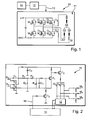
- the FIG. 1 shows a circuit diagram of an output stage 10 for a schematically illustrated electric motor 11 with the phases V, W, X.
- the phases V, W, X are each of Mosfets M1, M3, M5 with the supply voltage U or Mosfets M2, M4, M6 with Earth GND connected.
- the gates of the MOSFETs M1 to M6 are controlled by way of the gate line 13 shown in simplified form, which brings a signal level to each gate of the MOSFETs. Corresponding levels are output by the driver 12, which receives corresponding control signals from the microprocessor 14.
- FIG. 2 shows an additional electronics 15, which ensures a predetermined opening time, but slows down the kinetic energy of the rotor when returning to the starting position of the clutch by two or three phases of the electric motor are operated as a function of the induced voltage generator. If, for example, a reset signal is output by the microprocessor 14 via the line 16, the additional electronics 15 are activated by means of the transistor T 2 . At the motor terminals U u and U w , the voltage of the windings is tapped and rectified by means of the diodes D 1 , D 2 , D 3 and D 4 , wherein the diodes D 2 and D 4 already as in FIG. 1 already shown as diodes D2 and D4 are included in the mosfets.
- This rectified voltage is limited by means of the zener diode D z .
- the voltage signal is filtered by means of the resistors R 1 , R 2 and R 3 which are correspondingly switched into the circuit and which are connected in parallel with the capacitor C 1 .
- the resistors R 1 , R 2 and R 3 simultaneously form a voltage divider for matching the measured induced voltage to the base of the transistor T 1 . This switches in response to the rotational speed of the rotor as a result of the resulting induced voltage in the windings of the electric motor, the transistor T 3 , the gate voltages of the mosfets M2, M4 and M6 switches.
- FIG. 3 shows an embodiment of an additional electronics 15a, which differs from the additional electronics 15 of the figure in that no voltage source is generated from the induced voltage. It is assumed that the supply voltage U is present at the driver 12 and is fed via the line 7 into the additional electronics 15a. Should the supply voltage U in the driver nevertheless fail, a capacitor C 2 charged during normal operation can take over the voltage supply for the time required to decelerate the rotor. Opposite the FIG. 1 In particular, the transistor T 3 and the tuned him omitted.
- a level preset is provided between the microprocessor 12 and the driver 12, in which by means of pull-up or PullDown resistors during a reset, the levels for the MOSFETs M 2 , M 4 and M 6 are set to be switched while the levels for the remaining MOSFETs (see FIG. 1 ) are high impedance.
- the non-detailed described component names correspond to those of FIG. 1 ,
Landscapes
- Physics & Mathematics (AREA)
- Engineering & Computer Science (AREA)
- General Engineering & Computer Science (AREA)
- Electromagnetism (AREA)
- Fluid Mechanics (AREA)
- Mechanical Engineering (AREA)
- Control Of Motors That Do Not Use Commutators (AREA)
- General Electrical Machinery Utilizing Piezoelectricity, Electrostriction Or Magnetostriction (AREA)
- Connection Of Motors, Electrical Generators, Mechanical Devices, And The Like (AREA)
- Mechanical Operated Clutches (AREA)
- Hydraulic Clutches, Magnetic Clutches, Fluid Clutches, And Fluid Joints (AREA)
Abstract
Description
- Die Erfindung betrifft einen elektrisch betriebenen Kupplungsaktor mit einem auf eine Kupplung einwirkenden, von einem Rotor eines Elektromotors angetriebenen Betätigungselement.
- Kupplungsaktoren für Kupplungen, die elektrisch mittels eines Elektromotors betätigt werden, sind bekannt. Die
DE 10 2006 043 330 A1 zeigt ein Beispiel eines so genannten Hebeleinrückers, bei dem ein Betätigungsglied in Form eines Hebels von einer von einem Elektromotor angetriebenen Rolleneinheit axial verlagert wird und damit eine Kupplung entgegen einer Rückstellkraft eingerückt wird. - Wird die Spannung am Elektromotor abgeschaltet, beispielsweise weil an dem den Elektromotor steuernden Steuergerät die Versorgungsleitung unterbrochen wird oder die Steuerung selbst einen Reset verursacht, wird die Kupplung durch die fehlende Hemmung des Betätigungsgliedes durch den Elektromotor unter Wirkung der Rückstellkraft geöffnet. Durch diese Rückstellkräfte kehrt der Kupplungsaktor in einen kraftfreien Zustand, der durch einen Anschlag definiert sein kann zurück.
- Aufgabe der vorliegenden Anmeldung ist die Verbesserung derartiger Kupplungsaktoren insbesondere bezüglich ihres Komfort und ihrer Langzeitbeständigkeit. Dabei soll eine Verbesserung ohne hohe Kosten und insbesondere ohne großen zusätzlichen Aufwand an mechanischen, vorzugsweise bewegten Bauteilen erfolgen.
- Die Aufgabe wird durch einen elektrisch betriebenen Kupplungsaktor mit einem auf eine Kupplung einwirkenden, von einem Rotor eines Elektromotors angetriebenen Betätigungselement gelöst, wobei der Kupplungsaktor im nicht angetriebenen Zustand durch Rückstellkräfte der Kupplung an einen Anschlag bewegt wird und die Drehzahl des Rotors durch einen generatorischen Betrieb des Elektromotors im nicht angetriebenen Zustand in Abhängigkeit von der durch den generatorischen Betrieb induzierten Spannung vermindert wird.
- Als Kupplungsaktoren eignen sich dabei alle Kupplungsaktoren, die während einer Betätigung durch einen Elektromotor entgegen einer Kraft geschlossen oder geöffnet werden und in diesem Zustand mittels einer vom Elektromotor aufgewendeten Kraft gehalten werden. Wird der Elektromotor anschließend mit einer geringeren als der zum Halten des Kupplungszustands notwendigen Energie bestromt, kehrt die Kupplung wieder kontrolliert in den entspannten Zustand zurück. Insbesondere sind erfindungsgemäße Kupplungsaktoren für so genannte Doppelkupplungsgetriebe vorteilhaft, die zwangsweise zugedrückt oder zugezogen werden und die nach Abschalten oder einem Ausfall der Versorgungsspannung selbstständig in den geöffneten Zustand zurückkehren, um ein Verblocken des Getriebes bei einem Reibschluss beider Kupplungen zu vermeiden.
- In besonders vorteilhafter Weise wird durch die Erfindung das schnelle Öffnen der Kupplung und ein damit verbundener harter Anschlag von in den Ausgangszustand zurückkehrenden Kupplungsbauteilen vermieden. Derartige Bauteile können beispielsweise Bauteile eines Drehantriebs wie Spindeln, Spindelmutter, Lager und Rolleneinheiten sein, die bei einem sanften Anschlagen an einen Endanschlag des Kupplungsaktors entsprechend ausgelegt werden können und langzeitstabiler und weniger verschleißanfällig und ausfallsicherer werden.
- Unter einem generatorischen Betrieb kann eine Betriebsweise des Elektromotors verstanden werden, bei der zumindest eine Phase des Elektromotors so beschaltet wird, dass die infolge der Drehbeschleunigung des Rotors bei einer Rückbewegung des Betätigungsglieds des Kupplungsaktors entstehende Induktionsenergie abgebaut und damit der Rotor gebremst wird. Dabei ist unter dem Begriff einer Phase des Elektromotors jede mechanische Form eines Motors erfasst, die - entsprechend kommutiert - von einer Spannung beaufschlagt werden und eine entsprechend magnetische Funktion in einem Elektromotor erfüllen kann. Der Elektromotor kann daher in einer konventionellen Bauweise mit Wicklungen, wobei einer Phase mehrere parallel und/oder seriell geschaltete Wicklungen zugeordnet sein können, oder als Scheibenläufer ausgestaltet sein. Der Elektromotor kann mittels Bürsten kommutiert sein, besonders vorteilhaft ist die Verwendung einer elektronischen Kommutation. Die einzelnen Phasen werden von Treibern, die im Steuergerät errechnete Steuersignale über einen Signalausgang am Steuergerät mittels eines Signalpegels steuern, mit einer Versorgungsspannung beaufschlagt, wobei vorzugsweise Mosfets die Versorgungsspannungen vom Signalpegel abhängig durchschalten. Vorzugsweise kann ein elektronisch kommutierter Gleichstrommotor angewendet werden, dessen Leistung durch eine Pulsweitenmodulation steuerbar ist, indem eine Bestromung der Wicklungen mit einer Konstantspannung über zeitlich unterschiedlich lange Spannungspulse erfolgt.
- Der generatorische Betrieb wird erfindungsgemäß in Abhängigkeit von der induzierten Spannung eingeleitet. Beispielsweise wird ab einer vorgegebenen Grenzspannung der generatorische Betrieb aktiviert. Dabei hat es sich als vorteilhaft erwiesen, wenn die an einer Phase abgreifbare induzierte Spannung vor der Verwendung in einem Schaltkreis zur Schaltung des generatorischen Betriebszustands gleichgerichtet wird.
- In einem vorteilhaften Ausführungsbeispiel kann bei fehlender Versorgungsspannung ein Transistor in Abhängigkeit von der gleichgerichteten induzierten Spannung eine Eingangsspannung für einen zweiten Transistor, der die Gate-Spannung der Mosfets steuert, ausgeben. Auf diese Weise kann unabhängig von einer äußeren Versorgungsspannung die induktiv durch die Rotorbewegung erzeugte Spannung gleichzeitig die Speisung für eine Zusatzelektronik sein, die dafür sorgt, dass die Mosfets bei fehlender Versorgungsspannung so angesteuert werden, dass ein generatorischer Betrieb des Elektromotors erfolgt. Um eine derartige Zusatzelektronik dann auszuschalten, wenn die Steuerelektronik bei Anwesenheit einer Versorgungsspannung in normalem Betrieb elektromotorisch betrieben werden soll, kann ein weiterer Transistor verwendet werden, um die Wirkung der beiden Transistoren der Zusatzelektronik auszuschalten. Um zusätzlich einen negativen Effekt durch den Einfluss gegebenenfalls noch vorhandener Spannungen oder Restspannungen der Treiber auszuschalten, können diese bei fehlender Versorgungsspannung an ihrer Verbindung zu den Mosfets hochohmig geschaltet werden.
- Vorzugsweise werden nicht alle Phasen des Elektromotors in den generatorischen Betrieb geschaltet. Die Anzahl der zu schaltenden Phasen hängt insbesondere von der gewünschten Verzögerung der Drehzahl des Rotors ab. Weiterhin soll die Drehzahl nicht zu stark vermindert werden, da ansonsten die induzierte Spannung zusammenbrechen kann. Es hat sich als vorteilhaft erwiesen, wenn zwei bis vier, vorzugsweise zwei oder drei von vorzugsweise sechs Mosfets, die die Phasen steuern, in den generatorischen Betrieb geschaltet werden, das heißt kurzgeschlossen werden. Dabei kann an zumindest einer nicht geschalteten Phase die induzierte Spannung abgegriffen werden und in gewünschter Weise gleichgerichtet werden.
- In einem weiteren vorteilhaften Ausführungsbeispiel kann bei vorhandener Versorgungsspannung und einem Abschalten des Elektromotors durch einen Reset, indem die Treiber die Mosfets hochohmig schalten, zumindest ein Pegel an einem Ausgang des Treibers für eine entsprechende Wicklung wieder kurzgeschlossen werden, damit diese in den generatorischen Betrieb geschaltet wird. Ein derartiges Ausführungsbeispiel ist einfach aufgebaut, da die induzierte Spannung lediglich zur spannungsabhängigen Schaltung der Pegel verwendet werden muss. Zusätzlich kann, sofern eine zusätzliche Energieversorgung bei ebenfalls fehlender Versorgungsspannung, beispielsweise bei Unterbrechung der Versorgungsleitung, gewünscht ist, eine weitere Energiequelle vorgesehen sein, beispielsweise in Form eines Kondensators, der kurzzeitig die nötige elektrische Energie bereitstellt.
- Die Erfindung wird anhand der Figuren der
Figuren 1 bis 3 näher erläutert. Dabei zeigen: - Figur 1
- ein Schaltbild eines Ausführungsbeispiels einer Endstufe für einen Elektromotor eines Kupplungsaktors,
- Figur 2
- ein Schaltbild eines Ausführungsbeispiels für eine Zusatzelektronik zur Schaltung eines generatorischen Betriebs bei fehlender Versorgungsspannung
und - Figur 3
- ein Schaltbild eines Ausführungsbeispiels für eine Zusatzelektronik bei noch vorhandener Versorgungsspannung mit alternativer Spannungsversorgung.
- Die
Figur 1 zeigt ein Schaltbild einer Endstufe 10 für einen schematisch dargestellten Elektromotor 11 mit den Phasen V, W, X. Die Phasen V, W, X werden jeweils von Mosfets M1, M3, M5 mit der Versorgungsspannung U beziehungsweise von Mosfets M2, M4, M6 mit Erde GND verbunden. Die Dioden D1, D2, D3, D4, D5, D6, die in die Mosfets integriert sind, verhindern Fehlströme. Die Gates der Mosfets M1 bis M6 werden mittels über die vereinfacht dargestellte Gate-Leitung 13, die einen Signalpegel an jedes Gate der Mosfets heranführt, gesteuert. Entsprechende Pegel werden vom Treiber 12 ausgegeben, der entsprechende Steuersignale vom Mikroprozessor 14 erhält. Im Falle eines Ausfalls der Versorgungsspannung U, die auch den Mikroprozessor 14 und den Treiber 12 versorgt, werden alle Mosfets 6 hochohmig und der Elektromotor 11 kann die eingestellte Kupplungsposition eines nicht selbsthaltenden Kupplungsaktors nicht mehr halten. Die Kupplung kehrt in ihre Ausgangslage zurück und verdreht dabei über die mechanische Ankopplung des Elektromotors 11 an das Betätigungsglied den Rotor. Ein zeitlich unbegrenztes Kurzschließen der Wicklungen V, W, X mittels der Mosfets M2, M4, M6 würde zu einem unkontrollierten Abbremsen des Rotors führen und die Dynamikanforderung des Notöffnens wäre nicht mehr erfüllt. Vielmehr könnte der Kupplungsaktor an einer unvorhergesehenen Position zum Stillstand kommen, bei dem die Kupplung noch nicht den Ausgangszustand erreicht hat. -
Figur 2 zeigt eine Zusatzelektronik 15, die eine vorgegebene Öffnungszeit gewährleistet, die aber die kinetische Energie des Rotor beim Zurückfahren in die Ausgangsposition der Kupplung abbremst, indem zwei oder drei Phasen des Elektromotors generatorisch in Abhängigkeit von der induzierten Spannung betrieben werden. Wird beispielsweise von dem Mikroprozessor 14 über die Leitung 16 ein Reset-Signal ausgegeben, wird mittels des Transistors T2 die Zusatzelektronik 15 aktiviert. An den Motorklemmen Uu und Uw wird die Spannung der Wicklungen abgegriffen und mittels der Dioden D1, D2, D3 und D4 gleichgerichtet, wobei die Dioden D2 und D4 bereits wie inFigur 1 gezeigt bereits als Dioden D2 und D4 in den Mosfets enthalten sind. Diese gleichgerichtete Spannung wird mittels der Zener-Diode Dz begrenzt. Eine Filterung des Spannungssignals erfolgt mittels der in den Schaltkreis entsprechend eingeschalteten Widerstände R1, R2 und R3, der zu dem Kondensator C1 parallel geschaltet ist. Die Widerstände R1, R2 und R3 bilden gleichzeitig einen Spannungsteiler zur Anpassung der gemessenen induzierten Spannung an die Basis des Transistors T1. Dieser schaltet in Abhängigkeit der Drehzahl des Rotors infolge der sich ergebenden induzierten Spannung in den Wicklungen des Elektromotors den Transistor T3, die Gate-Spannungen der Mosfets M2, M4 und M6 schaltet. EntsprechendFigur 1 werden diese und dem folgend die Wicklungen niederohmig geschaltet und bremsen infolge des generatorischen Moments den Rotor und damit das mit diesem wirksam mechanisch verbundene Betätigungsglied gegen die entstehenden Rückstellkräfte ab. Der ebenfalls mit den Gates der Mosfets verbundene Treiber 12 ist während eines Resets hochohmig. Die Dioden D5, D6, und D7 sperren im die Zusatzelektronik 15 gegen eine Einwirkung des Treibers 12. Die gleichgerichtete induzierte Spannung dient gleichzeitig als Spannungsquelle für die Zusatzelektronik. Die übrigen ohne Bezeichnung dargestellten elektronischen Symbole entsprechen einer bekannten Auslegung einer Halbleiterschaltung. - Die
Figur 3 zeigt ein Ausführungsbeispiel einer Zusatzelektronik 15a, die sich von der Zusatzelektronik 15 der Figur dadurch unterscheidet, dass aus der induzierten Spannung keine Spannungsquelle generiert wird. Es wird davon ausgegangen, dass die Versorgungsspannung U am Treiber 12 vorhanden ist und über die Leitung 7 in die Zusatzelektronik 15a eingespeist wird. Sollte die Versorgungsspannung U im Treiber dennoch ausfallen, kann ein während des Normalbetriebs aufgeladener Kondensator C2 für die zum Verzögern des Rotors notwendige Zeit die Spannungsversorgung übernehmen. Gegenüber derFigur 1 können insbesondere der Transistor T3 und die ihn abstimmenden entfallen. Zusätzlich ist zwischen dem Mikroprozessor 12 und dem Treiber 12 eine Pegelvorgabe vorgesehen, in der mittels PullUp- oder PullDown-Widerständen während eines Resets die Pegel für die Mosfets M2, M4 und M6 so eingestellt sind, dass sie geschaltet sind, während die Pegel für die übrigen Mosfets (sieheFigur 1 ) hochohmig sind. Die nicht detailiert beschriebenen Bauteilbezeichnungen entsprechen denen derFigur 1 . -
10 Endstufe D5 Diode 11 Elektromotor D6 Diode 12 Treiber Dz Zener-Diode 13 Gate-Leitung GND Erde 14 Mikroprozessor M1 Mosfet 15 Zusatzelektronik M2 Mosfet 15a Zusatzelektronik M3 Mosfet 16 Leitung M4 Mosfet 17 Leitung M5 Mosfet 18 Pegelvorgabe M6 Mosfet C1 Kondensator R1 Widerstand C2 Kondensator R2 Widerstand D1 Diode R3 Widerstand D2 Diode T1 Transistor D2 Diode T2 Transistor D4 Diode T3 Transistor D5 Diode U Spannung D6 Diode Uu Klemmenspannung D1 Diode Uw Klemmenspannung D2 Diode V Wicklung D3 Diode W Wicklung D4 Diode X Wicklung
Claims (12)
- Elektrisch betriebener Kupplungsaktor mit einem auf eine Kupplung einwirkenden, von einem Rotor eines Elektromotors (11) angetriebenen Betätigungselement, wobei der Kupplungsaktor im nicht angetriebenen Zustand durch Rückstellkräfte der Kupplung an einen Anschlag bewegt wird, dadurch gekennzeichnet, dass die Drehzahl des Rotors durch einen generatorischen Betrieb des Elektromotors (11) im nicht angetriebenen Zustand in Abhängigkeit von der durch den generatorischen Betrieb induzierten Spannung vermindert wird.
- Elektrisch betriebener Kupplungsaktor nach Anspruch 1, dadurch gekennzeichnet, dass die induzierte Spannung gleichgerichtet wird.
- Elektrisch betriebener Kupplungsaktor nach Anspruch 1 oder 2, dadurch gekennzeichnet, dass in Abhängigkeit von der induzierten Spannung zumindest zwei Phasen (V, W, X) des Elektromotors (11) im generatorischen Betrieb kurzgeschlossen wird.
- Elektrisch betriebener Kupplungsaktor nach Anspruch 3, dadurch gekennzeichnet, dass jede Phase (V, W, X) mittels Mosfets (M1, M2, M3, M4, M5, M6) an eine Versorgungsspannung schaltbar ist.
- Elektrisch betriebener Kupplungsaktor nach einem der Ansprüche 1 bis 4, dadurch gekennzeichnet, dass der Elektromotor (11) ein Gleichstrommotor ist.
- Elektrisch betriebener Kupplungsaktor nach einem der Ansprüche 1 bis 5, dadurch gekennzeichnet, dass der Elektromotor (11) elektronisch kommutiert ist.
- Elektrisch betätigter Kupplungsaktor nach einem der Ansprüche 4 oder 6, dadurch gekennzeichnet, dass bei fehlender Versorgungsspannung ein Transistor (T1) in Abhängigkeit von der gleichgerichteten induzierten Spannung eine Eingangsspannung für einen zweiten Transistor (T3), der die Gate-Spannung der Mosfets (M1, M2, M3, M4, M5, M6) steuert, ausgibt.
- Elektrisch betätigter Kupplungsaktor nach Anspruch 7, dadurch gekennzeichnet, dass ein dritter Transistor (T2) bei Vorliegen der Versorgungsspannung die Wirkung der beiden anderen Transistoren (T1, T2) ausschaltet.
- Elektrisch betätigter Kupplungsaktor nach einem der Ansprüche 4 bis 8, dadurch gekennzeichnet, dass bei fehlender Versorgungsspannung der für die Versorgung der Mosfets (M1, M2, M3, M4, M5, M6) vorgesehene Treiber (12) hochohmig ist.
- Elektrisch betätigter Kupplungsaktor nach einem der Ansprüche 3 bis 9, dadurch gekennzeichnet, dass die induzierte Spannung an einer nicht kurzgeschlossenen Wicklung gemessen wird.
- Elektrisch betätigter Kupplungsaktor nach einem der Ansprüche 1 bis 5, dadurch gekennzeichnet, dass bei vorhandener Versorgungsspannung und einem Abschalten des Elektromotors durch einen Reset am Treiber (12) anliegende Pegel für die Mosfets (M2, M4, M6) niederohmig gesetzt werden, die im generatorischen Betrieb betrieben werden und die Pegel der übrigen Mosfets (M1, M3, M5) hochohmig gesetzt werden.
- Elektrisch betätigter Kupplungsaktor nach einem der Ansprüche 1 bis 11, dadurch gekennzeichnet, dass ein elektrischer Energiespeicher (C2) vorgesehen wird, der bei fehlender Versorgungsspannung eine Spannung zum Betrieb einer Zusatzelektronik (15a) zur Steuerung des generatorischen Betriebs des Elektromotors (11) während eines Resets bereitstellt.
Applications Claiming Priority (1)
| Application Number | Priority Date | Filing Date | Title |
|---|---|---|---|
| DE102007029937 | 2007-06-28 |
Publications (2)
| Publication Number | Publication Date |
|---|---|
| EP2009312A1 true EP2009312A1 (de) | 2008-12-31 |
| EP2009312B1 EP2009312B1 (de) | 2009-12-16 |
Family
ID=39846223
Family Applications (1)
| Application Number | Title | Priority Date | Filing Date |
|---|---|---|---|
| EP08010022A Not-in-force EP2009312B1 (de) | 2007-06-28 | 2008-06-02 | Elektrisch betriebener Kupplungsaktor |
Country Status (3)
| Country | Link |
|---|---|
| EP (1) | EP2009312B1 (de) |
| AT (1) | ATE452299T1 (de) |
| DE (2) | DE502008000251D1 (de) |
Cited By (1)
| Publication number | Priority date | Publication date | Assignee | Title |
|---|---|---|---|---|
| WO2017162771A1 (de) * | 2016-03-24 | 2017-09-28 | GETRAG B.V. & Co. KG | Verfahren und anordnung zum betätigen einer antriebsstrangkomponente |
Citations (4)
| Publication number | Priority date | Publication date | Assignee | Title |
|---|---|---|---|---|
| GB2256021A (en) * | 1991-04-19 | 1992-11-25 | Mitsubishi Electric Corp | Vehicle electromagnetic clutch control device |
| DE102006001468A1 (de) * | 2005-02-05 | 2006-08-10 | Luk Lamellen Und Kupplungsbau Beteiligungs Kg | Vorrichtung und Verfahren zum Verstellen einer in einem Antriebsstrang eines Kraftfahrzeugs angeordneten Kupplung |
| DE102006043330A1 (de) | 2005-09-29 | 2007-04-05 | Luk Lamellen Und Kupplungsbau Beteiligungs Kg | Hebelsystem |
| US20070135260A1 (en) * | 2005-12-09 | 2007-06-14 | Omfb S.P.A. Hydraulic Components | Solenoid Device for Engaging Power Takeoffs |
-
2008
- 2008-06-02 AT AT08010022T patent/ATE452299T1/de active
- 2008-06-02 EP EP08010022A patent/EP2009312B1/de not_active Not-in-force
- 2008-06-02 DE DE502008000251T patent/DE502008000251D1/de active Active
- 2008-06-02 DE DE102008026422A patent/DE102008026422A1/de not_active Withdrawn
Patent Citations (4)
| Publication number | Priority date | Publication date | Assignee | Title |
|---|---|---|---|---|
| GB2256021A (en) * | 1991-04-19 | 1992-11-25 | Mitsubishi Electric Corp | Vehicle electromagnetic clutch control device |
| DE102006001468A1 (de) * | 2005-02-05 | 2006-08-10 | Luk Lamellen Und Kupplungsbau Beteiligungs Kg | Vorrichtung und Verfahren zum Verstellen einer in einem Antriebsstrang eines Kraftfahrzeugs angeordneten Kupplung |
| DE102006043330A1 (de) | 2005-09-29 | 2007-04-05 | Luk Lamellen Und Kupplungsbau Beteiligungs Kg | Hebelsystem |
| US20070135260A1 (en) * | 2005-12-09 | 2007-06-14 | Omfb S.P.A. Hydraulic Components | Solenoid Device for Engaging Power Takeoffs |
Cited By (1)
| Publication number | Priority date | Publication date | Assignee | Title |
|---|---|---|---|---|
| WO2017162771A1 (de) * | 2016-03-24 | 2017-09-28 | GETRAG B.V. & Co. KG | Verfahren und anordnung zum betätigen einer antriebsstrangkomponente |
Also Published As
| Publication number | Publication date |
|---|---|
| ATE452299T1 (de) | 2010-01-15 |
| EP2009312B1 (de) | 2009-12-16 |
| DE102008026422A1 (de) | 2009-01-08 |
| DE502008000251D1 (de) | 2010-01-28 |
Similar Documents
| Publication | Publication Date | Title |
|---|---|---|
| DE102017107078A1 (de) | Elektrowerkzeug und Motortreibersystem davon | |
| DE112019001048T5 (de) | Motorantriebssteuervorrichtung und motorantriebssteuerverfahren | |
| EP4226065B1 (de) | Parksperreneinrichtung für ein fahrzeug und verfahren zum betreiben einer parksperreneinrichtung in einem fahrzeug | |
| EP1203443B1 (de) | Verfahren zur steuerung eines elektrischen antriebsmotors eines kraftfahreug-verstellantriebes | |
| EP2009312B1 (de) | Elektrisch betriebener Kupplungsaktor | |
| DE3811799A1 (de) | Schaltungsanordnung zum bidirektionalen ansteuern von gleichstrommotoren oder gleichstromstellgliedern | |
| DE4201005C2 (de) | Schaltungsanordnung zum netzunabhängigen, aussetzerfreien Bremsen eines Reihenschlußmotors | |
| EP3673133A1 (de) | Antriebsvorrichtung für eine fahrzeugklappe | |
| AT403866B (de) | Schaltungsanordnung zum abbremsen eines stromwendermotors, insbesondere eines universalmotors in einem elektrowerkzeug | |
| DE102014116689A1 (de) | Vorrichtung und Verfahren zum Sichern einer Antriebssteuerung gegen Versorgungsspannungsausfälle | |
| DE3128787A1 (de) | "elektrisch betaetigbare schaltvorrichtung zur umschaltung einer mit verschiedenen drehzahlen antreibbaren triebwelle" | |
| EP1911146A1 (de) | Elektromotor | |
| DE102017204091A1 (de) | Schaltvorrichtung zum Schalten eines elektrischen Erregerstroms für eine elektrische Maschine mit einem Läufer | |
| WO1997048177A1 (de) | Anordnung mit einem elektronisch kommutierten motor | |
| DE102004013108B4 (de) | Verfahren zum Betreiben einer Versorgungseinheit für eine Treiberschaltung sowie Versorgungseinheit für eine Treiberschaltung | |
| EP1044921A2 (de) | Antrieb mit einer Steuerung für ein Hubwerk eines Hebezeuges, insbesondere ein kleinbauendes Hebezeug | |
| EP2115847A1 (de) | Kraftfahrzeug-steuergerät mit verpolschutz | |
| DE10254608A1 (de) | Antriebssystem | |
| DE10226152A1 (de) | Schaltungsanordnung zum Betreiben eines Gleichstrommotors und Verstelleinrichtung mit einer solchen | |
| DE102017114316A1 (de) | Verfahren zur Vermeidung oder Verzögerung eines Kurzschlusses bei einem Elektromotor | |
| EP2162979A2 (de) | Ansteuereinrichtung für einen elektromotor | |
| EP3426956B1 (de) | Ventilantrieb | |
| EP4002677B1 (de) | Türsystem für ein fahrzeug mit einem türflügel und verfahren zum selektiven abbremsen eines elektrisch antreibbaren türflügels | |
| DE102004041466B4 (de) | Elektromotorischer Stellantrieb mit Steuereinheit für Zwischenposition und Steuerverfahren | |
| WO2023202810A1 (de) | Verfahren zur energieabsorption in einem elektrischen antriebssystem und elektrisches antriebssystem |
Legal Events
| Date | Code | Title | Description |
|---|---|---|---|
| PUAI | Public reference made under article 153(3) epc to a published international application that has entered the european phase |
Free format text: ORIGINAL CODE: 0009012 |
|
| AK | Designated contracting states |
Kind code of ref document: A1 Designated state(s): AT BE BG CH CY CZ DE DK EE ES FI FR GB GR HR HU IE IS IT LI LT LU LV MC MT NL NO PL PT RO SE SI SK TR |
|
| AX | Request for extension of the european patent |
Extension state: AL BA MK RS |
|
| 17P | Request for examination filed |
Effective date: 20090630 |
|
| GRAP | Despatch of communication of intention to grant a patent |
Free format text: ORIGINAL CODE: EPIDOSNIGR1 |
|
| AKX | Designation fees paid |
Designated state(s): AT BE BG CH CY CZ DE DK EE ES FI FR GB GR HR HU IE IS IT LI LT LU LV MC MT NL NO PL PT RO SE SI SK TR |
|
| GRAS | Grant fee paid |
Free format text: ORIGINAL CODE: EPIDOSNIGR3 |
|
| GRAA | (expected) grant |
Free format text: ORIGINAL CODE: 0009210 |
|
| AK | Designated contracting states |
Kind code of ref document: B1 Designated state(s): AT BE BG CH CY CZ DE DK EE ES FI FR GB GR HR HU IE IS IT LI LT LU LV MC MT NL NO PL PT RO SE SI SK TR |
|
| REG | Reference to a national code |
Ref country code: GB Ref legal event code: FG4D Free format text: NOT ENGLISH |
|
| REG | Reference to a national code |
Ref country code: CH Ref legal event code: EP |
|
| REG | Reference to a national code |
Ref country code: IE Ref legal event code: FG4D |
|
| REF | Corresponds to: |
Ref document number: 502008000251 Country of ref document: DE Date of ref document: 20100128 Kind code of ref document: P |
|
| REG | Reference to a national code |
Ref country code: NL Ref legal event code: VDEP Effective date: 20091216 |
|
| PG25 | Lapsed in a contracting state [announced via postgrant information from national office to epo] |
Ref country code: LT Free format text: LAPSE BECAUSE OF FAILURE TO SUBMIT A TRANSLATION OF THE DESCRIPTION OR TO PAY THE FEE WITHIN THE PRESCRIBED TIME-LIMIT Effective date: 20091216 Ref country code: FI Free format text: LAPSE BECAUSE OF FAILURE TO SUBMIT A TRANSLATION OF THE DESCRIPTION OR TO PAY THE FEE WITHIN THE PRESCRIBED TIME-LIMIT Effective date: 20091216 Ref country code: NO Free format text: LAPSE BECAUSE OF FAILURE TO SUBMIT A TRANSLATION OF THE DESCRIPTION OR TO PAY THE FEE WITHIN THE PRESCRIBED TIME-LIMIT Effective date: 20100316 Ref country code: SE Free format text: LAPSE BECAUSE OF FAILURE TO SUBMIT A TRANSLATION OF THE DESCRIPTION OR TO PAY THE FEE WITHIN THE PRESCRIBED TIME-LIMIT Effective date: 20091216 |
|
| LTIE | Lt: invalidation of european patent or patent extension |
Effective date: 20091216 |
|
| PG25 | Lapsed in a contracting state [announced via postgrant information from national office to epo] |
Ref country code: SI Free format text: LAPSE BECAUSE OF FAILURE TO SUBMIT A TRANSLATION OF THE DESCRIPTION OR TO PAY THE FEE WITHIN THE PRESCRIBED TIME-LIMIT Effective date: 20091216 Ref country code: PL Free format text: LAPSE BECAUSE OF FAILURE TO SUBMIT A TRANSLATION OF THE DESCRIPTION OR TO PAY THE FEE WITHIN THE PRESCRIBED TIME-LIMIT Effective date: 20091216 Ref country code: LV Free format text: LAPSE BECAUSE OF FAILURE TO SUBMIT A TRANSLATION OF THE DESCRIPTION OR TO PAY THE FEE WITHIN THE PRESCRIBED TIME-LIMIT Effective date: 20091216 Ref country code: HR Free format text: LAPSE BECAUSE OF FAILURE TO SUBMIT A TRANSLATION OF THE DESCRIPTION OR TO PAY THE FEE WITHIN THE PRESCRIBED TIME-LIMIT Effective date: 20091216 |
|
| REG | Reference to a national code |
Ref country code: IE Ref legal event code: FD4D |
|
| PG25 | Lapsed in a contracting state [announced via postgrant information from national office to epo] |
Ref country code: ES Free format text: LAPSE BECAUSE OF FAILURE TO SUBMIT A TRANSLATION OF THE DESCRIPTION OR TO PAY THE FEE WITHIN THE PRESCRIBED TIME-LIMIT Effective date: 20100327 Ref country code: RO Free format text: LAPSE BECAUSE OF FAILURE TO SUBMIT A TRANSLATION OF THE DESCRIPTION OR TO PAY THE FEE WITHIN THE PRESCRIBED TIME-LIMIT Effective date: 20091216 Ref country code: IS Free format text: LAPSE BECAUSE OF FAILURE TO SUBMIT A TRANSLATION OF THE DESCRIPTION OR TO PAY THE FEE WITHIN THE PRESCRIBED TIME-LIMIT Effective date: 20100416 Ref country code: NL Free format text: LAPSE BECAUSE OF FAILURE TO SUBMIT A TRANSLATION OF THE DESCRIPTION OR TO PAY THE FEE WITHIN THE PRESCRIBED TIME-LIMIT Effective date: 20091216 Ref country code: EE Free format text: LAPSE BECAUSE OF FAILURE TO SUBMIT A TRANSLATION OF THE DESCRIPTION OR TO PAY THE FEE WITHIN THE PRESCRIBED TIME-LIMIT Effective date: 20091216 Ref country code: IE Free format text: LAPSE BECAUSE OF FAILURE TO SUBMIT A TRANSLATION OF THE DESCRIPTION OR TO PAY THE FEE WITHIN THE PRESCRIBED TIME-LIMIT Effective date: 20091216 Ref country code: BG Free format text: LAPSE BECAUSE OF FAILURE TO SUBMIT A TRANSLATION OF THE DESCRIPTION OR TO PAY THE FEE WITHIN THE PRESCRIBED TIME-LIMIT Effective date: 20100316 |
|
| PG25 | Lapsed in a contracting state [announced via postgrant information from national office to epo] |
Ref country code: CZ Free format text: LAPSE BECAUSE OF FAILURE TO SUBMIT A TRANSLATION OF THE DESCRIPTION OR TO PAY THE FEE WITHIN THE PRESCRIBED TIME-LIMIT Effective date: 20091216 Ref country code: SK Free format text: LAPSE BECAUSE OF FAILURE TO SUBMIT A TRANSLATION OF THE DESCRIPTION OR TO PAY THE FEE WITHIN THE PRESCRIBED TIME-LIMIT Effective date: 20091216 |
|
| RAP2 | Party data changed (patent owner data changed or rights of a patent transferred) |
Owner name: SCHAEFFLER TECHNOLOGIES GMBH & CO. KG |
|
| PLBE | No opposition filed within time limit |
Free format text: ORIGINAL CODE: 0009261 |
|
| STAA | Information on the status of an ep patent application or granted ep patent |
Free format text: STATUS: NO OPPOSITION FILED WITHIN TIME LIMIT |
|
| PG25 | Lapsed in a contracting state [announced via postgrant information from national office to epo] |
Ref country code: CY Free format text: LAPSE BECAUSE OF FAILURE TO SUBMIT A TRANSLATION OF THE DESCRIPTION OR TO PAY THE FEE WITHIN THE PRESCRIBED TIME-LIMIT Effective date: 20091216 Ref country code: GR Free format text: LAPSE BECAUSE OF FAILURE TO SUBMIT A TRANSLATION OF THE DESCRIPTION OR TO PAY THE FEE WITHIN THE PRESCRIBED TIME-LIMIT Effective date: 20100317 |
|
| 26N | No opposition filed |
Effective date: 20100917 |
|
| BERE | Be: lapsed |
Owner name: LUK LAMELLEN UND KUPPLUNGSBAU BETEILIGUNGS K.G. Effective date: 20100630 |
|
| PG25 | Lapsed in a contracting state [announced via postgrant information from national office to epo] |
Ref country code: DK Free format text: LAPSE BECAUSE OF FAILURE TO SUBMIT A TRANSLATION OF THE DESCRIPTION OR TO PAY THE FEE WITHIN THE PRESCRIBED TIME-LIMIT Effective date: 20091216 Ref country code: MC Free format text: LAPSE BECAUSE OF NON-PAYMENT OF DUE FEES Effective date: 20100630 |
|
| PG25 | Lapsed in a contracting state [announced via postgrant information from national office to epo] |
Ref country code: IT Free format text: LAPSE BECAUSE OF FAILURE TO SUBMIT A TRANSLATION OF THE DESCRIPTION OR TO PAY THE FEE WITHIN THE PRESCRIBED TIME-LIMIT Effective date: 20091216 |
|
| PG25 | Lapsed in a contracting state [announced via postgrant information from national office to epo] |
Ref country code: MT Free format text: LAPSE BECAUSE OF FAILURE TO SUBMIT A TRANSLATION OF THE DESCRIPTION OR TO PAY THE FEE WITHIN THE PRESCRIBED TIME-LIMIT Effective date: 20091216 |
|
| PG25 | Lapsed in a contracting state [announced via postgrant information from national office to epo] |
Ref country code: BE Free format text: LAPSE BECAUSE OF NON-PAYMENT OF DUE FEES Effective date: 20100630 |
|
| PG25 | Lapsed in a contracting state [announced via postgrant information from national office to epo] |
Ref country code: PT Free format text: LAPSE BECAUSE OF FAILURE TO SUBMIT A TRANSLATION OF THE DESCRIPTION OR TO PAY THE FEE WITHIN THE PRESCRIBED TIME-LIMIT Effective date: 20100516 Ref country code: HU Free format text: LAPSE BECAUSE OF FAILURE TO SUBMIT A TRANSLATION OF THE DESCRIPTION OR TO PAY THE FEE WITHIN THE PRESCRIBED TIME-LIMIT Effective date: 20100617 Ref country code: LU Free format text: LAPSE BECAUSE OF NON-PAYMENT OF DUE FEES Effective date: 20100602 |
|
| REG | Reference to a national code |
Ref country code: DE Ref legal event code: R081 Ref document number: 502008000251 Country of ref document: DE Owner name: SCHAEFFLER TECHNOLOGIES AG & CO. KG, DE Free format text: FORMER OWNER: SCHAEFFLER TECHNOLOGIES GMBH & CO. KG, 91074 HERZOGENAURACH, DE Effective date: 20120828 Ref country code: DE Ref legal event code: R081 Ref document number: 502008000251 Country of ref document: DE Owner name: SCHAEFFLER TECHNOLOGIES GMBH & CO. KG, DE Free format text: FORMER OWNER: SCHAEFFLER TECHNOLOGIES GMBH & CO. KG, 91074 HERZOGENAURACH, DE Effective date: 20120828 |
|
| PG25 | Lapsed in a contracting state [announced via postgrant information from national office to epo] |
Ref country code: TR Free format text: LAPSE BECAUSE OF FAILURE TO SUBMIT A TRANSLATION OF THE DESCRIPTION OR TO PAY THE FEE WITHIN THE PRESCRIBED TIME-LIMIT Effective date: 20091216 |
|
| REG | Reference to a national code |
Ref country code: CH Ref legal event code: PL |
|
| REG | Reference to a national code |
Ref country code: CH Ref legal event code: PL |
|
| GBPC | Gb: european patent ceased through non-payment of renewal fee |
Effective date: 20120602 |
|
| PG25 | Lapsed in a contracting state [announced via postgrant information from national office to epo] |
Ref country code: CH Free format text: LAPSE BECAUSE OF NON-PAYMENT OF DUE FEES Effective date: 20120630 Ref country code: LI Free format text: LAPSE BECAUSE OF NON-PAYMENT OF DUE FEES Effective date: 20120630 Ref country code: GB Free format text: LAPSE BECAUSE OF NON-PAYMENT OF DUE FEES Effective date: 20120602 |
|
| REG | Reference to a national code |
Ref country code: DE Ref legal event code: R081 Ref document number: 502008000251 Country of ref document: DE Owner name: SCHAEFFLER TECHNOLOGIES AG CO. KG, DE Free format text: FORMER OWNER: SCHAEFFLER TECHNOLOGIES AG CO. KG, 91074 HERZOGENAURACH, DE Effective date: 20140214 Ref country code: DE Ref legal event code: R081 Ref document number: 502008000251 Country of ref document: DE Owner name: SCHAEFFLER TECHNOLOGIES AG & CO. KG, DE Free format text: FORMER OWNER: SCHAEFFLER TECHNOLOGIES AG & CO. KG, 91074 HERZOGENAURACH, DE Effective date: 20140214 Ref country code: DE Ref legal event code: R081 Ref document number: 502008000251 Country of ref document: DE Owner name: SCHAEFFLER TECHNOLOGIES GMBH & CO. KG, DE Free format text: FORMER OWNER: SCHAEFFLER TECHNOLOGIES AG & CO. KG, 91074 HERZOGENAURACH, DE Effective date: 20140214 |
|
| REG | Reference to a national code |
Ref country code: AT Ref legal event code: MM01 Ref document number: 452299 Country of ref document: AT Kind code of ref document: T Effective date: 20130602 |
|
| PG25 | Lapsed in a contracting state [announced via postgrant information from national office to epo] |
Ref country code: AT Free format text: LAPSE BECAUSE OF NON-PAYMENT OF DUE FEES Effective date: 20130602 |
|
| REG | Reference to a national code |
Ref country code: DE Ref legal event code: R081 Ref document number: 502008000251 Country of ref document: DE Owner name: SCHAEFFLER TECHNOLOGIES AG & CO. KG, DE Free format text: FORMER OWNER: SCHAEFFLER TECHNOLOGIES GMBH & CO. KG, 91074 HERZOGENAURACH, DE Effective date: 20150223 |
|
| REG | Reference to a national code |
Ref country code: FR Ref legal event code: PLFP Year of fee payment: 9 |
|
| REG | Reference to a national code |
Ref country code: FR Ref legal event code: PLFP Year of fee payment: 10 |
|
| REG | Reference to a national code |
Ref country code: FR Ref legal event code: PLFP Year of fee payment: 11 |
|
| PGFP | Annual fee paid to national office [announced via postgrant information from national office to epo] |
Ref country code: FR Payment date: 20180629 Year of fee payment: 11 |
|
| PGFP | Annual fee paid to national office [announced via postgrant information from national office to epo] |
Ref country code: DE Payment date: 20190830 Year of fee payment: 12 |
|
| PG25 | Lapsed in a contracting state [announced via postgrant information from national office to epo] |
Ref country code: FR Free format text: LAPSE BECAUSE OF NON-PAYMENT OF DUE FEES Effective date: 20190630 |
|
| REG | Reference to a national code |
Ref country code: DE Ref legal event code: R119 Ref document number: 502008000251 Country of ref document: DE |
|
| PG25 | Lapsed in a contracting state [announced via postgrant information from national office to epo] |
Ref country code: DE Free format text: LAPSE BECAUSE OF NON-PAYMENT OF DUE FEES Effective date: 20210101 |
|
| P01 | Opt-out of the competence of the unified patent court (upc) registered |
Effective date: 20230523 |