EP2009265A1 - Verbrennungsmotor - Google Patents
Verbrennungsmotor Download PDFInfo
- Publication number
- EP2009265A1 EP2009265A1 EP07254103A EP07254103A EP2009265A1 EP 2009265 A1 EP2009265 A1 EP 2009265A1 EP 07254103 A EP07254103 A EP 07254103A EP 07254103 A EP07254103 A EP 07254103A EP 2009265 A1 EP2009265 A1 EP 2009265A1
- Authority
- EP
- European Patent Office
- Prior art keywords
- engine
- compression
- catalytic converter
- internal combustion
- air
- Prior art date
- Legal status (The legal status is an assumption and is not a legal conclusion. Google has not performed a legal analysis and makes no representation as to the accuracy of the status listed.)
- Granted
Links
- 238000002485 combustion reaction Methods 0.000 title claims abstract description 62
- 230000003197 catalytic effect Effects 0.000 claims abstract description 58
- 238000011282 treatment Methods 0.000 claims abstract description 15
- 239000000446 fuel Substances 0.000 claims description 84
- QVGXLLKOCUKJST-UHFFFAOYSA-N atomic oxygen Chemical compound [O] QVGXLLKOCUKJST-UHFFFAOYSA-N 0.000 claims description 61
- 239000001301 oxygen Substances 0.000 claims description 61
- 229910052760 oxygen Inorganic materials 0.000 claims description 61
- 239000007789 gas Substances 0.000 claims description 44
- 238000011144 upstream manufacturing Methods 0.000 claims description 7
- 238000002347 injection Methods 0.000 claims description 5
- 239000007924 injection Substances 0.000 claims description 5
- 239000000470 constituent Substances 0.000 claims description 2
- MWUXSHHQAYIFBG-UHFFFAOYSA-N nitrogen oxide Inorganic materials O=[N] MWUXSHHQAYIFBG-UHFFFAOYSA-N 0.000 description 58
- CURLTUGMZLYLDI-UHFFFAOYSA-N Carbon dioxide Chemical compound O=C=O CURLTUGMZLYLDI-UHFFFAOYSA-N 0.000 description 20
- 229910002092 carbon dioxide Inorganic materials 0.000 description 11
- 239000001569 carbon dioxide Substances 0.000 description 10
- 229930195733 hydrocarbon Natural products 0.000 description 10
- 150000002430 hydrocarbons Chemical class 0.000 description 10
- UGFAIRIUMAVXCW-UHFFFAOYSA-N Carbon monoxide Chemical compound [O+]#[C-] UGFAIRIUMAVXCW-UHFFFAOYSA-N 0.000 description 9
- 229910002091 carbon monoxide Inorganic materials 0.000 description 9
- IJGRMHOSHXDMSA-UHFFFAOYSA-N Atomic nitrogen Chemical compound N#N IJGRMHOSHXDMSA-UHFFFAOYSA-N 0.000 description 8
- 238000006243 chemical reaction Methods 0.000 description 7
- 230000008901 benefit Effects 0.000 description 6
- 230000007423 decrease Effects 0.000 description 6
- 239000013618 particulate matter Substances 0.000 description 6
- 239000003502 gasoline Substances 0.000 description 5
- 230000004044 response Effects 0.000 description 5
- 230000001133 acceleration Effects 0.000 description 4
- 239000003054 catalyst Substances 0.000 description 4
- 239000000203 mixture Substances 0.000 description 4
- 229910052757 nitrogen Inorganic materials 0.000 description 4
- 230000001590 oxidative effect Effects 0.000 description 4
- 230000009467 reduction Effects 0.000 description 4
- 238000006722 reduction reaction Methods 0.000 description 4
- XLYOFNOQVPJJNP-UHFFFAOYSA-N water Substances O XLYOFNOQVPJJNP-UHFFFAOYSA-N 0.000 description 4
- 230000009286 beneficial effect Effects 0.000 description 3
- 238000005516 engineering process Methods 0.000 description 3
- 230000036541 health Effects 0.000 description 3
- 230000003647 oxidation Effects 0.000 description 3
- 238000007254 oxidation reaction Methods 0.000 description 3
- 230000008929 regeneration Effects 0.000 description 3
- 238000011069 regeneration method Methods 0.000 description 3
- 239000004071 soot Substances 0.000 description 3
- 238000009966 trimming Methods 0.000 description 3
- 239000006096 absorbing agent Substances 0.000 description 2
- 230000002411 adverse Effects 0.000 description 2
- 230000006835 compression Effects 0.000 description 2
- 238000007906 compression Methods 0.000 description 2
- 230000003247 decreasing effect Effects 0.000 description 2
- 230000000694 effects Effects 0.000 description 2
- VUZPPFZMUPKLLV-UHFFFAOYSA-N methane;hydrate Chemical compound C.O VUZPPFZMUPKLLV-UHFFFAOYSA-N 0.000 description 2
- 238000000034 method Methods 0.000 description 2
- 239000000523 sample Substances 0.000 description 2
- 231100000331 toxic Toxicity 0.000 description 2
- 230000002588 toxic effect Effects 0.000 description 2
- NINIDFKCEFEMDL-UHFFFAOYSA-N Sulfur Chemical compound [S] NINIDFKCEFEMDL-UHFFFAOYSA-N 0.000 description 1
- 239000005864 Sulphur Substances 0.000 description 1
- XSQUKJJJFZCRTK-UHFFFAOYSA-N Urea Chemical compound NC(N)=O XSQUKJJJFZCRTK-UHFFFAOYSA-N 0.000 description 1
- 238000003916 acid precipitation Methods 0.000 description 1
- 238000013459 approach Methods 0.000 description 1
- 239000006227 byproduct Substances 0.000 description 1
- 239000004202 carbamide Substances 0.000 description 1
- 238000010531 catalytic reduction reaction Methods 0.000 description 1
- 230000008859 change Effects 0.000 description 1
- 238000001816 cooling Methods 0.000 description 1
- 229910052878 cordierite Inorganic materials 0.000 description 1
- 238000003745 diagnosis Methods 0.000 description 1
- 238000010586 diagram Methods 0.000 description 1
- 239000002283 diesel fuel Substances 0.000 description 1
- JSKIRARMQDRGJZ-UHFFFAOYSA-N dimagnesium dioxido-bis[(1-oxido-3-oxo-2,4,6,8,9-pentaoxa-1,3-disila-5,7-dialuminabicyclo[3.3.1]nonan-7-yl)oxy]silane Chemical compound [Mg++].[Mg++].[O-][Si]([O-])(O[Al]1O[Al]2O[Si](=O)O[Si]([O-])(O1)O2)O[Al]1O[Al]2O[Si](=O)O[Si]([O-])(O1)O2 JSKIRARMQDRGJZ-UHFFFAOYSA-N 0.000 description 1
- 230000007613 environmental effect Effects 0.000 description 1
- 239000003344 environmental pollutant Substances 0.000 description 1
- 239000002803 fossil fuel Substances 0.000 description 1
- 239000005431 greenhouse gas Substances 0.000 description 1
- 230000004048 modification Effects 0.000 description 1
- 238000012986 modification Methods 0.000 description 1
- 238000004806 packaging method and process Methods 0.000 description 1
- 230000000737 periodic effect Effects 0.000 description 1
- 239000000047 product Substances 0.000 description 1
- HBMJWWWQQXIZIP-UHFFFAOYSA-N silicon carbide Chemical compound [Si+]#[C-] HBMJWWWQQXIZIP-UHFFFAOYSA-N 0.000 description 1
- 229910010271 silicon carbide Inorganic materials 0.000 description 1
- 239000000779 smoke Substances 0.000 description 1
- 238000011269 treatment regimen Methods 0.000 description 1
- 230000035899 viability Effects 0.000 description 1
Images


Classifications
-
- F—MECHANICAL ENGINEERING; LIGHTING; HEATING; WEAPONS; BLASTING
- F02—COMBUSTION ENGINES; HOT-GAS OR COMBUSTION-PRODUCT ENGINE PLANTS
- F02D—CONTROLLING COMBUSTION ENGINES
- F02D41/00—Electrical control of supply of combustible mixture or its constituents
- F02D41/0025—Controlling engines characterised by use of non-liquid fuels, pluralities of fuels, or non-fuel substances added to the combustible mixtures
- F02D41/0047—Controlling exhaust gas recirculation [EGR]
- F02D41/005—Controlling exhaust gas recirculation [EGR] according to engine operating conditions
- F02D41/0057—Specific combustion modes
-
- F—MECHANICAL ENGINEERING; LIGHTING; HEATING; WEAPONS; BLASTING
- F01—MACHINES OR ENGINES IN GENERAL; ENGINE PLANTS IN GENERAL; STEAM ENGINES
- F01N—GAS-FLOW SILENCERS OR EXHAUST APPARATUS FOR MACHINES OR ENGINES IN GENERAL; GAS-FLOW SILENCERS OR EXHAUST APPARATUS FOR INTERNAL COMBUSTION ENGINES
- F01N13/00—Exhaust or silencing apparatus characterised by constructional features ; Exhaust or silencing apparatus, or parts thereof, having pertinent characteristics not provided for in, or of interest apart from, groups F01N1/00 - F01N5/00, F01N9/00, F01N11/00
- F01N13/009—Exhaust or silencing apparatus characterised by constructional features ; Exhaust or silencing apparatus, or parts thereof, having pertinent characteristics not provided for in, or of interest apart from, groups F01N1/00 - F01N5/00, F01N9/00, F01N11/00 having two or more separate purifying devices arranged in series
- F01N13/0097—Exhaust or silencing apparatus characterised by constructional features ; Exhaust or silencing apparatus, or parts thereof, having pertinent characteristics not provided for in, or of interest apart from, groups F01N1/00 - F01N5/00, F01N9/00, F01N11/00 having two or more separate purifying devices arranged in series the purifying devices are arranged in a single housing
-
- F—MECHANICAL ENGINEERING; LIGHTING; HEATING; WEAPONS; BLASTING
- F01—MACHINES OR ENGINES IN GENERAL; ENGINE PLANTS IN GENERAL; STEAM ENGINES
- F01N—GAS-FLOW SILENCERS OR EXHAUST APPARATUS FOR MACHINES OR ENGINES IN GENERAL; GAS-FLOW SILENCERS OR EXHAUST APPARATUS FOR INTERNAL COMBUSTION ENGINES
- F01N3/00—Exhaust or silencing apparatus having means for purifying, rendering innocuous, or otherwise treating exhaust
- F01N3/02—Exhaust or silencing apparatus having means for purifying, rendering innocuous, or otherwise treating exhaust for cooling, or for removing solid constituents of, exhaust
- F01N3/021—Exhaust or silencing apparatus having means for purifying, rendering innocuous, or otherwise treating exhaust for cooling, or for removing solid constituents of, exhaust by means of filters
- F01N3/023—Exhaust or silencing apparatus having means for purifying, rendering innocuous, or otherwise treating exhaust for cooling, or for removing solid constituents of, exhaust by means of filters using means for regenerating the filters, e.g. by burning trapped particles
- F01N3/025—Exhaust or silencing apparatus having means for purifying, rendering innocuous, or otherwise treating exhaust for cooling, or for removing solid constituents of, exhaust by means of filters using means for regenerating the filters, e.g. by burning trapped particles using fuel burner or by adding fuel to exhaust
- F01N3/0253—Exhaust or silencing apparatus having means for purifying, rendering innocuous, or otherwise treating exhaust for cooling, or for removing solid constituents of, exhaust by means of filters using means for regenerating the filters, e.g. by burning trapped particles using fuel burner or by adding fuel to exhaust adding fuel to exhaust gases
-
- F—MECHANICAL ENGINEERING; LIGHTING; HEATING; WEAPONS; BLASTING
- F01—MACHINES OR ENGINES IN GENERAL; ENGINE PLANTS IN GENERAL; STEAM ENGINES
- F01N—GAS-FLOW SILENCERS OR EXHAUST APPARATUS FOR MACHINES OR ENGINES IN GENERAL; GAS-FLOW SILENCERS OR EXHAUST APPARATUS FOR INTERNAL COMBUSTION ENGINES
- F01N3/00—Exhaust or silencing apparatus having means for purifying, rendering innocuous, or otherwise treating exhaust
- F01N3/02—Exhaust or silencing apparatus having means for purifying, rendering innocuous, or otherwise treating exhaust for cooling, or for removing solid constituents of, exhaust
- F01N3/021—Exhaust or silencing apparatus having means for purifying, rendering innocuous, or otherwise treating exhaust for cooling, or for removing solid constituents of, exhaust by means of filters
- F01N3/033—Exhaust or silencing apparatus having means for purifying, rendering innocuous, or otherwise treating exhaust for cooling, or for removing solid constituents of, exhaust by means of filters in combination with other devices
- F01N3/035—Exhaust or silencing apparatus having means for purifying, rendering innocuous, or otherwise treating exhaust for cooling, or for removing solid constituents of, exhaust by means of filters in combination with other devices with catalytic reactors, e.g. catalysed diesel particulate filters
-
- F—MECHANICAL ENGINEERING; LIGHTING; HEATING; WEAPONS; BLASTING
- F01—MACHINES OR ENGINES IN GENERAL; ENGINE PLANTS IN GENERAL; STEAM ENGINES
- F01N—GAS-FLOW SILENCERS OR EXHAUST APPARATUS FOR MACHINES OR ENGINES IN GENERAL; GAS-FLOW SILENCERS OR EXHAUST APPARATUS FOR INTERNAL COMBUSTION ENGINES
- F01N3/00—Exhaust or silencing apparatus having means for purifying, rendering innocuous, or otherwise treating exhaust
- F01N3/08—Exhaust or silencing apparatus having means for purifying, rendering innocuous, or otherwise treating exhaust for rendering innocuous
- F01N3/10—Exhaust or silencing apparatus having means for purifying, rendering innocuous, or otherwise treating exhaust for rendering innocuous by thermal or catalytic conversion of noxious components of exhaust
- F01N3/101—Three-way catalysts
-
- F—MECHANICAL ENGINEERING; LIGHTING; HEATING; WEAPONS; BLASTING
- F01—MACHINES OR ENGINES IN GENERAL; ENGINE PLANTS IN GENERAL; STEAM ENGINES
- F01N—GAS-FLOW SILENCERS OR EXHAUST APPARATUS FOR MACHINES OR ENGINES IN GENERAL; GAS-FLOW SILENCERS OR EXHAUST APPARATUS FOR INTERNAL COMBUSTION ENGINES
- F01N3/00—Exhaust or silencing apparatus having means for purifying, rendering innocuous, or otherwise treating exhaust
- F01N3/08—Exhaust or silencing apparatus having means for purifying, rendering innocuous, or otherwise treating exhaust for rendering innocuous
- F01N3/10—Exhaust or silencing apparatus having means for purifying, rendering innocuous, or otherwise treating exhaust for rendering innocuous by thermal or catalytic conversion of noxious components of exhaust
- F01N3/18—Exhaust or silencing apparatus having means for purifying, rendering innocuous, or otherwise treating exhaust for rendering innocuous by thermal or catalytic conversion of noxious components of exhaust characterised by methods of operation; Control
- F01N3/20—Exhaust or silencing apparatus having means for purifying, rendering innocuous, or otherwise treating exhaust for rendering innocuous by thermal or catalytic conversion of noxious components of exhaust characterised by methods of operation; Control specially adapted for catalytic conversion ; Methods of operation or control of catalytic converters
- F01N3/2006—Periodically heating or cooling catalytic reactors, e.g. at cold starting or overheating
- F01N3/2033—Periodically heating or cooling catalytic reactors, e.g. at cold starting or overheating using a fuel burner or introducing fuel into exhaust duct
-
- F—MECHANICAL ENGINEERING; LIGHTING; HEATING; WEAPONS; BLASTING
- F02—COMBUSTION ENGINES; HOT-GAS OR COMBUSTION-PRODUCT ENGINE PLANTS
- F02D—CONTROLLING COMBUSTION ENGINES
- F02D41/00—Electrical control of supply of combustible mixture or its constituents
- F02D41/0002—Controlling intake air
-
- F—MECHANICAL ENGINEERING; LIGHTING; HEATING; WEAPONS; BLASTING
- F02—COMBUSTION ENGINES; HOT-GAS OR COMBUSTION-PRODUCT ENGINE PLANTS
- F02D—CONTROLLING COMBUSTION ENGINES
- F02D41/00—Electrical control of supply of combustible mixture or its constituents
- F02D41/30—Controlling fuel injection
- F02D41/3011—Controlling fuel injection according to or using specific or several modes of combustion
- F02D41/3017—Controlling fuel injection according to or using specific or several modes of combustion characterised by the mode(s) being used
- F02D41/3035—Controlling fuel injection according to or using specific or several modes of combustion characterised by the mode(s) being used a mode being the premixed charge compression-ignition mode
-
- F—MECHANICAL ENGINEERING; LIGHTING; HEATING; WEAPONS; BLASTING
- F01—MACHINES OR ENGINES IN GENERAL; ENGINE PLANTS IN GENERAL; STEAM ENGINES
- F01N—GAS-FLOW SILENCERS OR EXHAUST APPARATUS FOR MACHINES OR ENGINES IN GENERAL; GAS-FLOW SILENCERS OR EXHAUST APPARATUS FOR INTERNAL COMBUSTION ENGINES
- F01N2250/00—Combinations of different methods of purification
- F01N2250/02—Combinations of different methods of purification filtering and catalytic conversion
-
- F—MECHANICAL ENGINEERING; LIGHTING; HEATING; WEAPONS; BLASTING
- F01—MACHINES OR ENGINES IN GENERAL; ENGINE PLANTS IN GENERAL; STEAM ENGINES
- F01N—GAS-FLOW SILENCERS OR EXHAUST APPARATUS FOR MACHINES OR ENGINES IN GENERAL; GAS-FLOW SILENCERS OR EXHAUST APPARATUS FOR INTERNAL COMBUSTION ENGINES
- F01N2560/00—Exhaust systems with means for detecting or measuring exhaust gas components or characteristics
- F01N2560/02—Exhaust systems with means for detecting or measuring exhaust gas components or characteristics the means being an exhaust gas sensor
- F01N2560/025—Exhaust systems with means for detecting or measuring exhaust gas components or characteristics the means being an exhaust gas sensor for measuring or detecting O2, e.g. lambda sensors
-
- F—MECHANICAL ENGINEERING; LIGHTING; HEATING; WEAPONS; BLASTING
- F01—MACHINES OR ENGINES IN GENERAL; ENGINE PLANTS IN GENERAL; STEAM ENGINES
- F01N—GAS-FLOW SILENCERS OR EXHAUST APPARATUS FOR MACHINES OR ENGINES IN GENERAL; GAS-FLOW SILENCERS OR EXHAUST APPARATUS FOR INTERNAL COMBUSTION ENGINES
- F01N2560/00—Exhaust systems with means for detecting or measuring exhaust gas components or characteristics
- F01N2560/14—Exhaust systems with means for detecting or measuring exhaust gas components or characteristics having more than one sensor of one kind
-
- F—MECHANICAL ENGINEERING; LIGHTING; HEATING; WEAPONS; BLASTING
- F02—COMBUSTION ENGINES; HOT-GAS OR COMBUSTION-PRODUCT ENGINE PLANTS
- F02B—INTERNAL-COMBUSTION PISTON ENGINES; COMBUSTION ENGINES IN GENERAL
- F02B1/00—Engines characterised by fuel-air mixture compression
- F02B1/12—Engines characterised by fuel-air mixture compression with compression ignition
-
- F—MECHANICAL ENGINEERING; LIGHTING; HEATING; WEAPONS; BLASTING
- F02—COMBUSTION ENGINES; HOT-GAS OR COMBUSTION-PRODUCT ENGINE PLANTS
- F02B—INTERNAL-COMBUSTION PISTON ENGINES; COMBUSTION ENGINES IN GENERAL
- F02B3/00—Engines characterised by air compression and subsequent fuel addition
- F02B3/06—Engines characterised by air compression and subsequent fuel addition with compression ignition
-
- F—MECHANICAL ENGINEERING; LIGHTING; HEATING; WEAPONS; BLASTING
- F02—COMBUSTION ENGINES; HOT-GAS OR COMBUSTION-PRODUCT ENGINE PLANTS
- F02D—CONTROLLING COMBUSTION ENGINES
- F02D41/00—Electrical control of supply of combustible mixture or its constituents
- F02D41/02—Circuit arrangements for generating control signals
- F02D41/04—Introducing corrections for particular operating conditions
- F02D41/10—Introducing corrections for particular operating conditions for acceleration
-
- Y—GENERAL TAGGING OF NEW TECHNOLOGICAL DEVELOPMENTS; GENERAL TAGGING OF CROSS-SECTIONAL TECHNOLOGIES SPANNING OVER SEVERAL SECTIONS OF THE IPC; TECHNICAL SUBJECTS COVERED BY FORMER USPC CROSS-REFERENCE ART COLLECTIONS [XRACs] AND DIGESTS
- Y02—TECHNOLOGIES OR APPLICATIONS FOR MITIGATION OR ADAPTATION AGAINST CLIMATE CHANGE
- Y02T—CLIMATE CHANGE MITIGATION TECHNOLOGIES RELATED TO TRANSPORTATION
- Y02T10/00—Road transport of goods or passengers
- Y02T10/10—Internal combustion engine [ICE] based vehicles
- Y02T10/12—Improving ICE efficiencies
-
- Y—GENERAL TAGGING OF NEW TECHNOLOGICAL DEVELOPMENTS; GENERAL TAGGING OF CROSS-SECTIONAL TECHNOLOGIES SPANNING OVER SEVERAL SECTIONS OF THE IPC; TECHNICAL SUBJECTS COVERED BY FORMER USPC CROSS-REFERENCE ART COLLECTIONS [XRACs] AND DIGESTS
- Y02—TECHNOLOGIES OR APPLICATIONS FOR MITIGATION OR ADAPTATION AGAINST CLIMATE CHANGE
- Y02T—CLIMATE CHANGE MITIGATION TECHNOLOGIES RELATED TO TRANSPORTATION
- Y02T10/00—Road transport of goods or passengers
- Y02T10/10—Internal combustion engine [ICE] based vehicles
- Y02T10/40—Engine management systems
Definitions
- the invention relates to internal combustion engines. More specifically, the invention relates to a compression-ignition (diesel) internal combustion engine that is configured to reduce the emission of harmful exhaust gases.
- a compression-ignition (diesel) internal combustion engine that is configured to reduce the emission of harmful exhaust gases.
- the main gases of concern emitted from the exhaust system of a vehicle are i) Hydrocarbons (HC) which comprise unburned or partially burned fuel and which, in addition to being toxic, are a significant contributor to smog in urban areas; Nitrogen Oxides (NOx) which are created when nitrogen in the engine air flow reacts with oxygen in the high temperature-pressure conditions inside the combustion cylinders and which are a factor in both smog and acid rain; Carbon Monoxide (CO) which is a product of incomplete combustion and which is also toxic to humans; Carbon Dioxide (CO2) which is a by-product of the combustion process and is considered one of the most significant green house gases; and Particulate Matter (PM), also referred to as soot.
- Hydrocarbons HC
- NOx Nitrogen Oxides
- CO Carbon Monoxide
- CO2 Carbon Dioxide
- PM Particulate Matter
- spark ignition engine gasoline fuelled
- compression-ignition engine diesel
- a throttle valve controls the rate of air supplied to the engine in response to a power demand by the vehicle operator such that a fuel supply system supplies an amount of fuel based on the air supply rate to obtain a desired air/fuel ratio.
- a 3-way catalytic converter having the functionality of a reduction catalyst to reduce NO2 to nitrogen and oxygen and an oxidation catalyst to oxidize CO to CO2 and HC to water and C02.
- the spark ignition engine is operated under stoichiometric operating conditions in which the amount of oxygen supplied to the cylinders of the engine is the exact amount required to completely combust the amount of fuel supplied. In the case of gasoline the stoichiometric air/fuel ratio around is 14.7:1, although the exact value depends on the fuel composition.
- diesel engines are operated under diesel combustion conditions in which the air/fuel ratio is much leaner than that of the spark ignition engine, typically between 20:1 and 40:1.
- air is introduced into the cylinder head via an inlet valve and is compressed during an compression stroke of the piston which compresses and heats the induced air.
- Fuel is injected directly into the cylinder at close to top dead centre piston position and is ignited by the heated air which causes combustion and a corresponding rapid expansion of the compressed air/fuel mixture that drives the piston on a power stroke.
- the air inducted into the cylinder is not throttled as it is in a gasoline engine an as a result a diesel engine naturally runs at a much higher air/fuel ratio.
- the diesel engine has many benefits. For example, as a result of its leaner combustion regime and higher compression ratio, the diesel engine has increased thermal efficiency over gasoline engine which translates into a greater torque at comparatively low engine speeds and a greater fuel economy.
- DPF diesel particulate filter
- a major challenge facing the future of the diesel engine is the reduction of NOx output in a cost-efficient manner.
- SCR devices tend to be expensive and need a minimum temperature to operate efficiently which requires regimes to heat up the device: typically this is via late injection of fuel which leads to oxidzation of fuel in the SCR device in order to raise its temperature.
- SCR devices are generally undesirable due to the complexity of the apparatus itself, the associated control system, and the fact that it impacts adversely on the engine fuel consumption.
- NOx absorbing devices they require periodic regeneration in order to maintain their effectiveness which, again, impacts adversely the engine fuel consumption.
- the presence of sulphur in diesel fuel can degrade the performance of NOx absorbing devices which limits their use to geographic areas in which the fuel supply is of acceptable quality.
- the invention provides a compression-ignition engine system having a compression-ignition engine, an exhaust passage and an exhaust gas treatment arrangement, wherein the exhaust gas treatment arrangement comprises a three-way catalytic converter.
- the diesel engine is operated in a substantially stoichiometric combustion mode.
- the primary advantage of the invention over alternative emission management systems for compression-ignition engines is its simplicity.
- the three-way catalytic converter is technically less complex than an SCR system which requires urea storage, supply and cooling sub-systems.
- This reduction in complexity results in a reduced weight and cost of the engine system as a whole. This confers a further benefit in terms of engine fuel economy.
- the engine is operated so as to control the flow rate of gases into one or more combustion chamber of the engine and/or controlling the injection of fuel into said one or more combustion chambers to provide stoichiometric combustion over a predetermined range of engine load.
- the engine in a first mode, at low engine loads, the engine is operated at high EGR rates under normal diesel combustion to reduce NOx emissions
- the engine in a second mode, at medium to high engine loads, the engine is operated under stoichiometric conditions where NOx emissions can be reduced by way of the three-way catalytic converter and, in a third mode, under very high engine loads and/or engine speeds, the engine is operated under normal diesel combustion conditions and low EGR rates to obtain maximum torque.
- the engine may be operated in an air-lead mode whereby the intake air flow rate is controlled to achieve a demanded torque and an amount of fuel injected is controlled to obtain a target air/fuel ratio based upon the intake air flow rate.
- the exhaust sub-system comprises a diesel particulate filter located downstream of the three-way catalytic converter in a direction of exhaust gas flow.
- the placement of the particulate filter ensures that in addition to the removal of hydrocarbons, nitrogen oxides and carbon monoxides from the exhaust flow, the system also removes particulate matter from the exhaust gas flow to a high degree of efficiency.
- being placed downstream of the three-way catalytic converter ensures that the particulate filter is located in a beneficial environment in terms of exhaust temperature.
- the three-way catalytic converter functions in a similar manner to a diesel oxidation catalyst and as such can create heat via an exothermic reaction which helps increase exhaust gas temperature for regeneration of the particulate filter.
- a first oxygen sensor (also known as a lambda sensor or probe) may be disposed in the exhaust passage downstream of the engine but upstream of the three-way catalytic converter in order to monitor the constituent exhaust gases and so enable the accurate control of the air/fuel ratio supplied to the cylinders of the engine such that optimum performance of the three-way catalytic converter can be maintained.
- the system may also include an oxygen sensor disposed downstream of the three-way catalytic converter but upstream of the diesel particular filter. Positioning a further oxygen sensor in the exhaust system in this way permits precise trimming of the engine air/fuel ratio since downstream of the catalytic converter, the real air/fuel ratio can be measured more precisely as all of the fuel has reacted with the free oxygen. Furthermore, this secondary oxygen sensor permits the use of diagnostic functions which are based on the oxygen storage capacity of the three-way catalytic converter. The oxygen storage capacity of the catalytic converter is indicative of how efficiently it is operating. As the oxygen storage capacity decreases over time, the conversion efficiency of the catalytic converter will also decrease.
- the oxygen storage capacity of the catalytic converter is measured by introducing a fluctuating air/fuel ratio about stoichiometry at the inlet side of the converter which is detected by the first oxygen sensor.
- the converter When the converter is operating correctly, it absorbs the excess oxygen received during lean conditions and releases oxygen during rich conditions.
- the second oxygen sensor will see a substantially constant air/fuel ratio.
- the second oxygen sensor will being to detect fluctuations in the air fuel ratio when the oxygen storage functionality of the converter degrades.
- the engine control unit monitors the first and second oxygen sensors and may device a health index of the catalytic converter bases on the ratio of the signals from the first and second oxygen sensors.
- the oxygen sensor may be a binary oxygen sensor or a wide-range oxygen sensor depending on the trimming requirements.
- a wide range sensor enables the oxygen content in the exhaust gas flow to be determined over a wider range, but at greater cost, than a binary oxygen sensor which outputs a signal that is indicative of the air/fuel ratio being i) substantially equal to stoichiometry, ii) rich or iii) lean.
- the exhaust sub-system further includes a fuel injector disposed upstream of the three-way catalytic converter, thus intermediate the catalytic converter and the engine.
- a fuel injector disposed upstream of the three-way catalytic converter, thus intermediate the catalytic converter and the engine.
- a compression-ignition internal combustion engine 2 in accordance with the invention includes an engine unit 4 to which is attached an exhaust manifold 6 that collects the exhaust gas flow from the individual cylinders of the engine (not shown) and directs the gas flow into an exhaust passage or pipe 8.
- the exhaust passage 8 leads from the engine 4 to an exhaust gas treatment arrangement 10.
- the exhaust gas treatment arrangement comprises a 3-way catalytic converter 12 and a diesel particulate filter (DPF) 14.
- the 3-way catalytic converter 12 serves to carry out the following treatment of the exhaust gases output from the engine: firstly, it operates to reduce nitrogen oxides (NOX) to nitrogen and oxygen; secondly, it operates to oxidize carbon monoxide to carbon dioxide; and, thirdly, it operates to oxidize hydrocarbons to carbon dioxide and water.
- NOX nitrogen oxides
- the diesel particulate filter 14 serves to reduce the level of particulate matter and soot that is entrained in the exhaust gas flow and which is not reduced by the 3-way catalytic converter 14.
- a particulate filter is known in the art and may take the form of, for example, a cordierite wall flow filter or a silicon carbide wall flow filter. Downstream of the particulate filter 14 is an exhaust outlet nozzle 15 from which the treated exhaust gas flow exits the engine system 2 to the outside environment.
- the oxygen sensor 16 Attached to the exhaust passage 8 between the engine and the 3-way catalytic converter 12 is an oxygen sensor 16.
- the oxygen sensor 16 also known in the art as a lambda probe/sensor is a linear sensor and is inserted into the exhaust passage 8 so as to measure the concentration of oxygen remaining in the exhaust gas flow.
- the oxygen sensor 16 may be a narrow band (also known as a binary sensor) or, preferably, a wide band sensor to provide an accurate measure of the oxygen content of the exhaust gas.
- the oxygen sensor 16 provides a signal to an engine control system (not shown) which enables the engine 4 to be controlled to ensure efficient combustion processes and, thus, efficient operation of the 3-way catalytic converter 12.
- the 3-way catalytic converter 12 operates most efficiently when it receives exhaust gas flow from the engine 4 during circumstance where the engine 4 is running around the stoichiometric operating point, which corresponds to an air/fuel ratio approximately between 14.6 to 14.9 parts air to 1 part fuel for gasoline engines, and approximately 20 to 40 parts air to 1 part fuel for diesel engines.
- the engine system When there is more oxygen than is required in the air/fuel ratio, the engine system is said to be running lean, in which the system is in an oxidizing condition.
- the two oxidizing reactions of the 3-way catalytic converter (converting carbon monoxide to carbon dioxide and converting hydrocarbons to carbon dioxide and water) are more efficient than the reducing reaction (converting nitrogen oxides to nitrogen and oxygen).
- Figure 2 exemplifies a method of operating a diesel engine which is particularly beneficial in operation of the engine system illustrated in the Figure 1 .
- a first or low load mode (labeled mode 'A') the engine is operated at very high EGR rates (typically greater than 50%) under normal diesel combustion conditions (lean burn; lambda >1) in order to reduce NOx emissions when the engine is under comparatively low load - for example light acceleration or substantially steady state cruising.
- the operating characteristics of the engine 4 are such that, particularly when in PCCI mode (pre-mixed charge compression-ignition), the engine NOx emissions are very low (approximately in the region of less than 15 part per million (PPM)) such that no or minimal after treatment of the exhaust gases is required. Therefore, it is not necessary to operate the engine 4 at stoichiometry in this low load area.
- PCCI mode pre-mixed charge compression-ignition
- a second combustion mode (labeled mode 'B') prevails when the engine 4 is experiencing medium to high engine loads, for example during moderate acceleration or high steady state cruising speeds.
- the engine In the second combustion mode, the engine is operated under stoichiometric conditions.
- the combustion condition is modified such that the air/fuel ratio becomes stoichiometric. Therefore, in this second region the 3-way catalytic converter 12 operates at maximum efficiency to reduce NOx content of the exhaust gases as well as hydrocarbons and carbon monoxide.
- the higher exhaust temperatures that go hand in hand with a higher engine load facilitate efficient operation of the 3-way catalytic converter 12.
- the engine 4 In order to make the diesel engine 4 run at stoichiometry in the second mode with limited smoke emissions, the engine 4 requires operation in a PCCI combustion regime or in normal diesel combustion with high EGR and potentially one or more after injections. However, running with after injections results in slightly worsened fuel economy (in the region of 4 to 5%).
- a third combustion mode (labeled mode 'C') the engine 4 is operated under very high load and/or engine speeds, for example during maximum acceleration and very high cruising speeds.
- this combustion mode the engine 4 is operated under normal diesel combustion conditions and low EGR so as to obtain maximum torque.
- One way in which the engine 4 can be operated in order to help maintain a desired value of lambda during quasi/semi steady state conditions is to operate the engine 4 under a so-called "air lead" condition.
- the rate of EGR is calculated by the engine control system such that there remains just enough fresh air for the engine to produce the torque requested by the driver at the desired air/fuel ratio.
- the EGR control rate valve of the engine has only a finite response speed such that in the event of rapidly fluctuating torque demands, for example, due to slight changes of driver pedal position or changes in road surface conditions, the EGR valve cannot keep pace.
- the fuel that needs to be injected also decreases in a step changer manner.
- the air/fuel ratio (lambda value) to remain at the same desired value (preferably stoichiometry)
- the fresh air into the must be decreased. This is achieved by the EGR valve operating to circulate a greater amount of exhaust gases from the exhaust side of the engine 4 back into the air intake of the engine 4.
- the air/fuel ratio departs significantly from the desired value.
- the desired air mass the flows into the engine 4 is computed by the engine control system as it is computed under normal diesel combustion conditions and the desired air mass flow into the engine is controlled by controlling the EGR rate.
- the fuel that is actually injected into the engine is calculated from the available fresh air and the desired air/fuel ratio.
- the torque response of the air-lead regime is limited to the response speed of the change in EGR value so the air lead regime is operated during a limited range of engine conditions.
- the quantity of fuel injected will be adjusted to obtain the exact target air/fuel ratio based on the measured fresh air quantity entering the engine; in other words the air 'leads' the fuel.
- the calculated EGR rate will drive the air/fuel ratio close to the desired air/fuel ratio and, in theory, exactly to the target air/fuel ratio.
- the engine control system calculates the air/fuel ratio that would be obtained if the desired fuel (which is based on the torque demanded from the driver) was injected into the available fresh air. If this calculated air/fuel ratio exceeds the target air/fuel ratio by a predetermined, and calibratable, amount the air/lead regime is disabled and the engine is operated in the 'fuel-lead' regime again until the actual air/fuel ratio returns to a predetermined threshold away from the desired air/fuel ratio.
- the above control regime enables the actual air/fuel ratio to follow the target air/fuel ratio precisely where the dynamics of the torque changes requested by the driver to not result in air/fuel ratios larger than a predetermined value.
- a particular advantage of the system of the invention over known compression-ignition internal combustion engine systems that include exhaust gas treatment strategies such as NOX absorber and/or SCR technology is its simplicity which, in turn reduces the overall unit cost of the engine system. Furthermore, the placement of the DPF 14 downstream of the 3-way catalytic converter ensures beneficial environmental conditions for the DPF 14 in terms of the temperature of the exhaust gas flow when it reaches the DPF 14 and in terms of exhaust gas compensation to reduce particulate emissions.
- the compression-ignition engine system 2 includes a further oxygen sensor 18 disposed downstream of the 3-way catalytic converter 12 but upstream of the DPF 14, that is to say, between them.
- the further oxygen sensor 18 is a binary sensor which takes two states in order to indicate the presence of a greater, or lesser amount of oxygen than a predetermined threshold.
- the purpose of the further oxygen sensor 18 is to permit a finer degree of control over the air/fuel ratio in order to ensure the most efficient operation of the 3-way catalytic converter 12.
- the further oxygen sensor 18 allows the engine control system to monitor the amount of oxygen stored by the 3-way catalytic converter 12 by comparing the response of the first oxygen sensor 16 and the second oxygen sensor 18. Positioning a further oxygen sensor in the exhaust system in this way permits precise trimming of the engine air/fuel ratio since downstream of the catalytic converter, the real air/fuel ratio can be measured more precisely as all of the fuel has reacted with the free oxygen.
- this secondary oxygen sensor permits the use of diagnostic functions which are based on the oxygen storage capacity of the three-way catalytic converter.
- the oxygen storage capacity of the catalytic converter is indicative of how efficiently it is operating. As the oxygen storage capacity decreases over time, the conversion efficiency of the catalytic converter will also decrease.
- the oxygen storage capacity of the catalytic converter is measured by introducing a fluctuating air/fuel ratio about stoichiometry at the inlet side of the converter which is detected by the first oxygen sensor. When the converter is operating correctly, it absorbs the excess oxygen received during lean conditions and releases oxygen during rich conditions. Thus, the second oxygen sensor will see a substantially constant air/fuel ratio. However, the second oxygen sensor will being to detect fluctuations in the air fuel ratio when the oxygen storage functionality of the converter degrades.
- the engine control unit monitors the first and second oxygen sensors and may device a health index of the catalytic converter bases on the ratio of the signals from the first and second oxygen sensors.
- the second oxygen sensor 18 is a binary sensor which provides a sufficient degree of analysis of the exhaust gas to permit diagnosis of the 3-way catalytic converter 12.
- a wide-band sensor could also be used here, albeit at a greater cost.
- a NOX sensor could be located in this position to measure the proportion of NOX in the exhaust gas flow and therefore provide a direct indication of the NOX-reducing function of the 3-way catalytic converter.
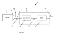
- FIG. 4 A further alternative embodiment of the invention is shown in Figure 4 in which like parts are denoted by like reference numerals.
- the engine system 2 is provided with a fuel injector 30 disposed in the exhaust passage 8 between the engine 4 and the 3-way catalytic converter 12.
- the compression-ignition internal combustion engine 4 is able to be operated at leaner operating points (less than stoichiometry) whilst the fuel injector 30 is used to alter the composition of the exhaust gases so as to ensure they are more balanced to optimize the operation of the 3-way catalytic converter 12.
- This has the effect of decreasing the generation of particulate emissions (because less particulates are generated at a leaner air/fuel ratio) whilst the 3-way catalytic converter 12 operates at high efficiency to reduce emissions of nitrogen oxide, carbon monoxide and hydrocarbons.
Landscapes
- Engineering & Computer Science (AREA)
- Chemical & Material Sciences (AREA)
- Combustion & Propulsion (AREA)
- Mechanical Engineering (AREA)
- General Engineering & Computer Science (AREA)
- Chemical Kinetics & Catalysis (AREA)
- Health & Medical Sciences (AREA)
- Toxicology (AREA)
- Materials Engineering (AREA)
- Exhaust Gas After Treatment (AREA)
- Electrical Control Of Air Or Fuel Supplied To Internal-Combustion Engine (AREA)
Priority Applications (5)
| Application Number | Priority Date | Filing Date | Title |
|---|---|---|---|
| EP07254103.0A EP2009265B1 (de) | 2007-06-05 | 2007-10-17 | Diesel-Brennkraftmachinensystem |
| JP2010510907A JP2010534781A (ja) | 2007-10-17 | 2008-07-24 | 内燃機関システム |
| PCT/IB2008/001935 WO2008149234A2 (en) | 2007-06-05 | 2008-07-24 | Internal combustion engine system |
| US12/599,543 US8381513B2 (en) | 2007-06-05 | 2008-07-24 | Internal combustion engine system |
| JP2012127705A JP5698706B2 (ja) | 2007-10-17 | 2012-06-05 | 内燃機関システム |
Applications Claiming Priority (3)
| Application Number | Priority Date | Filing Date | Title |
|---|---|---|---|
| EP07252263 | 2007-06-05 | ||
| EP07252264A EP2000653A1 (de) | 2007-06-05 | 2007-06-05 | Verfahren zum Betrieb einer Maschine mit Kompressionszündung |
| EP07254103.0A EP2009265B1 (de) | 2007-06-05 | 2007-10-17 | Diesel-Brennkraftmachinensystem |
Publications (2)
| Publication Number | Publication Date |
|---|---|
| EP2009265A1 true EP2009265A1 (de) | 2008-12-31 |
| EP2009265B1 EP2009265B1 (de) | 2018-10-03 |
Family
ID=39570817
Family Applications (1)
| Application Number | Title | Priority Date | Filing Date |
|---|---|---|---|
| EP07254103.0A Active EP2009265B1 (de) | 2007-06-05 | 2007-10-17 | Diesel-Brennkraftmachinensystem |
Country Status (3)
| Country | Link |
|---|---|
| US (1) | US8381513B2 (de) |
| EP (1) | EP2009265B1 (de) |
| WO (1) | WO2008149234A2 (de) |
Cited By (2)
| Publication number | Priority date | Publication date | Assignee | Title |
|---|---|---|---|---|
| WO2011077168A1 (en) * | 2009-12-24 | 2011-06-30 | Johnson Matthey Plc | Exhaust system for a vehicular positive ignition internal combustion engine |
| EP2592245A3 (de) * | 2011-11-08 | 2014-08-27 | International Engine Intellectual Property Company, LLC | Abgasreinigungssystem zur Reduktion von NOx-Emissionen |
Families Citing this family (5)
| Publication number | Priority date | Publication date | Assignee | Title |
|---|---|---|---|---|
| US8875494B2 (en) * | 2009-09-29 | 2014-11-04 | Ford Global Technologies, Llc | Fuel control for spark ignited engine having a particulate filter system |
| US20130019589A1 (en) * | 2011-07-19 | 2013-01-24 | GM Global Technology Operations LLC | Exhaust aftertreatment system for compression-ignition engines |
| DE102013009476A1 (de) * | 2013-06-06 | 2014-12-11 | GM Global Technology Operations LLC (n. d. Gesetzen des Staates Delaware) | Verfahren zur lastabhängigen Reduzierung des Kraftstoffverbrauchs nach einer Schubabschaltung |
| JP6412582B2 (ja) | 2014-02-12 | 2018-10-24 | アカーテース パワー,インク. | 低反応性圧縮着火対向ピストンエンジン |
| KR20210064481A (ko) * | 2019-11-25 | 2021-06-03 | 현대자동차주식회사 | 하이브리드 차량의 제어 장치 및 방법 |
Citations (7)
| Publication number | Priority date | Publication date | Assignee | Title |
|---|---|---|---|---|
| WO1995027128A1 (en) * | 1994-04-04 | 1995-10-12 | William Galen Ii Brown | Three-way catalytic oxidizer for diesel engines |
| EP0740056A2 (de) * | 1995-04-27 | 1996-10-30 | Toyota Jidosha Kabushiki Kaisha | Dieselbrennkraftmaschine mit Direkteinspritzung |
| EP1057983A1 (de) | 1999-06-04 | 2000-12-06 | Ford Global Technologies, Inc. | Abgasreinigungsvorrichtung für ein Fahrzeug mit niedriger Schadstoffemission |
| DE10208426A1 (de) * | 2001-02-28 | 2002-09-19 | Denso Corp | Gerät zum Steuern einer Dieselkraftmaschine |
| EP1350932A2 (de) | 2002-03-28 | 2003-10-08 | Nissan Motor Company, Limited | Abgaskontrollsystem für eine Diesel Brennkraftmaschine und Regelverfahren dafür |
| EP1544428A1 (de) * | 2002-08-26 | 2005-06-22 | Hitachi, Ltd. | VORRICHTUNG UND VERFAHREN ZUR KLûRUNG VON DIESELMOTORABGAS |
| EP1632668A2 (de) * | 2004-09-07 | 2006-03-08 | Institut Français du Pétrole | Vorrichtung zur Steuerung einer Brennkraftmaschine mit Direkteinspritzung und Brennkraftmaschine mit solcher Vorrichtung |
Family Cites Families (15)
| Publication number | Priority date | Publication date | Assignee | Title |
|---|---|---|---|---|
| JP3104674B2 (ja) | 1998-04-15 | 2000-10-30 | トヨタ自動車株式会社 | 圧縮着火式内燃機関 |
| JP2002081313A (ja) | 2000-06-29 | 2002-03-22 | Hino Motors Ltd | ディーゼルエンジンの排気浄化方法 |
| US6739295B1 (en) | 2000-08-17 | 2004-05-25 | Hitachi, Ltd. | Compression ignition internal combustion engine |
| JP3812362B2 (ja) * | 2001-04-19 | 2006-08-23 | 日産自動車株式会社 | 内燃機関の排気浄化装置 |
| JP3649188B2 (ja) * | 2002-01-16 | 2005-05-18 | トヨタ自動車株式会社 | 排気浄化装置付き内燃機関 |
| JP4114077B2 (ja) | 2003-04-25 | 2008-07-09 | 三菱自動車工業株式会社 | 内燃機関の排気浄化装置 |
| JP4285141B2 (ja) * | 2003-07-31 | 2009-06-24 | 日産自動車株式会社 | ディーゼルエンジンの燃料噴射制御装置 |
| JP4259361B2 (ja) | 2004-03-18 | 2009-04-30 | トヨタ自動車株式会社 | 内燃機関の排気浄化装置 |
| JP4407508B2 (ja) | 2004-12-21 | 2010-02-03 | 日産自動車株式会社 | 内燃機関のアイドル回転数制御装置 |
| JP2006274985A (ja) | 2005-03-30 | 2006-10-12 | Mitsubishi Fuso Truck & Bus Corp | 排気後処理装置 |
| DE102005059451A1 (de) * | 2005-12-13 | 2007-06-21 | Volkswagen Ag | Verfahren zur Reduzierung der NOx-Emission von Dieselmotoren |
| JP2007177641A (ja) | 2005-12-27 | 2007-07-12 | Nissan Motor Co Ltd | エンジンの制御装置 |
| JP2007198158A (ja) * | 2006-01-24 | 2007-08-09 | Mazda Motor Corp | 水素エンジンの空燃比制御装置 |
| DE102006038367A1 (de) * | 2006-08-16 | 2008-02-28 | Volkswagen Ag | Entschwefelung eines NOx-Speicherkatalysators |
| JP4163727B2 (ja) * | 2006-08-31 | 2008-10-08 | 本田技研工業株式会社 | 内燃機関のオイルレベル検出装置 |
-
2007
- 2007-10-17 EP EP07254103.0A patent/EP2009265B1/de active Active
-
2008
- 2008-07-24 WO PCT/IB2008/001935 patent/WO2008149234A2/en active Application Filing
- 2008-07-24 US US12/599,543 patent/US8381513B2/en active Active
Patent Citations (7)
| Publication number | Priority date | Publication date | Assignee | Title |
|---|---|---|---|---|
| WO1995027128A1 (en) * | 1994-04-04 | 1995-10-12 | William Galen Ii Brown | Three-way catalytic oxidizer for diesel engines |
| EP0740056A2 (de) * | 1995-04-27 | 1996-10-30 | Toyota Jidosha Kabushiki Kaisha | Dieselbrennkraftmaschine mit Direkteinspritzung |
| EP1057983A1 (de) | 1999-06-04 | 2000-12-06 | Ford Global Technologies, Inc. | Abgasreinigungsvorrichtung für ein Fahrzeug mit niedriger Schadstoffemission |
| DE10208426A1 (de) * | 2001-02-28 | 2002-09-19 | Denso Corp | Gerät zum Steuern einer Dieselkraftmaschine |
| EP1350932A2 (de) | 2002-03-28 | 2003-10-08 | Nissan Motor Company, Limited | Abgaskontrollsystem für eine Diesel Brennkraftmaschine und Regelverfahren dafür |
| EP1544428A1 (de) * | 2002-08-26 | 2005-06-22 | Hitachi, Ltd. | VORRICHTUNG UND VERFAHREN ZUR KLûRUNG VON DIESELMOTORABGAS |
| EP1632668A2 (de) * | 2004-09-07 | 2006-03-08 | Institut Français du Pétrole | Vorrichtung zur Steuerung einer Brennkraftmaschine mit Direkteinspritzung und Brennkraftmaschine mit solcher Vorrichtung |
Cited By (3)
| Publication number | Priority date | Publication date | Assignee | Title |
|---|---|---|---|---|
| WO2011077168A1 (en) * | 2009-12-24 | 2011-06-30 | Johnson Matthey Plc | Exhaust system for a vehicular positive ignition internal combustion engine |
| EP3372301A1 (de) * | 2009-12-24 | 2018-09-12 | Johnson Matthey Public Limited Company | Abgassystem für einen verbrennungsmotor eines fahrzeuges mit positiver zündung |
| EP2592245A3 (de) * | 2011-11-08 | 2014-08-27 | International Engine Intellectual Property Company, LLC | Abgasreinigungssystem zur Reduktion von NOx-Emissionen |
Also Published As
| Publication number | Publication date |
|---|---|
| WO2008149234A2 (en) | 2008-12-11 |
| US20100223909A1 (en) | 2010-09-09 |
| WO2008149234A3 (en) | 2009-04-02 |
| EP2009265B1 (de) | 2018-10-03 |
| US8381513B2 (en) | 2013-02-26 |
Similar Documents
| Publication | Publication Date | Title |
|---|---|---|
| US8464523B2 (en) | Targeted particulate matter filter regeneration system | |
| US8429899B2 (en) | Target particulate matter filter regeneration and temperature control system | |
| US9291079B2 (en) | Engine aftertreatment system with exhaust lambda control | |
| EP2646663B1 (de) | Magerverbrennungsmotor mit aktiver zündquelle und nachbehandlungssystem sowie verfahren | |
| US20100132334A1 (en) | Method and device for monitoring the regeneration of a pollution-removal system | |
| US20140041367A1 (en) | Operating Method for a Motor Vehicle Diesel Engine Having an Exhaust Emission Control System | |
| US8381513B2 (en) | Internal combustion engine system | |
| CA2441714A1 (en) | Hydrogen fueled spark ignition engine | |
| US9951673B2 (en) | Engine aftertreatment system with exhaust lambda control | |
| JP6569710B2 (ja) | エンジンの排気浄化装置 | |
| US9212585B2 (en) | Exhaust gas purifying apparatus for internal combustion engine | |
| CN104870784A (zh) | 天然气发动机以及天然气发动机的运转方法 | |
| EP3369898A1 (de) | Nachbehandlungssystem (ats) für einen ottomotor | |
| US20160061129A1 (en) | System and method of recovering oxidation catalyst performance | |
| US9429088B2 (en) | Lean NOx trap desulfation process | |
| US7617812B2 (en) | Method of operating a compression ignition engine | |
| US20190232225A1 (en) | Exhaust emission control device, method and computer program product for an engine | |
| WO2011101898A1 (ja) | 内燃機関の排気浄化装置 | |
| JP5698706B2 (ja) | 内燃機関システム | |
| US20200056521A1 (en) | Exhaust gas purification controller for engine | |
| US20200056526A1 (en) | Exhaust gas purification controller for engine | |
| EP3246548A1 (de) | Verfahren zur emissionsregelung in einem verbrennungsmotor | |
| US20200056527A1 (en) | Exhaust gas purification controller for engine |
Legal Events
| Date | Code | Title | Description |
|---|---|---|---|
| PUAI | Public reference made under article 153(3) epc to a published international application that has entered the european phase |
Free format text: ORIGINAL CODE: 0009012 |
|
| AK | Designated contracting states |
Kind code of ref document: A1 Designated state(s): AT BE BG CH CY CZ DE DK EE ES FI FR GB GR HU IE IS IT LI LT LU LV MC MT NL PL PT RO SE SI SK TR |
|
| AX | Request for extension of the european patent |
Extension state: AL BA HR MK RS |
|
| 17P | Request for examination filed |
Effective date: 20090609 |
|
| AKX | Designation fees paid |
Designated state(s): AT BE BG CH CY CZ DE DK EE ES FI FR GB GR HU IE IS IT LI LT LU LV MC MT NL PL PT RO SE SI SK TR |
|
| RAP1 | Party data changed (applicant data changed or rights of an application transferred) |
Owner name: DELPHI TECHNOLOGIES HOLDING S.A.R.L. |
|
| 17Q | First examination report despatched |
Effective date: 20100729 |
|
| RAP1 | Party data changed (applicant data changed or rights of an application transferred) |
Owner name: DELPHI INTERNATIONAL OPERATIONS LUXEMBOURG S.A.R.L |
|
| GRAP | Despatch of communication of intention to grant a patent |
Free format text: ORIGINAL CODE: EPIDOSNIGR1 |
|
| RIC1 | Information provided on ipc code assigned before grant |
Ipc: F02D 41/00 20060101AFI20180321BHEP Ipc: F01N 13/00 20100101ALI20180321BHEP Ipc: F02D 41/30 20060101ALI20180321BHEP Ipc: F01N 3/20 20060101ALI20180321BHEP Ipc: F01N 3/10 20060101ALI20180321BHEP Ipc: F01N 3/035 20060101ALI20180321BHEP |
|
| INTG | Intention to grant announced |
Effective date: 20180411 |
|
| GRAS | Grant fee paid |
Free format text: ORIGINAL CODE: EPIDOSNIGR3 |
|
| GRAA | (expected) grant |
Free format text: ORIGINAL CODE: 0009210 |
|
| AK | Designated contracting states |
Kind code of ref document: B1 Designated state(s): AT BE BG CH CY CZ DE DK EE ES FI FR GB GR HU IE IS IT LI LT LU LV MC MT NL PL PT RO SE SI SK TR |
|
| REG | Reference to a national code |
Ref country code: GB Ref legal event code: FG4D |
|
| REG | Reference to a national code |
Ref country code: CH Ref legal event code: EP Ref country code: AT Ref legal event code: REF Ref document number: 1048873 Country of ref document: AT Kind code of ref document: T Effective date: 20181015 |
|
| REG | Reference to a national code |
Ref country code: DE Ref legal event code: R096 Ref document number: 602007056341 Country of ref document: DE Ref country code: FR Ref legal event code: PLFP Year of fee payment: 12 |
|
| REG | Reference to a national code |
Ref country code: IE Ref legal event code: FG4D |
|
| REG | Reference to a national code |
Ref country code: NL Ref legal event code: MP Effective date: 20181003 |
|
| REG | Reference to a national code |
Ref country code: DE Ref legal event code: R081 Ref document number: 602007056341 Country of ref document: DE Owner name: DELPHI AUTOMOTIVE SYSTEMS LUXEMBOURG S.A., LU Free format text: FORMER OWNER: DELPHI INTERNATIONAL OPERATIONS LUXEMBOURG S.A R.L., BASCHARAGE, LU |
|
| REG | Reference to a national code |
Ref country code: LT Ref legal event code: MG4D |
|
| REG | Reference to a national code |
Ref country code: AT Ref legal event code: MK05 Ref document number: 1048873 Country of ref document: AT Kind code of ref document: T Effective date: 20181003 |
|
| REG | Reference to a national code |
Ref country code: GB Ref legal event code: 732E Free format text: REGISTERED BETWEEN 20190222 AND 20190227 |
|
| PG25 | Lapsed in a contracting state [announced via postgrant information from national office to epo] |
Ref country code: NL Free format text: LAPSE BECAUSE OF FAILURE TO SUBMIT A TRANSLATION OF THE DESCRIPTION OR TO PAY THE FEE WITHIN THE PRESCRIBED TIME-LIMIT Effective date: 20181003 |
|
| PG25 | Lapsed in a contracting state [announced via postgrant information from national office to epo] |
Ref country code: ES Free format text: LAPSE BECAUSE OF FAILURE TO SUBMIT A TRANSLATION OF THE DESCRIPTION OR TO PAY THE FEE WITHIN THE PRESCRIBED TIME-LIMIT Effective date: 20181003 Ref country code: LV Free format text: LAPSE BECAUSE OF FAILURE TO SUBMIT A TRANSLATION OF THE DESCRIPTION OR TO PAY THE FEE WITHIN THE PRESCRIBED TIME-LIMIT Effective date: 20181003 Ref country code: FI Free format text: LAPSE BECAUSE OF FAILURE TO SUBMIT A TRANSLATION OF THE DESCRIPTION OR TO PAY THE FEE WITHIN THE PRESCRIBED TIME-LIMIT Effective date: 20181003 Ref country code: BG Free format text: LAPSE BECAUSE OF FAILURE TO SUBMIT A TRANSLATION OF THE DESCRIPTION OR TO PAY THE FEE WITHIN THE PRESCRIBED TIME-LIMIT Effective date: 20190103 Ref country code: PL Free format text: LAPSE BECAUSE OF FAILURE TO SUBMIT A TRANSLATION OF THE DESCRIPTION OR TO PAY THE FEE WITHIN THE PRESCRIBED TIME-LIMIT Effective date: 20181003 Ref country code: AT Free format text: LAPSE BECAUSE OF FAILURE TO SUBMIT A TRANSLATION OF THE DESCRIPTION OR TO PAY THE FEE WITHIN THE PRESCRIBED TIME-LIMIT Effective date: 20181003 Ref country code: LT Free format text: LAPSE BECAUSE OF FAILURE TO SUBMIT A TRANSLATION OF THE DESCRIPTION OR TO PAY THE FEE WITHIN THE PRESCRIBED TIME-LIMIT Effective date: 20181003 Ref country code: IS Free format text: LAPSE BECAUSE OF FAILURE TO SUBMIT A TRANSLATION OF THE DESCRIPTION OR TO PAY THE FEE WITHIN THE PRESCRIBED TIME-LIMIT Effective date: 20190203 Ref country code: CZ Free format text: LAPSE BECAUSE OF FAILURE TO SUBMIT A TRANSLATION OF THE DESCRIPTION OR TO PAY THE FEE WITHIN THE PRESCRIBED TIME-LIMIT Effective date: 20181003 |
|
| PG25 | Lapsed in a contracting state [announced via postgrant information from national office to epo] |
Ref country code: SE Free format text: LAPSE BECAUSE OF FAILURE TO SUBMIT A TRANSLATION OF THE DESCRIPTION OR TO PAY THE FEE WITHIN THE PRESCRIBED TIME-LIMIT Effective date: 20181003 Ref country code: GR Free format text: LAPSE BECAUSE OF FAILURE TO SUBMIT A TRANSLATION OF THE DESCRIPTION OR TO PAY THE FEE WITHIN THE PRESCRIBED TIME-LIMIT Effective date: 20190104 Ref country code: PT Free format text: LAPSE BECAUSE OF FAILURE TO SUBMIT A TRANSLATION OF THE DESCRIPTION OR TO PAY THE FEE WITHIN THE PRESCRIBED TIME-LIMIT Effective date: 20190203 |
|
| REG | Reference to a national code |
Ref country code: CH Ref legal event code: PL |
|
| REG | Reference to a national code |
Ref country code: BE Ref legal event code: MM Effective date: 20181031 |
|
| PG25 | Lapsed in a contracting state [announced via postgrant information from national office to epo] |
Ref country code: LU Free format text: LAPSE BECAUSE OF NON-PAYMENT OF DUE FEES Effective date: 20181017 |
|
| REG | Reference to a national code |
Ref country code: DE Ref legal event code: R097 Ref document number: 602007056341 Country of ref document: DE |
|
| REG | Reference to a national code |
Ref country code: IE Ref legal event code: MM4A |
|
| PG25 | Lapsed in a contracting state [announced via postgrant information from national office to epo] |
Ref country code: IT Free format text: LAPSE BECAUSE OF FAILURE TO SUBMIT A TRANSLATION OF THE DESCRIPTION OR TO PAY THE FEE WITHIN THE PRESCRIBED TIME-LIMIT Effective date: 20181003 Ref country code: DK Free format text: LAPSE BECAUSE OF FAILURE TO SUBMIT A TRANSLATION OF THE DESCRIPTION OR TO PAY THE FEE WITHIN THE PRESCRIBED TIME-LIMIT Effective date: 20181003 |
|
| PLBE | No opposition filed within time limit |
Free format text: ORIGINAL CODE: 0009261 |
|
| STAA | Information on the status of an ep patent application or granted ep patent |
Free format text: STATUS: NO OPPOSITION FILED WITHIN TIME LIMIT |
|
| PG25 | Lapsed in a contracting state [announced via postgrant information from national office to epo] |
Ref country code: RO Free format text: LAPSE BECAUSE OF FAILURE TO SUBMIT A TRANSLATION OF THE DESCRIPTION OR TO PAY THE FEE WITHIN THE PRESCRIBED TIME-LIMIT Effective date: 20181003 Ref country code: SK Free format text: LAPSE BECAUSE OF FAILURE TO SUBMIT A TRANSLATION OF THE DESCRIPTION OR TO PAY THE FEE WITHIN THE PRESCRIBED TIME-LIMIT Effective date: 20181003 Ref country code: EE Free format text: LAPSE BECAUSE OF FAILURE TO SUBMIT A TRANSLATION OF THE DESCRIPTION OR TO PAY THE FEE WITHIN THE PRESCRIBED TIME-LIMIT Effective date: 20181003 Ref country code: LI Free format text: LAPSE BECAUSE OF NON-PAYMENT OF DUE FEES Effective date: 20181031 Ref country code: CH Free format text: LAPSE BECAUSE OF NON-PAYMENT OF DUE FEES Effective date: 20181031 Ref country code: MC Free format text: LAPSE BECAUSE OF FAILURE TO SUBMIT A TRANSLATION OF THE DESCRIPTION OR TO PAY THE FEE WITHIN THE PRESCRIBED TIME-LIMIT Effective date: 20181003 Ref country code: BE Free format text: LAPSE BECAUSE OF NON-PAYMENT OF DUE FEES Effective date: 20181031 |
|
| 26N | No opposition filed |
Effective date: 20190704 |
|
| PG25 | Lapsed in a contracting state [announced via postgrant information from national office to epo] |
Ref country code: IE Free format text: LAPSE BECAUSE OF NON-PAYMENT OF DUE FEES Effective date: 20181017 Ref country code: SI Free format text: LAPSE BECAUSE OF FAILURE TO SUBMIT A TRANSLATION OF THE DESCRIPTION OR TO PAY THE FEE WITHIN THE PRESCRIBED TIME-LIMIT Effective date: 20181003 |
|
| PG25 | Lapsed in a contracting state [announced via postgrant information from national office to epo] |
Ref country code: MT Free format text: LAPSE BECAUSE OF NON-PAYMENT OF DUE FEES Effective date: 20181017 |
|
| PG25 | Lapsed in a contracting state [announced via postgrant information from national office to epo] |
Ref country code: TR Free format text: LAPSE BECAUSE OF FAILURE TO SUBMIT A TRANSLATION OF THE DESCRIPTION OR TO PAY THE FEE WITHIN THE PRESCRIBED TIME-LIMIT Effective date: 20181003 |
|
| PG25 | Lapsed in a contracting state [announced via postgrant information from national office to epo] |
Ref country code: HU Free format text: LAPSE BECAUSE OF FAILURE TO SUBMIT A TRANSLATION OF THE DESCRIPTION OR TO PAY THE FEE WITHIN THE PRESCRIBED TIME-LIMIT; INVALID AB INITIO Effective date: 20071017 Ref country code: CY Free format text: LAPSE BECAUSE OF FAILURE TO SUBMIT A TRANSLATION OF THE DESCRIPTION OR TO PAY THE FEE WITHIN THE PRESCRIBED TIME-LIMIT Effective date: 20181003 |
|
| PGFP | Annual fee paid to national office [announced via postgrant information from national office to epo] |
Ref country code: FR Payment date: 20201026 Year of fee payment: 14 Ref country code: GB Payment date: 20201027 Year of fee payment: 14 |
|
| GBPC | Gb: european patent ceased through non-payment of renewal fee |
Effective date: 20211017 |
|
| PG25 | Lapsed in a contracting state [announced via postgrant information from national office to epo] |
Ref country code: GB Free format text: LAPSE BECAUSE OF NON-PAYMENT OF DUE FEES Effective date: 20211017 |
|
| PG25 | Lapsed in a contracting state [announced via postgrant information from national office to epo] |
Ref country code: FR Free format text: LAPSE BECAUSE OF NON-PAYMENT OF DUE FEES Effective date: 20211031 |
|
| P01 | Opt-out of the competence of the unified patent court (upc) registered |
Effective date: 20230327 |
|
| PGFP | Annual fee paid to national office [announced via postgrant information from national office to epo] |
Ref country code: DE Payment date: 20230915 Year of fee payment: 17 |