EP2009253A1 - Method of decomposing gas hydrate, and apparatus therefor, in gas turbine combined power generation system - Google Patents
Method of decomposing gas hydrate, and apparatus therefor, in gas turbine combined power generation system Download PDFInfo
- Publication number
- EP2009253A1 EP2009253A1 EP06731913A EP06731913A EP2009253A1 EP 2009253 A1 EP2009253 A1 EP 2009253A1 EP 06731913 A EP06731913 A EP 06731913A EP 06731913 A EP06731913 A EP 06731913A EP 2009253 A1 EP2009253 A1 EP 2009253A1
- Authority
- EP
- European Patent Office
- Prior art keywords
- gas
- gas hydrate
- condenser
- condensate
- power generation
- Prior art date
- Legal status (The legal status is an assumption and is not a legal conclusion. Google has not performed a legal analysis and makes no representation as to the accuracy of the status listed.)
- Withdrawn
Links
- NMJORVOYSJLJGU-UHFFFAOYSA-N methane clathrate Chemical compound C.C.C.C.O.O.O.O.O.O.O.O.O.O.O.O.O.O.O.O.O.O.O.O.O.O.O NMJORVOYSJLJGU-UHFFFAOYSA-N 0.000 title claims abstract description 80
- 238000010248 power generation Methods 0.000 title claims abstract description 23
- 238000000034 method Methods 0.000 title claims description 8
- XLYOFNOQVPJJNP-UHFFFAOYSA-N water Substances O XLYOFNOQVPJJNP-UHFFFAOYSA-N 0.000 claims abstract description 52
- 238000000354 decomposition reaction Methods 0.000 claims abstract description 13
- 239000000446 fuel Substances 0.000 claims abstract description 8
- 238000005979 thermal decomposition reaction Methods 0.000 claims description 20
- 239000007789 gas Substances 0.000 description 27
- 238000002309 gasification Methods 0.000 description 22
- VNWKTOKETHGBQD-UHFFFAOYSA-N methane Chemical compound C VNWKTOKETHGBQD-UHFFFAOYSA-N 0.000 description 18
- 239000013535 sea water Substances 0.000 description 16
- 239000003345 natural gas Substances 0.000 description 9
- 238000010438 heat treatment Methods 0.000 description 8
- 239000007788 liquid Substances 0.000 description 8
- 239000002918 waste heat Substances 0.000 description 8
- 238000001816 cooling Methods 0.000 description 7
- 239000007921 spray Substances 0.000 description 6
- 238000009833 condensation Methods 0.000 description 5
- 230000005494 condensation Effects 0.000 description 5
- 238000002485 combustion reaction Methods 0.000 description 4
- 239000000498 cooling water Substances 0.000 description 4
- 238000010586 diagram Methods 0.000 description 4
- 239000003949 liquefied natural gas Substances 0.000 description 4
- 239000000463 material Substances 0.000 description 4
- 239000002002 slurry Substances 0.000 description 4
- 230000003247 decreasing effect Effects 0.000 description 2
- 239000002737 fuel gas Substances 0.000 description 2
- 239000008188 pellet Substances 0.000 description 2
- 230000035484 reaction time Effects 0.000 description 2
- 238000011084 recovery Methods 0.000 description 2
- 239000008400 supply water Substances 0.000 description 2
- 239000012530 fluid Substances 0.000 description 1
- 239000008239 natural water Substances 0.000 description 1
- 230000001737 promoting effect Effects 0.000 description 1
- 229920006395 saturated elastomer Polymers 0.000 description 1
Images


Classifications
-
- F—MECHANICAL ENGINEERING; LIGHTING; HEATING; WEAPONS; BLASTING
- F01—MACHINES OR ENGINES IN GENERAL; ENGINE PLANTS IN GENERAL; STEAM ENGINES
- F01K—STEAM ENGINE PLANTS; STEAM ACCUMULATORS; ENGINE PLANTS NOT OTHERWISE PROVIDED FOR; ENGINES USING SPECIAL WORKING FLUIDS OR CYCLES
- F01K23/00—Plants characterised by more than one engine delivering power external to the plant, the engines being driven by different fluids
- F01K23/02—Plants characterised by more than one engine delivering power external to the plant, the engines being driven by different fluids the engine cycles being thermally coupled
- F01K23/06—Plants characterised by more than one engine delivering power external to the plant, the engines being driven by different fluids the engine cycles being thermally coupled combustion heat from one cycle heating the fluid in another cycle
- F01K23/10—Plants characterised by more than one engine delivering power external to the plant, the engines being driven by different fluids the engine cycles being thermally coupled combustion heat from one cycle heating the fluid in another cycle with exhaust fluid of one cycle heating the fluid in another cycle
-
- F—MECHANICAL ENGINEERING; LIGHTING; HEATING; WEAPONS; BLASTING
- F01—MACHINES OR ENGINES IN GENERAL; ENGINE PLANTS IN GENERAL; STEAM ENGINES
- F01K—STEAM ENGINE PLANTS; STEAM ACCUMULATORS; ENGINE PLANTS NOT OTHERWISE PROVIDED FOR; ENGINES USING SPECIAL WORKING FLUIDS OR CYCLES
- F01K9/00—Plants characterised by condensers arranged or modified to co-operate with the engines
- F01K9/003—Plants characterised by condensers arranged or modified to co-operate with the engines condenser cooling circuits
-
- F—MECHANICAL ENGINEERING; LIGHTING; HEATING; WEAPONS; BLASTING
- F02—COMBUSTION ENGINES; HOT-GAS OR COMBUSTION-PRODUCT ENGINE PLANTS
- F02C—GAS-TURBINE PLANTS; AIR INTAKES FOR JET-PROPULSION PLANTS; CONTROLLING FUEL SUPPLY IN AIR-BREATHING JET-PROPULSION PLANTS
- F02C3/00—Gas-turbine plants characterised by the use of combustion products as the working fluid
- F02C3/20—Gas-turbine plants characterised by the use of combustion products as the working fluid using a special fuel, oxidant, or dilution fluid to generate the combustion products
- F02C3/26—Gas-turbine plants characterised by the use of combustion products as the working fluid using a special fuel, oxidant, or dilution fluid to generate the combustion products the fuel or oxidant being solid or pulverulent, e.g. in slurry or suspension
- F02C3/28—Gas-turbine plants characterised by the use of combustion products as the working fluid using a special fuel, oxidant, or dilution fluid to generate the combustion products the fuel or oxidant being solid or pulverulent, e.g. in slurry or suspension using a separate gas producer for gasifying the fuel before combustion
-
- F—MECHANICAL ENGINEERING; LIGHTING; HEATING; WEAPONS; BLASTING
- F28—HEAT EXCHANGE IN GENERAL
- F28B—STEAM OR VAPOUR CONDENSERS
- F28B5/00—Condensers employing a combination of the methods covered by main groups F28B1/00 and F28B3/00; Other condensers
-
- F—MECHANICAL ENGINEERING; LIGHTING; HEATING; WEAPONS; BLASTING
- F28—HEAT EXCHANGE IN GENERAL
- F28D—HEAT-EXCHANGE APPARATUS, NOT PROVIDED FOR IN ANOTHER SUBCLASS, IN WHICH THE HEAT-EXCHANGE MEDIA DO NOT COME INTO DIRECT CONTACT
- F28D7/00—Heat-exchange apparatus having stationary tubular conduit assemblies for both heat-exchange media, the media being in contact with different sides of a conduit wall
- F28D7/16—Heat-exchange apparatus having stationary tubular conduit assemblies for both heat-exchange media, the media being in contact with different sides of a conduit wall the conduits being arranged in parallel spaced relation
-
- Y—GENERAL TAGGING OF NEW TECHNOLOGICAL DEVELOPMENTS; GENERAL TAGGING OF CROSS-SECTIONAL TECHNOLOGIES SPANNING OVER SEVERAL SECTIONS OF THE IPC; TECHNICAL SUBJECTS COVERED BY FORMER USPC CROSS-REFERENCE ART COLLECTIONS [XRACs] AND DIGESTS
- Y02—TECHNOLOGIES OR APPLICATIONS FOR MITIGATION OR ADAPTATION AGAINST CLIMATE CHANGE
- Y02E—REDUCTION OF GREENHOUSE GAS [GHG] EMISSIONS, RELATED TO ENERGY GENERATION, TRANSMISSION OR DISTRIBUTION
- Y02E20/00—Combustion technologies with mitigation potential
- Y02E20/16—Combined cycle power plant [CCPP], or combined cycle gas turbine [CCGT]
Definitions
- the present invention relates to a method of thermally decomposing gas hydrate, and an apparatus therefor, in a gas turbine combined power generation system.
- NGH natural gas hydrate
- LNG liquid natural gas
- NGH When regasifying NGH into natural gas, it has been proposed that NGH, being offloaded from an NGH carrier vessel and into an NGH facility, be fed into a gasification tank and then regasified using seawater. Seawater is also used as a heat source when gasifying LNG.
- NGH is a hydrate of natural gas and water, and the temperature difference between the temperature of NGH (-20 °C, for example) and the temperature of seawater (21 °C, for example) is small.
- NGH gasification is difficult compared to that of LNG.
- the heat transfer area during gasification must be inevitably made larger.
- the temperature (33 °C, for example) of the condenser in gas turbine combined power generation equipment is higher than the temperature of the seawater (typically, the seawater temperature is set to 21 °C). For this reason, by using steam condensate instead of seawater, a heat exchanger for gasification can be rendered unnecessary.
- the present invention was devised to resolve such problems, an object thereof being to provide a method and apparatus for thermally decomposing gas hydrate in a gas turbine combined power generation system, wherein a heat exchanger for gasification is rendered unnecessary, and wherein the condensate temperature does not fluctuate.
- the invention disclosed in claim 1 is a method of decomposing gas hydrate in a gas turbine combined power generation system, the gas turbine combined power generation system using, as a fuel, gas generated by decomposition of gas hydrate.
- the method includes the steps of: circulating condensate generated in a condenser to the vapor inlet side of the condenser; exchanging heat between the circulating condensate and circulating water supplied to decompose gas hydrate; and using the heat-exchanged circulating water to decompose gas hydrate.
- the invention disclosed in claim 2 is an apparatus for decomposing gas hydrate in a gas turbine combined power generation system, the gas turbine combined power generation system using, as a fuel, gas generated by decomposition of gas hydrate.
- the apparatus is provided with: a pump that circulates condensate generated in a condenser to the vapor inlet side of the condenser; a heat exchanger that causes heat to be exchanged between the circulating condensate and circulating water supplied to decompose gas hydrate; and a pump that circulates the circulating water to a gas hydrate thermal decomposition tank.
- the invention disclosed in claim 1 is utilized in a gas turbine combined power generation system using, as a fuel, gas generated by decomposition of gas hydrate.
- Condensate generated in a condenser is circulated to the vapor inlet side of the condenser, the circulating condensate is then made to exchange heat with circulating water supplied to decompose gas hydrate, and then the heat-exchanged circulating water is used to decompose gas hydrate. Consequently, the following advantages are obtained.
- the invention disclosed in claim 2 is utilized in a gas turbine combined power generation system using, as a fuel, gas generated by decomposition of gas hydrate, and is provided with: a pump that circulates condensate generated in a condenser to the vapor inlet side of the condenser; a heat exchanger that causes heat to be exchanged between the circulating condensate and circulating water supplied to decompose gas hydrate; and a pump that circulates the circulating water to a gas hydrate thermal decomposition tank.
- a pump that circulates condensate generated in a condenser to the vapor inlet side of the condenser
- a heat exchanger that causes heat to be exchanged between the circulating condensate and circulating water supplied to decompose gas hydrate
- a pump that circulates the circulating water to a gas hydrate thermal decomposition tank.
- the gas hydrate thermal decomposition reaction time is determined according to the temperature difference ( ⁇ T) between the equilibrium temperature of the gas hydrate in the gasification tank and the operating temperature in the tank. Since the present invention is able to increase ⁇ T, the gas hydrate thermal decomposition time can be shortened.
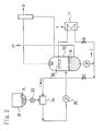
- FIG. 1 (A) represents gas turbine power generation equipment, and (B) represents a gas hydrate thermal decomposition apparatus.
- the gas turbine power generation equipment (A) includes a compressor 1 and a turbine 2 coaxially coupled about a turbine shaft 3, and burns fuel gas (more specifically, natural gas (b)) inside a combustion chamber 4 using air (a) compressed at the compressor 1. At that point, the high-temperature, high-pressure fuel gas (c) thus generated is expanded in the turbine 2 so as to drive a power generator 5 coupled to the turbine shaft 3.
- the gas turbine power generation equipment (A) feeds high-temperature exhaust gas (d) exhausted from the turbine 2 to a waste heat boiler 6, and steam (e) generated by heat recovery is then respectively expanded in steam turbines 7, 8, and 9 coupled to the turbine shaft 3, thereby driving the power generator 5.
- Steam (f) exhausted from the steam turbines 7, 8, and 9 is condensed at a condenser 10, the condensate being again returned to the waste heat boiler 6.
- the gas hydrate thermal decomposition apparatus (B) thermally decomposes gas hydrate (h) in pellet form in a gasification tank 32, the gas hydrate (h) having been transported to a storage tank 31 by a carrier vessel 30.
- the natural gas (b) generated by thermal decomposition is supplied to the above combustion chamber 4, while the dissociated liquid (m) generated at the same time is used as cooling water for intake cooling of the compressor 1, as boiler supply water for the waste heat boiler 6, and as ballast water for the carrier vessel 30.
- the gas hydrate (h) in the storage tank 31 is first finely crushed by a crusher (not shown in the drawings), and subsequently supplied to a mixer 34 by a rotary valve 33.
- the gas hydrate (h) (approx. 10 mm) inside the mixer 34 is slurried by circulating water (i) supplied from the gasification tank 32, and then fed into the gasification tank 32 by a slurry pump 35.
- the circulating water (i) from the gasification tank 32 is heated at a heat exchanger 11 using condensate (n) from the condenser 10 as a heat source, whereby the circulating water (i) is provided with the necessary decomposition heat for decomposing the gas hydrate (h).
- the gas hydrate (h) in the gasification tank 32 is sprayed with the heated circulating water (i) from spray nozzles 36 provided inside the tank.
- the gas hydrate (h) dissociates by thermal decomposition into natural gas (b) and a portion of the circulating water (i) (i.e., dissociated liquid).
- the natural gas (b) dissociated is fed into the gas turbine combustion chamber 4. Since the generated portion of the circulating water (i) (i.e., the dissociated liquid (m)) collects in the gasification tank 32, the dissociated liquid (m) is continually flushed.
- this portion of the circulating water (i) is used as cooling water for intake cooling of the gas turbine 2, as boiler supply water for the waste heat boiler 6, and as ballast water for the carrier vessel 30.
- all water except the boiler feed water for the waste heat boiler 6 is accumulated in a water tank 12, and subsequently added to the ballast water of the carrier vessel 30 by a recovered water transfer pump 13.
- the condensate (n) of the condenser 10 has a temperature exceeding that of seawater (33 °C, for example), and is an ideal heat source for regasification of the gas hydrate (h).
- the temperature of the seawater (p) is 21 °C.
- the condensate temperature falls below a predefined temperature (33 °C, for example) and essentially becomes boiler feed water, leading to a state of reduced power generation efficiency. Consequently, it is necessary to plan such that the temperature of the condensate does not fluctuate.
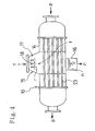
- a portion of the body 14 of a horizontal condenser 10 is increased in diameter, a condensate collector 16 is provided underneath this large-diameter portion 15, and in addition, condensate spray nozzles 18 are provided in the upper space (inlet) 17 of the large-diameter portion 15.
- the invention is configured such that, after drawing a portion of the condensate (n) in the condensate collector 16 by using a first pump 19, circulating water (r) is injected into the steam (f) in the upper space (inlet) 17 of the condenser 10, the circulating water (r) being sprayed from the above condensate spray nozzles 18.
- the circulating water (r) is generated from the condensate (n) via the heat exchanger 11 already described.
- the heat transfer area of the heat transfer tubes 23 can be made smaller than that of a conventional condenser (i.e., a condenser using only seawater for heating/cooling).
- the majority of the circulating water (r) is pumped out by a second pump 20, flows into a condensation chamber 21, and is subsequently fed into the waste heat boiler 6 by a condensate recovery pump 22.
- 25 is a recovered water pump
- 26 is a decomposition tank fluid recirculation pump
- 27 is a cooling water pump.
- Fig. 5 illustrates the heat and material balance in a gasification tank that feeds 50 t/h natural gas into a gas turbine combustion chamber.
- Gas hydrate (h) in pellet form in a storage tank 31 is first finely crushed by a crusher (not shown in the drawings), and subsequently fed into a mixer 34 by a rotary valve 33 (feed rate: 375 t/h, temperature: -20 °C).
- Gas hydrate (h) (approx. 10 mm) in the mixer 34 is slurried (slurry concentration: 0.2 %) by water (i) (circulating water) (water temperature: 10 °C, pressure: 3 ata (0.29 MPa), feed rate: 1,499 t/h) supplied from a gasification tank 32.
- the slurry is then fed into the gasification tank 32 by a slurry pump 35.
- the gasification tank 32 has an operating temperature of 10 °C and an operating pressure of 35 ata (3.43 MPa), wherein water (i) (circulating water) at the operating temperature is circulated (4,565 t/h), the water (i) being heated in an external heat exchanger 11, using circulating water (r) as a heat source.
- the heated water (i) (circulating water) (20 °C) is then sprayed into the tank from spray nozzles 36.
- the amount of the dissociated water (m) is 325 t/h.
- the amount of natural gas is 50 t/h plus some amount (0.0179 t/h) in the form of moisture-saturated gas, these amounts corresponding to the quantity of gas hydrate that was loaded into the tank.
- Fig. 6 illustrates the heat and material balance in an improved steam turbine condenser.
- the condenser 10 drain rate: 388 t/h, entropy: 33.0 kcal/kg
- seawater for cooling
- feed rate 23,298 t/h
- the condenser is modified to recirculate (circulation rate: 5,706 t/h) and spray drain.
- the gas hydrate decomposition heat corresponds to 21.4 % of the heat load of the condenser.
Landscapes
- Engineering & Computer Science (AREA)
- Mechanical Engineering (AREA)
- General Engineering & Computer Science (AREA)
- Chemical & Material Sciences (AREA)
- Combustion & Propulsion (AREA)
- Physics & Mathematics (AREA)
- Thermal Sciences (AREA)
- Engine Equipment That Uses Special Cycles (AREA)
Abstract
Description
- The present invention relates to a method of thermally decomposing gas hydrate, and an apparatus therefor, in a gas turbine combined power generation system.
- Recently, proposals are being considered wherein NGH (natural gas hydrate) is produced instead of LNG (liquid natural gas) in overseas gas fields, and after importing such NGH, the NGH is regasified and restored to natural gas at an NGH facility, being then supplied fuel to gas turbine combined power generation equipment (see patent literature 1 and patent literature 2, for example).
- Patent Literature 1: Japanese patent application Kokai publication No.
2002-371862 Fig. 1 ) - Patent Literature 2: Japanese patent application Kokai publication No.
11-200884 Fig. 1 ) - When regasifying NGH into natural gas, it has been proposed that NGH, being offloaded from an NGH carrier vessel and into an NGH facility, be fed into a gasification tank and then regasified using seawater. Seawater is also used as a heat source when gasifying LNG. However, NGH is a hydrate of natural gas and water, and the temperature difference between the temperature of NGH (-20 °C, for example) and the temperature of seawater (21 °C, for example) is small. For these and other reasons, NGH gasification is difficult compared to that of LNG. Thus, the heat transfer area during gasification must be inevitably made larger.
- Meanwhile, in gas turbine combined power generation equipment, steam exhausted from a steam turbine is condensed by a condenser, and subsequently returned to a waste heat boiler, where the condensed steam is re-heated using gas turbine exhaust gas.
- Typically, the temperature (33 °C, for example) of the condenser in gas turbine combined power generation equipment is higher than the temperature of the seawater (typically, the seawater temperature is set to 21 °C). For this reason, by using steam condensate instead of seawater, a heat exchanger for gasification can be rendered unnecessary.
- However, if the steam condensate used for regasifying NGH exceeds a predefined value of the gas turbine power generation equipment, the temperature of the condensate will fall below a predefined temperature (33 °C, for example). As a result, the quantity and temperature of the steam generated in the waste heat boiler will decrease, leading to a state of reduced power generation efficiency.
- The present invention was devised to resolve such problems, an object thereof being to provide a method and apparatus for thermally decomposing gas hydrate in a gas turbine combined power generation system, wherein a heat exchanger for gasification is rendered unnecessary, and wherein the condensate temperature does not fluctuate.
- In order to achieve such an object, the present invention is configured as follows. The invention disclosed in claim 1 is a method of decomposing gas hydrate in a gas turbine combined power generation system, the gas turbine combined power generation system using, as a fuel, gas generated by decomposition of gas hydrate. The method includes the steps of: circulating condensate generated in a condenser to the vapor inlet side of the condenser; exchanging heat between the circulating condensate and circulating water supplied to decompose gas hydrate; and using the heat-exchanged circulating water to decompose gas hydrate.
- The invention disclosed in claim 2 is an apparatus for decomposing gas hydrate in a gas turbine combined power generation system, the gas turbine combined power generation system using, as a fuel, gas generated by decomposition of gas hydrate. The apparatus is provided with: a pump that circulates condensate generated in a condenser to the vapor inlet side of the condenser; a heat exchanger that causes heat to be exchanged between the circulating condensate and circulating water supplied to decompose gas hydrate; and a pump that circulates the circulating water to a gas hydrate thermal decomposition tank.
- As described above, the invention disclosed in claim 1 is utilized in a gas turbine combined power generation system using, as a fuel, gas generated by decomposition of gas hydrate. Condensate generated in a condenser is circulated to the vapor inlet side of the condenser, the circulating condensate is then made to exchange heat with circulating water supplied to decompose gas hydrate, and then the heat-exchanged circulating water is used to decompose gas hydrate. Consequently, the following advantages are obtained.
-
- (a) Since the heating medium (i.e., the circulating water) for thermal decomposition of gas hydrate is heated by using condensate from the condenser, the operating temperature of the gasification tank can be set to a high value.
-
- (b) The gas hydrate thermal decomposition reaction time is determined according to the temperature difference (ΔT) between the equilibrium temperature of the gas hydrate in the gasification tank and the operating temperature in the tank. Since the present invention is able to increase ΔT, the gas hydrate thermal decomposition time can be shortened.
-
- (c) Since the gas hydrate residence time is short when the gas hydrate thermal decomposition time is short, the volume of the gasification tank can be made smaller.
-
- (d) If circulating water is directly sprayed onto the heat transfer tubes of the condenser, the film thickness of the liquid film on the circumference of the heat transfer tubes becomes larger and is thought to inhibit heat transfer. However, if exhaust steam from the steam turbine and circulating condensate are put into direct contact at the condenser inlet as described above, condensation of the exhaust steam from the steam turbine is facilitated and seawater quantities are reduced. For these reasons, the heat transfer area of the condenser can be made smaller than that of a conventional condenser (i.e., a condenser using only seawater for heating/cooling).
-
- (e) Since the temperature difference between the heating medium for gas hydrate thermal decomposition (i.e., the circulating water) and the circulating condensate is increased compared to that of seawater, the heat transfer area of the heat exchanger for gas hydrate thermal decomposition can be decreased.
- Meanwhile, the invention disclosed in claim 2 is utilized in a gas turbine combined power generation system using, as a fuel, gas generated by decomposition of gas hydrate, and is provided with: a pump that circulates condensate generated in a condenser to the vapor inlet side of the condenser; a heat exchanger that causes heat to be exchanged between the circulating condensate and circulating water supplied to decompose gas hydrate; and a pump that circulates the circulating water to a gas hydrate thermal decomposition tank. Thus, similarly to the invention disclosed in claim 1, the following advantages are obtained.
-
- (a) Since the heating medium (i.e., the dissociated liquid) for thermal decomposition of gas hydrate is heated by using condensate from the condenser, the operating temperature of the gasification tank can be set to a high value.
- (b) The gas hydrate thermal decomposition reaction time is determined according to the temperature difference (ΔT) between the equilibrium temperature of the gas hydrate in the gasification tank and the operating temperature in the tank. Since the present invention is able to increase ΔT, the gas hydrate thermal decomposition time can be shortened.
-
- (c) Since the gas hydrate residence time is short when the gas hydrate thermal decomposition time is short, the volume of the gasification tank can be made smaller.
-
- (d) If circulating water is directly sprayed onto the heat transfer tubes of the condenser, the film thickness of the liquid film on the circumference of the heat transfer tubes becomes larger and is thought to inhibit heat transfer. However, if exhaust steam from the steam turbine and circulating condensate are put into direct contact at the condenser inlet as described above, condensation of the exhaust steam from the steam turbine is facilitated and seawater quantities are reduced. For these reasons, the heat transfer area of the condenser can be made smaller than that of a conventional condenser (i.e., a condenser using only seawater for heating/cooling)
-
- (e) Since the temperature difference between the heating medium for gas hydrate thermal decomposition (i.e., the circulating water) and the circulating condensate can be increased, the heat transfer area of the heat exchanger for gas hydrate thermal decomposition can be decreased.
-
-
Fig. 1 is a schematic diagram of the configuration of equipment for carrying out the method of thermally decomposing gas hydrate in a co-generation system in accordance with the present invention. -
Fig. 2 is a schematic diagram of the configuration of a gas hydrate thermal decomposition apparatus. -
Fig. 3 is a horizontal cross-sectional view of an improved steam turbine condenser. -
Fig. 4 is a vertical cross-sectional view of an improved steam turbine condenser. -
Fig. 5 is a diagram illustrating the heat and material balance in a gasification tank. -
Fig. 6 is a diagram illustrating the heat and material balance in an improved steam turbine condenser. - Hereinafter, embodiments of the invention will be described with reference to the accompanying drawings. In
Fig. 1 , (A) represents gas turbine power generation equipment, and (B) represents a gas hydrate thermal decomposition apparatus. - The gas turbine power generation equipment (A) includes a compressor 1 and a turbine 2 coaxially coupled about a turbine shaft 3, and burns fuel gas (more specifically, natural gas (b)) inside a combustion chamber 4 using air (a) compressed at the compressor 1. At that point, the high-temperature, high-pressure fuel gas (c) thus generated is expanded in the turbine 2 so as to drive a power generator 5 coupled to the turbine shaft 3.
- Moreover, the gas turbine power generation equipment (A) feeds high-temperature exhaust gas (d) exhausted from the turbine 2 to a waste heat boiler 6, and steam (e) generated by heat recovery is then respectively expanded in
steam turbines steam turbines condenser 10, the condensate being again returned to the waste heat boiler 6. - Meanwhile, the gas hydrate thermal decomposition apparatus (B) thermally decomposes gas hydrate (h) in pellet form in a
gasification tank 32, the gas hydrate (h) having been transported to astorage tank 31 by acarrier vessel 30. The natural gas (b) generated by thermal decomposition is supplied to the above combustion chamber 4, while the dissociated liquid (m) generated at the same time is used as cooling water for intake cooling of the compressor 1, as boiler supply water for the waste heat boiler 6, and as ballast water for thecarrier vessel 30. - To describe the above in further detail: as shown in
Fig. 2 , the gas hydrate (h) in thestorage tank 31 is first finely crushed by a crusher (not shown in the drawings), and subsequently supplied to amixer 34 by arotary valve 33. The gas hydrate (h) (approx. 10 mm) inside themixer 34 is slurried by circulating water (i) supplied from thegasification tank 32, and then fed into thegasification tank 32 by aslurry pump 35. - Meanwhile, the circulating water (i) from the
gasification tank 32 is heated at aheat exchanger 11 using condensate (n) from thecondenser 10 as a heat source, whereby the circulating water (i) is provided with the necessary decomposition heat for decomposing the gas hydrate (h). Subsequently, the gas hydrate (h) in thegasification tank 32 is sprayed with the heated circulating water (i) fromspray nozzles 36 provided inside the tank. The gas hydrate (h) dissociates by thermal decomposition into natural gas (b) and a portion of the circulating water (i) (i.e., dissociated liquid). The natural gas (b) dissociated is fed into the gas turbine combustion chamber 4. Since the generated portion of the circulating water (i) (i.e., the dissociated liquid (m)) collects in thegasification tank 32, the dissociated liquid (m) is continually flushed. - As already described, this portion of the circulating water (i) is used as cooling water for intake cooling of the gas turbine 2, as boiler supply water for the waste heat boiler 6, and as ballast water for the
carrier vessel 30. At this point, as shown inFig. 1 , all water except the boiler feed water for the waste heat boiler 6 is accumulated in awater tank 12, and subsequently added to the ballast water of thecarrier vessel 30 by a recoveredwater transfer pump 13. - Although seawater is typically used as a heating/cooling source in the
condenser 10, the condensate (n) of thecondenser 10 has a temperature exceeding that of seawater (33 °C, for example), and is an ideal heat source for regasification of the gas hydrate (h). Herein, the temperature of the seawater (p) is 21 °C. - However, when heat is recovered from the condensate, the condensate temperature falls below a predefined temperature (33 °C, for example) and essentially becomes boiler feed water, leading to a state of reduced power generation efficiency. Consequently, it is necessary to plan such that the temperature of the condensate does not fluctuate.
- Thus, in the present invention, improvements are made by modifying the condenser such that the temperature of the condensate does not fluctuate, even if a portion of the heat of the condensate (n) is recovered. More specifically, as shown in
Figs. 3 and4 , a portion of thebody 14 of ahorizontal condenser 10 is increased in diameter, acondensate collector 16 is provided underneath this large-diameter portion 15, and in addition,condensate spray nozzles 18 are provided in the upper space (inlet) 17 of the large-diameter portion 15. - Furthermore, the invention is configured such that, after drawing a portion of the condensate (n) in the
condensate collector 16 by using afirst pump 19, circulating water (r) is injected into the steam (f) in the upper space (inlet) 17 of thecondenser 10, the circulating water (r) being sprayed from the abovecondensate spray nozzles 18. The circulating water (r) is generated from the condensate (n) via theheat exchanger 11 already described. - It is thought that if the circulating water (r) is simply sprayed on the
heat transfer tubes 23 of thecondenser 10, the liquid film on theheat transfer tubes 23 becomes thicker and inhibits heat transfer. However, as described above, if the circulating water (r) is sprayed at the steam (f) in the upper space (inlet) 17 of thecondenser 10 from thecondensate spray nozzles 18, the circulating water (r) and the steam (f) come into direct contact above theheat transfer tubes 23, thereby promoting condensation of the steam (f). For this reason, the heat transfer area of theheat transfer tubes 23 can be made smaller than that of a conventional condenser (i.e., a condenser using only seawater for heating/cooling). - The majority of the circulating water (r) is pumped out by a
second pump 20, flows into a condensation chamber 21, and is subsequently fed into the waste heat boiler 6 by acondensate recovery pump 22. - In
Fig. 1 , 25 is a recovered water pump, 26 is a decomposition tank fluid recirculation pump, and 27 is a cooling water pump. -
Fig. 5 illustrates the heat and material balance in a gasification tank that feeds 50 t/h natural gas into a gas turbine combustion chamber. - Gas hydrate (h) in pellet form in a
storage tank 31 is first finely crushed by a crusher (not shown in the drawings), and subsequently fed into amixer 34 by a rotary valve 33 (feed rate: 375 t/h, temperature: -20 °C). - Gas hydrate (h) (approx. 10 mm) in the
mixer 34 is slurried (slurry concentration: 0.2 %) by water (i) (circulating water) (water temperature: 10 °C, pressure: 3 ata (0.29 MPa), feed rate: 1,499 t/h) supplied from agasification tank 32. The slurry is then fed into thegasification tank 32 by aslurry pump 35. - The
gasification tank 32 has an operating temperature of 10 °C and an operating pressure of 35 ata (3.43 MPa), wherein water (i) (circulating water) at the operating temperature is circulated (4,565 t/h), the water (i) being heated in anexternal heat exchanger 11, using circulating water (r) as a heat source. - The heated water (i) (circulating water) (20 °C) is then sprayed into the tank from
spray nozzles 36. The amount of the dissociated water (m) is 325 t/h. The amount of natural gas is 50 t/h plus some amount (0.0179 t/h) in the form of moisture-saturated gas, these amounts corresponding to the quantity of gas hydrate that was loaded into the tank. -
Fig. 6 illustrates the heat and material balance in an improved steam turbine condenser. The condenser 10 (drain rate: 388 t/h, entropy: 33.0 kcal/kg) uses seawater for cooling (feed rate: 23,298 t/h) and the heat of condensation of the turbine exhaust steam for the gas hydrate thermal load. In this case, since the vacuum degree of the condenser sustains normal operation, the condenser is modified to recirculate (circulation rate: 5,706 t/h) and spray drain. - Herein, the condenser cooling water rate G' is
G' = 29,682 t/h
in the case where the gas hydrate decomposition heat is not used. Thus, the gas hydrate decomposition heat corresponds to 21.4 % of the heat load of the condenser. - In other words, if N is taken to be the thermal load of the condenser required for the gas hydrate decomposition heat, then
N = (1 - 23298/29682) x 100 = 21.4
Claims (2)
- A method of decomposing gas hydrate in a gas turbine combined power generation system, the gas turbine combined power generation system using, as a fuel, gas generated by decomposition of gas hydrate, and the method comprising the steps of:circulating condensate generated in a condenser to the vapor inlet side of the condenser;exchanging heat between the circulating condensate and circulating water supplied to decompose gas hydrate; andusing the heat-exchanged circulating water to decompose gas hydrate.
- An apparatus for decomposing gas hydrate in a gas turbine combined power generation system, the gas turbine combined power generation system using, as a fuel, gas generated by decomposition of gas hydrate, and the apparatus comprising:a pump that circulates condensate generated in a condenser to the vapor inlet side of the condenser;a heat exchanger that causes heat to be exchanged between the circulating condensate and circulating water supplied to decompose gas hydrate; anda pump that circulates the circulating water to a gas hydrate thermal decomposition tank.
Applications Claiming Priority (1)
| Application Number | Priority Date | Filing Date | Title |
|---|---|---|---|
| PCT/JP2006/307977 WO2007122692A1 (en) | 2006-04-14 | 2006-04-14 | Method of decomposing gas hydrate, and apparatus therefor, in gas turbine combined power generation system |
Publications (2)
| Publication Number | Publication Date |
|---|---|
| EP2009253A1 true EP2009253A1 (en) | 2008-12-31 |
| EP2009253A4 EP2009253A4 (en) | 2014-03-12 |
Family
ID=38624624
Family Applications (1)
| Application Number | Title | Priority Date | Filing Date |
|---|---|---|---|
| EP06731913.7A Withdrawn EP2009253A4 (en) | 2006-04-14 | 2006-04-14 | Method of decomposing gas hydrate, and apparatus therefor, in gas turbine combined power generation system |
Country Status (3)
| Country | Link |
|---|---|
| US (1) | US20090260362A1 (en) |
| EP (1) | EP2009253A4 (en) |
| WO (1) | WO2007122692A1 (en) |
Families Citing this family (3)
| Publication number | Priority date | Publication date | Assignee | Title |
|---|---|---|---|---|
| US20080072495A1 (en) * | 1999-12-30 | 2008-03-27 | Waycuilis John J | Hydrate formation for gas separation or transport |
| DE102011108065A1 (en) * | 2011-07-21 | 2013-01-24 | Rwe Ag | Energetic use of fuel gases, preferably combustible gases, comprises producing gas hydrate using combustible gas, storing it, regasifying gas hydrate, and energetically converting combustible gas for electricity and/or heat generation |
| CN110701013A (en) * | 2019-11-08 | 2020-01-17 | 中国石油大学(北京) | Thermoelectric power generation system and thermoelectric power generation method |
Citations (3)
| Publication number | Priority date | Publication date | Assignee | Title |
|---|---|---|---|---|
| FR2378944A1 (en) * | 1977-01-27 | 1978-08-25 | Fives Cail Babcock | Condensing system for steam turbine - has direct and indirect heat exchangers in condenser and indirect heat exchangers in cooling tower |
| US4506508A (en) * | 1983-03-25 | 1985-03-26 | Chicago Bridge & Iron Company | Apparatus and method for condensing steam |
| WO2002077515A1 (en) * | 2001-03-06 | 2002-10-03 | Mitsui Engineering & Shipbuilding Co.,Ltd. | Electric power leveling method and methane hydrate cold-heat utilization power generating system in gas supply business |
Family Cites Families (6)
| Publication number | Priority date | Publication date | Assignee | Title |
|---|---|---|---|---|
| US3820334A (en) * | 1972-07-28 | 1974-06-28 | Transelektro Magyar Villamossa | Heating power plants |
| JPH11200884A (en) | 1998-01-19 | 1999-07-27 | Mitsubishi Heavy Ind Ltd | Gas turbine equipment and liquefied natural gas combined cycle power generation plant including this gas turbine equipment |
| US6298652B1 (en) * | 1999-12-13 | 2001-10-09 | Exxon Mobil Chemical Patents Inc. | Method for utilizing gas reserves with low methane concentrations and high inert gas concentrations for fueling gas turbines |
| JP2002371862A (en) | 2001-06-14 | 2002-12-26 | Ishikawajima Harima Heavy Ind Co Ltd | Cogeneration system facility |
| JP2003324994A (en) * | 2002-04-26 | 2003-11-14 | Mitsubishi Heavy Ind Ltd | Energy plant |
| JP2006112345A (en) * | 2004-10-15 | 2006-04-27 | Mitsui Eng & Shipbuild Co Ltd | Method and device for decomposing gas-hydrate in gas turbine combined power generation system |
-
2006
- 2006-04-14 US US12/226,275 patent/US20090260362A1/en not_active Abandoned
- 2006-04-14 EP EP06731913.7A patent/EP2009253A4/en not_active Withdrawn
- 2006-04-14 WO PCT/JP2006/307977 patent/WO2007122692A1/en active Application Filing
Patent Citations (3)
| Publication number | Priority date | Publication date | Assignee | Title |
|---|---|---|---|---|
| FR2378944A1 (en) * | 1977-01-27 | 1978-08-25 | Fives Cail Babcock | Condensing system for steam turbine - has direct and indirect heat exchangers in condenser and indirect heat exchangers in cooling tower |
| US4506508A (en) * | 1983-03-25 | 1985-03-26 | Chicago Bridge & Iron Company | Apparatus and method for condensing steam |
| WO2002077515A1 (en) * | 2001-03-06 | 2002-10-03 | Mitsui Engineering & Shipbuilding Co.,Ltd. | Electric power leveling method and methane hydrate cold-heat utilization power generating system in gas supply business |
Non-Patent Citations (1)
| Title |
|---|
| See also references of WO2007122692A1 * |
Also Published As
| Publication number | Publication date |
|---|---|
| EP2009253A4 (en) | 2014-03-12 |
| WO2007122692A1 (en) | 2007-11-01 |
| US20090260362A1 (en) | 2009-10-22 |
Similar Documents
| Publication | Publication Date | Title |
|---|---|---|
| EP0551876B1 (en) | Process for removing carbon dioxide from combustion exhaust gas | |
| CN1317052C (en) | Low emission thermal plant | |
| US8020388B2 (en) | Method for increasing the efficiency of a combined gas/steam power station with integrated gasification combined cycle | |
| US20110138810A1 (en) | Apparatus for producing power using geothermal liquid | |
| KR101619393B1 (en) | Composite power generation system | |
| CN102859147B (en) | Remove the gas-entrained method in association circulating power generation system | |
| JP4094185B2 (en) | Cold power generation system | |
| JP2010190217A (en) | Method for preheating turbine inlet air using external fired heater and reducing overboard bleed in low-btu applications | |
| CN109386316A (en) | A kind of LNG cold energy and BOG Combustion Energy joint utilize system and method | |
| CN104533623A (en) | Positive and negative partial oxidation and steam injection combined circulation of gas turbine | |
| KR102174013B1 (en) | Power generation system of organic rankine cycle using unused low and middle temperature waste heat | |
| EP2009253A1 (en) | Method of decomposing gas hydrate, and apparatus therefor, in gas turbine combined power generation system | |
| EP0831205A2 (en) | Power generation system capable of separating and recovering carbon dioxide | |
| JP2006112345A (en) | Method and device for decomposing gas-hydrate in gas turbine combined power generation system | |
| CN101542077A (en) | Power plant having pure oxygen combustor | |
| CN211204067U (en) | Waste heat recovery system of natural gas incineration device for ship | |
| KR20090008124A (en) | Hydrogen generation process with dual pressure multi stage electrolysis | |
| KR102426556B1 (en) | Floating and storage power plant using cold heat of liquefied natural gas and generating method thereof | |
| CN205977287U (en) | Combined type biogas power generation system | |
| CN107829825A (en) | The gas turbine engine systems of coproduction water and the method for gas turbine coproduction water | |
| EP3410013B1 (en) | Combustion gas supply system | |
| CN110886632A (en) | Waste heat recovery system of ship natural gas incineration tower | |
| CN112400053A (en) | Power plant facility with natural gas regasification | |
| JP2000133295A (en) | Solid electrolyte fuel cell composite power generation plant system | |
| US20230340896A1 (en) | H2 boiler for steam system |
Legal Events
| Date | Code | Title | Description |
|---|---|---|---|
| PUAI | Public reference made under article 153(3) epc to a published international application that has entered the european phase |
Free format text: ORIGINAL CODE: 0009012 |
|
| 17P | Request for examination filed |
Effective date: 20081021 |
|
| AK | Designated contracting states |
Kind code of ref document: A1 Designated state(s): AT BE BG CH CY CZ DE DK EE ES FI FR GB GR HU IE IS IT LI LT LU LV MC NL PL PT RO SE SI SK TR |
|
| AX | Request for extension of the european patent |
Extension state: AL BA HR MK YU |
|
| DAX | Request for extension of the european patent (deleted) | ||
| A4 | Supplementary search report drawn up and despatched |
Effective date: 20140206 |
|
| RIC1 | Information provided on ipc code assigned before grant |
Ipc: F28B 5/00 20060101ALI20140131BHEP Ipc: F01K 9/00 20060101AFI20140131BHEP Ipc: F02C 3/28 20060101ALI20140131BHEP Ipc: F01K 23/10 20060101ALI20140131BHEP Ipc: C10L 3/06 20060101ALI20140131BHEP |
|
| STAA | Information on the status of an ep patent application or granted ep patent |
Free format text: STATUS: THE APPLICATION IS DEEMED TO BE WITHDRAWN |
|
| 18D | Application deemed to be withdrawn |
Effective date: 20140909 |