EP0831205A2 - Power generation system capable of separating and recovering carbon dioxide - Google Patents
Power generation system capable of separating and recovering carbon dioxide Download PDFInfo
- Publication number
- EP0831205A2 EP0831205A2 EP97116360A EP97116360A EP0831205A2 EP 0831205 A2 EP0831205 A2 EP 0831205A2 EP 97116360 A EP97116360 A EP 97116360A EP 97116360 A EP97116360 A EP 97116360A EP 0831205 A2 EP0831205 A2 EP 0831205A2
- Authority
- EP
- European Patent Office
- Prior art keywords
- carbon dioxide
- power generation
- supplied
- generation system
- gas
- Prior art date
- Legal status (The legal status is an assumption and is not a legal conclusion. Google has not performed a legal analysis and makes no representation as to the accuracy of the status listed.)
- Granted
Links
Images


Classifications
-
- F—MECHANICAL ENGINEERING; LIGHTING; HEATING; WEAPONS; BLASTING
- F02—COMBUSTION ENGINES; HOT-GAS OR COMBUSTION-PRODUCT ENGINE PLANTS
- F02C—GAS-TURBINE PLANTS; AIR INTAKES FOR JET-PROPULSION PLANTS; CONTROLLING FUEL SUPPLY IN AIR-BREATHING JET-PROPULSION PLANTS
- F02C3/00—Gas-turbine plants characterised by the use of combustion products as the working fluid
- F02C3/20—Gas-turbine plants characterised by the use of combustion products as the working fluid using a special fuel, oxidant, or dilution fluid to generate the combustion products
- F02C3/26—Gas-turbine plants characterised by the use of combustion products as the working fluid using a special fuel, oxidant, or dilution fluid to generate the combustion products the fuel or oxidant being solid or pulverulent, e.g. in slurry or suspension
- F02C3/28—Gas-turbine plants characterised by the use of combustion products as the working fluid using a special fuel, oxidant, or dilution fluid to generate the combustion products the fuel or oxidant being solid or pulverulent, e.g. in slurry or suspension using a separate gas producer for gasifying the fuel before combustion
-
- F—MECHANICAL ENGINEERING; LIGHTING; HEATING; WEAPONS; BLASTING
- F01—MACHINES OR ENGINES IN GENERAL; ENGINE PLANTS IN GENERAL; STEAM ENGINES
- F01K—STEAM ENGINE PLANTS; STEAM ACCUMULATORS; ENGINE PLANTS NOT OTHERWISE PROVIDED FOR; ENGINES USING SPECIAL WORKING FLUIDS OR CYCLES
- F01K23/00—Plants characterised by more than one engine delivering power external to the plant, the engines being driven by different fluids
- F01K23/02—Plants characterised by more than one engine delivering power external to the plant, the engines being driven by different fluids the engine cycles being thermally coupled
- F01K23/06—Plants characterised by more than one engine delivering power external to the plant, the engines being driven by different fluids the engine cycles being thermally coupled combustion heat from one cycle heating the fluid in another cycle
- F01K23/10—Plants characterised by more than one engine delivering power external to the plant, the engines being driven by different fluids the engine cycles being thermally coupled combustion heat from one cycle heating the fluid in another cycle with exhaust fluid of one cycle heating the fluid in another cycle
-
- Y—GENERAL TAGGING OF NEW TECHNOLOGICAL DEVELOPMENTS; GENERAL TAGGING OF CROSS-SECTIONAL TECHNOLOGIES SPANNING OVER SEVERAL SECTIONS OF THE IPC; TECHNICAL SUBJECTS COVERED BY FORMER USPC CROSS-REFERENCE ART COLLECTIONS [XRACs] AND DIGESTS
- Y02—TECHNOLOGIES OR APPLICATIONS FOR MITIGATION OR ADAPTATION AGAINST CLIMATE CHANGE
- Y02E—REDUCTION OF GREENHOUSE GAS [GHG] EMISSIONS, RELATED TO ENERGY GENERATION, TRANSMISSION OR DISTRIBUTION
- Y02E20/00—Combustion technologies with mitigation potential
- Y02E20/32—Direct CO2 mitigation
-
- Y—GENERAL TAGGING OF NEW TECHNOLOGICAL DEVELOPMENTS; GENERAL TAGGING OF CROSS-SECTIONAL TECHNOLOGIES SPANNING OVER SEVERAL SECTIONS OF THE IPC; TECHNICAL SUBJECTS COVERED BY FORMER USPC CROSS-REFERENCE ART COLLECTIONS [XRACs] AND DIGESTS
- Y02—TECHNOLOGIES OR APPLICATIONS FOR MITIGATION OR ADAPTATION AGAINST CLIMATE CHANGE
- Y02E—REDUCTION OF GREENHOUSE GAS [GHG] EMISSIONS, RELATED TO ENERGY GENERATION, TRANSMISSION OR DISTRIBUTION
- Y02E20/00—Combustion technologies with mitigation potential
- Y02E20/34—Indirect CO2mitigation, i.e. by acting on non CO2directly related matters of the process, e.g. pre-heating or heat recovery
Definitions
- the present invention relates generally to a power generation system. More specifically, the invention relates to a power generation system, which can reform, decompose or gasify a fuel, such as methanol, to burn the fuel to generate electricity and which can separate and recover carbon dioxide emitted by power generation.
- a fuel such as methanol
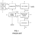
- FIG. 1 is a block diagram of a conventional power generation system.
- oxygen and a fuel such as methane
- a fuel such as methane
- the fuel is mixed with oxygen to be burned to generate a gas.
- the generated gas is supplied to a gas turbine 5.
- the gas turbine 5 causes a rotor to rotate by the gas supplied from the combustor 1, to generate electricity and to supply a spent gas to an exhaust-heat recovery boiler 6.
- a part of steam exhausted from the exhaust-heat recovery boiler 6 is supplied to a condenser 7, and the rest of steam is recovered by a steam turbine 8 or the combustor 1.
- carbon dioxide supplied from the exhaust-heat recovery boiler 6, together with the part of steam, is supplied to the condenser 7.
- Water discharged from the steam turbine 8 and water discharged from the condenser 7 are supplied to the exhaust-heat recovery boiler 6.
- the turbines 5 and 8 serve as power generating means.
- the combustor 1 receives oxygen from the oxygen tank 2, a fuel, such as methane, from the fuel tank 3 for storing the fuel therein, and steam from the exhaust-heat recovery boiler 6 to mix them to generate a mixed gas.
- the mixed gas is burned in the combustor 1.
- the burned mixed gas serves as a combustion gas of carbon dioxide and steam to be fed to the gas turbine 5.
- the combustion gas causes the gas turbine 5 to rotate the rotor to generate electric energy, which is supplied to consumers.
- Exhaust gases, such as steam and carbon dioxide, exhausted from the gas turbine 5 are fed to the exhaust-heat recovery boiler 6.
- the exhaust-heat recovery boiler 6 utilizes the heat of the exhaust gas fed from the gas turbine 5, to heat water condensed by the condenser 7 and water discharged from the steam turbine 8 to convert the water into steam.
- the condenser 7 cools the exhaust gas such as steam carbon dioxide, which is supplied from the exhaust-heat recovery boiler 6 to condense the exhaust gas into water.
- a part of the exhausted steam boiled by the heat of the exhaust-heat recovery boiler 6 is supplied to the combustor 1, and the rest of the steam is supplied to the steam turbine 8.
- the steam turbine 8 causes the supplied steam to rotate its rotor to take out electric energy from the steam. This energy is also supplied to electric power consumers.
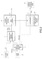
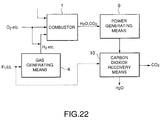
- a power generation system comprises: gas generating means for generating a gas containing at least hydrogen from a fuel; combustion means for receiving a fluid containing the gas supplied from the gas generating means, and a fluid containing, as a main component, oxygen or a compound containing at least one of carbon atom(s), hydrogen atom(s) and oxygen atom(s), to burn these fluids; power generating means for generating electricity using the fluids supplied from the combustion means; and carbon dioxide recovery means for recovering at least a part of carbon dioxide from the fluids supplied from the power generating means.
- a power generation system comprises: gas generating means 4 for reforming, decomposing or gasifying a fuel supplied from fuel supply means, such as a fuel tank 3, to generate a gas containing at least hydrogen; combustion means 1, such as a combustor, for receiving a fluid containing the gas supplied from the gas generating means 4, and a fluid containing, as a main component, a compound containing at least one of oxygen supplied from oxygen supply means, such as an oxygen tank 2, carbon atoms, hydrogen atoms and oxygen atoms, to burn these fluids; power generating means 9 for generating electricity using the fluids supplied from the combustion means 1; and carbon dioxide recovery means 10 for recovering at least a part of carbon dioxide from the fluids exhausted from the power generating means 9.
- the power generating means 9 may comprise, e.g., a gas turbine 5.
- the carbon dioxide recovery means 10 may comprise, e.g., a condenser 7. If necessary, carbon dioxide recovered by the carbon dioxide recovery means 10 is stored in a carbon dioxide storage tank 11 and processed so as not to be exhausted to atmosphere.
- the power generation system shown in FIG. 2 which serves as a basic concept of the present invention, contains the gas generating means 4 and the carbon dioxide recovery means 10.
- the carbon dioxide recovery means 10 may include the condenser 7 which is the same as that of the conventional power generation system.
- carbon dioxide (CO 2 ) and steam (H 2 O) are supplied to the condenser 7, directly or via the gas generating means, from the power generating means 9, although carbon dioxide (CO 2 ) and steam (H 2 O) are supplied to the condenser 7 via the exhaust heat recovery boiler 6 in the conventional power generation system shown in FIG. 1.
- both systems are different.
- the recovered carbon dioxide may be recycled in a circulating cycle of the power generation system if possible.
- the recovered carbon dioxide may be recycled as a secondary product in other industries by liquefying or solidifying (dry ice) the recovered carbon dioxide by cooling.
- the solidified carbon dioxide can be produced as a coolant or the like on a commercial basis.
- FIG. 3 is a block diagram of the second preferred embodiment of a power generation system according to the present invention.
- a power generation system is provided with a reformer 12 serving as the gas generating means 4.
- the second preferred embodiment is constructed so as to have a concrete construction in comparison with the first preferred embodiment.
- the carbon dioxide recovery means 10 comprises a condenser 7.
- the condenser 7 recovers carbon dioxide and cools steam to generate water (H 2 O). A part of the generated water is discharged, and the rest thereof is circulated to a gas turbine 5 to be recycled.
- the combustor 1 is connected to an oxygen tank 2 for storing oxygen therein, the reformer 12 (a gas generating section 4) for reforming a fuel of a carbon compound, such as methanol, to generate a reformed gas, and a gas turbine 5 (a power generation section) for taking out energy from a high-temperature gas.
- the reformed gas includes at least hydrogen, or hydrogen and carbon dioxide.
- the reformer 12 is provided with a fuel tank 3 for storing therein a fuel such as methanol. Combustion gas exhausted from the combustor 1 is fed to the reformer 12 via the gas turbine 5.
- the reformer 12 feeds a reformed gas, such as hydrogen which is obtained by reforming a fuel gas such as methanol, to the combustor 1, and carbon dioxide and steam to the condenser 7 (a carbon dioxide recovery section 10).
- the condenser 7 separates steam and carbon dioxide, which are fed from the reformer 12. Then, the condenser 7 discharges a part of condensed water to the reformer 12 and the rest of the condensed water to the outside of the power generation system. The separated carbon dioxide is recovered. The recovered carbon dioxide is liquefied.
- methanol serving as a fuel is supplied from the fuel tank 3, and water is supplied from the condenser 7.
- the ratio of the feed rates of methanol to water is 1 : 2.
- Hydrogen and carbon dioxide obtained by the aforementioned reaction are supplied to the combustor 1 to required amounts. Simultaneously, a part of unreacted excessive water, together with hydrogen and carbon dioxide, is also fed to the combustor 1. At the same time that hydrogen, carbon dioxide and steam are fed from the reformer 12 to the combustor 1, oxygen (usually air) is fed from the oxygen tank 2 to the combustor 1.
- Oxygen supplied from the oxygen tank 2, and hydrogen, carbon dioxide and steam supplied from the reformer 12 are mixed in the combustor 1 to be burned therein.
- the combustion gases, such as steam and carbon dioxide, burned in the combustor 1 are expanded. These combustion gases are fed to the gas turbine 5 to generate energy (electric power), which is taken out.
- steam and carbon dioxide which are exhaust gases from the gas turbine 5 are fed to the reformer 12. Since these exhaust gases have a very high temperature, the exhaust gases are used in the gas generating means 4 as heat sources for allowing a reforming reaction in the reformer 12 and for vaporizing steam or methanol. Steam and carbon dioxide supplied from the gas turbine 5 are fed to the condenser 7 after the heat thereof is absorbed.
- the condenser 7 separates carbon dioxide from steam.
- the separated carbon dioxide is fed to the carbon dioxide recovery section 10.
- the recovered carbon dioxide is liquefied to be recovered so as not to be exhausted to the outside.
- a part of the steam separated from carbon dioxide is condensed into a condensed water, which is supplied to the reformer 12 to be used again, and excessive steam is exhausted to the outside of the power generation system.
- the carbon component in the fuel gas is changed into carbon dioxide, it is possible to inhibit carbon particles and carbon monoxide from being produced due to incomplete combustion, so that it is possible to operate the power generation system for a long term.
- the combustible range of hydrogen is in the range of from 4 to 75 (vol%), which is wider than the combustible range of 5 to 15 (vol%) of methane gas, the combustible range of 2.1 to 9.5 (vol%) of propane gas and the combustible range of 6 to 36 (vol%) of methanol.
- the burning rate is 291 (cm/s), which is far greater than the burning rate of 37 (cm/s) of methane gas, the burning rate of 43 (cm/s) of propane gas and the burning rate of 55 (cm/s) of methanol. Therefore, hydrogen is relatively difficult to cause incomplete combustion so as not to produce unburned fuel residues, so that the power generation system has a long life.
- a compressor 13 is provided between a condenser 7 and a combustor 1, and carbon dioxide supplied from the condenser 7 is recovered to be supplied to the combustor 1 after compression.
- the combustor 1 is connected to: an oxygen tank 2 for storing oxygen therein; a reformer 12 (gas generating means 4) for reforming a fuel of a carbon compound, such as methanol, to generate a reformed gas; a compressor 13 for compressing carbon dioxide; and a gas turbine (power generating means 9) for taking energy out of a high-temperature gas.
- the reformed gas contains at least hydrogen, or hydrogen and carbon dioxide.
- a fuel is supplied from a fuel tank 3 for storing therein a fuel, such as methanol.
- the combustion gas supplied from the combustor 1 is fed to the reformer 12 via the gas turbine 5.
- a reformed gas such as hydrogen which is obtained by reforming the combustion gas such as methanol
- carbon dioxide and hydrogen fed from the gas turbine 5 are fed to the condenser 7.
- the condenser 7 (the carbon dioxide recovery means 10) separates steam and carbon dioxide which are fed from the reformer 12. A part of the condensed water is fed to the reformer 12, and the rest of water is discharged. The separated carbon dioxide is fed to the compressor 13. A part of the carbon dioxide fed to the compressor 13 is compressed, and then, fed to the combustor 1. The rest of carbon dioxide is recovered. The recovered carbon dioxide is liquefied to be stored.
- methanol serving as a fuel is supplied from the fuel tank 3, and water is supplied from the condenser 7.
- the ratio of the feed rates of methanol to water is 1 : 2.
- the chemical reaction expressed by the following formula (I) occurs to generate hydrogen and carbon dioxide.
- Hydrogen and carbon dioxide obtained by such a reaction are supplied to the combustor 1 to required amounts, and a part of unreacted excessive water (steam) is also fed to the combustor 1.
- hydrogen, carbon dioxide and steam are fed from the reformer 12, and oxygen (usually air) is fed from the oxygen tank 2. Also, carbon dioxide is supplied from the compressor 4 to the combustor 1.
- the oxygen supplied from the oxygen tank 2, the hydrogen, carbon dioxide and steam supplied from the reformer 12, and the carbon dioxide supplied from the compressor 13 are mixed in the combustor 1 to be burned therein.
- the combustion gas of steam and carbon dioxide burned in the combustor 1 is expanded. This combustion gas is fed to the gas turbine 5 to generate energy (electric power), which is taken out.
- steam and carbon dioxide which are exhaust gases from the gas turbine 5 are fed to the reformer 12. Since these exhaust gases have a very high temperature, these gases serve as heat sources for allowing a reforming reaction in the reformer 12 and for vaporizing water or methanol.
- Steam and carbon dioxide exhausted from the gas turbine 5 are fed to the condenser 7 after the heat thereof is absorbed in the reformer 12.
- the condenser 7 separates carbon dioxide from steam. A part of the separated carbon dioxide is fed to the compressor 13 to be compressed therein, and then, fed to the combustor 1. The rest of the carbon dioxide is liquefied to be recovered. Therefore, the carbon dioxide is not exhausted to the outside of the power generation system, so that carbon dioxide is not emitted to atmosphere.
- a part of the steam separated from carbon dioxide is condensed into a condensed water to be supplied to the reformer 12, and the rest of the steam is exhausted to the outside of the power generation system.
- the combustible range of hydrogen is in the range of from 4 to 75 (vol%), which is wider than the combustible range of from 5 to 15 (vol%) of the methane gas, the combustible range of from 2.1 to 9.5 (vol%) of propane gas and the combustible range of from 6 to 36 (vol%) of methanol.
- the burning rate of hydrogen is 291 (cm/s), which is far greater than the burning rate of 37 (cm/s) of methane gas, the burning rate of 43 (cm/s) of propane gas and the burning rate of 55 (cm/s) of methanol. Therefore, hydrogen is relatively difficult to cause incomplete combustion so as to inhibit the production of unburned fuel residues, so that the power generation system has a long life.
- the fuel is changed to hydrogen and carbon dioxide, the production of by-products such as alcohols, e.g., formaldehyde, is inhibited. Therefore, the safety of the power generation system can be improved since it is safe for human beings.
- at least a part of the carbon dioxide recovered by the condenser 7 is supplied to the combustion chamber 1 via the compressor 13, so that it is possible to prevent carbon dioxide, which produces acid rain and causes the earth anathermal phenomenon to deteriorate the global environment, from being exhausted to atmosphere. Thus, it is possible to increase the quantity of energy taken out of the gas turbine 5.
- the present invention should not be limited to the power generation systems in the first through third preferred embodiment, and it should be appreciated that the invention can be embodied in various ways without departing from the principle of the invention.
- the water separated by the carbon dioxide recovery section to be discharged to the outside of the power generation system may be used for cooling the gas generation section, the combustor and the power generating means.
- sea water may be used as a heat sink for cooling the fluid supplied from the combustor to the carbon dioxide recovery section.
- a part of the carbon dioxide fed from the compressor 13 may be used for cooling the power generating means 9.
- a power generation system is characterized in that a fuel is gasified to be supplied to a combustor in order to reform and decompose the fuel, and carbon dioxide supplied from power generating means is recovered in a circulating cycle of the power generation system to inhibit carbon dioxide from being emitted to atmosphere.
- the present invention may include various modifications having the aforementioned characteristics. In order to disclose such various modifications, a principal part of the fourth through twenty-fourth preferred embodiment of a power generation system, according to the present invention, will be described below.
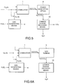
- FIG. 5 is a block diagram of a principal part of the fourth preferred embodiment of a power generation system according to the present invention.
- gas generating means 4 At least a part of a fuel stored in a fuel tank (not shown) is supplied to gas generating means 4.
- gas generating means 4 a gas containing at least hydrogen is produced from the fuel.
- a fluid containing the gas exhausted from the gas generating means is supplied to a combustor 1.
- a fluid containing, as a main component, oxygen or a compound containing carbon atom(s) and/or hydrogen atom(s) and/or oxygen atom(s) is supplied to the combustor 1.
- the oxygen supplied to the combustor 1 may be liquid or gas, the oxygen is preferably liquid in a case where it is stored.
- the oxygen contained in the fluid which is supplied to the combustor 1, may be oxygen generated by electrolyzing water, or oxygen generated by vapor-phase separating air into nitrogen and oxygen. This method is called as a membrane separating method or an osmosis refrigeration method.
- the fluid containing the gas exhausted from the gas generating means 4 and the fluid containing, as a main component, oxygen or a compound of carbon atom(s) and/or hydrogen atom(s) and/or oxygen atom(s), may be mixed in the combustor 1 or mixed before being supplied to the combustor 1.
- the high-temperature fluid supplied from the combustor 1 is introduced into power generating means 9.
- the power generating means 9 generates electricity by expanding the introduced high-temperature fluid in the power generating means 9.
- the fluid supplied from the power generating means 9 is supplied to the carbon dioxide recovery means 10. At least a part of carbon dioxide contained in the fluid, which is exhausted from the power generating means 9, is recovered by the carbon dioxide recovery means 10.
- the power generation system comprises the gas generating means 4, the combustor 1, the power generating means 9 and the carbon dioxide recovery means 10.
- the fuel supplied to the gas generating means 4 is a compound containing carbon and hydrogen.
- it may contain at least one of methanol, ethanol, methane, ethane, propane, butane, dimethyl ether, petroleum, carbon monoxide and formic acid.
- methanol can generate a gas containing at least hydrogen at a temperature of about 300°C which is a relatively low temperature in power plants.
- a temperature of about 900°C is required.
- a gas containing hydrogen is generated by allowing a shift-reaction (reforming) of the aforementioned fuel, or by decomposing or gasifying the aforementioned fuel.
- a shift-reaction for example, if the fuel is methanol, a gas containing hydrogen is generated by the reforming reaction or decomposition. If the fuel is coal, it is gasified to generate carbon monoxide, and the shift reaction of the generated carbon monoxide is allowed to generate a gas containing hydrogen.
- the gases supplied from the gas generating means 4 are hydrogen and carbon dioxide (reforming reaction).
- the hydrogen and carbon dioxide generated by the gas generating means 4 are supplied to the combustor 1.
- the gas generated by the gas generating means 4 may contain at least hydrogen.
- hydrogen and carbon dioxide are supplied to the combustor 1.
- the hydrogen and carbon dioxide generated by the gas generating means 4 may be mixed with water or oxygen in a storage tank (not shown) before being supplied to the combustor 1. As mentioned above, water or steam may be directly supplied to the combustor 1 even if it is not mixed with the gas generated by the gas generating means 4 before being supplied to the combustor 1.
- the hydrogen and carbon dioxide generated by the gas generating means 4 and the fluid containing, as a main component, oxygen or a compound containing carbon atom(s) and/or oxygen atom(s) and/or hydrogen atom(s) are burned. Also in a case where water or steam is mixed with hydrogen and oxygen supplied to the combustor 1, it is burned with oxygen.
- the carbon dioxide and steam supplied from the power generating means 9 are fed to the carbon dioxide recovery means 10.
- the steam is liquefied, i.e., condensed, to be separated into a gas and a liquid, specifically into carbon dioxide and water, and the carbon dioxide being a gas is recovered.
- the processes for separating steam into a gas and a liquid contain chemisorption processes, physical absorption processes, absorption processes, membrane separation processes and so forth.
- the chemisorption processes contain, e.g., the Alkanol amine process and the hot potassium carbonate process.
- the fourth preferred embodiment since most of carbon atoms contained in the fuel are changed to carbon dioxide, it is possible to inhibit carbon particles and carbon monoxide from being generated due to incomplete combustion. Therefore, it is possible to increase the life of the power generation system by inhibiting carbon atoms from being deposited, and it is possible to provide a power generation system suitable for a favorable global environment by inhibiting carbon monoxide from being generated.
- the combustible range of hydrogen generated by the gas generating means 4 is in the range of from 4 to 75 (vol%), which is wider than 5 to 15 (vol%) of the methane gas, 2.1 to 9.5 (vol%) of propane gas and 6 to 36 (vol%) of methanol.
- the burning rate of hydrogen is 291 (cm/s), which is far greater than 37 (cm/s) of methane gas, 43 (cm/s) of propane gas and 55 (cm/s) of methanol. Therefore, since hydrogen is relatively difficult to cause incomplete combustion, it is possible to inhibit unburned fuel residues from being produced, so that the power generation system can have a long life.
- the fuel is changed to at least hydrogen and carbon dioxide by the gas generating means 4, the production of by-products, such as alcohols, e.g., formaldehyde, is inhibited. Therefore, the safety of the power generation system can be improved since it is safe for human beings.
- by-products such as alcohols, e.g., formaldehyde
- the fluid supplied by the combustor 1 consists of carbon dioxide and steam (or water)
- the vapor-liquid separation of carbon dioxide from water is easily carried out, so that it is possible to improve the separation efficiency. It is also possible to decrease the costs and size of the carbon dioxide recovery means 10.
- power generating means 9 comprises a gas turbine 5 and/or a steam turbine 8.
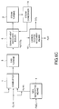
- FIGS. 6A through 6C are block diagrams, each of which illustrates a principal part of the fifth preferred embodiment of a power generation system according to the present invention, wherein the power generating means 9 is a gas turbine 5 in FIG. 6A, a steam turbine 8 in FIG. 6B, and a combined system of the gas turbine 5 and the steam turbine 8 in FIG. 6C.
- the power generating means 9 is a gas turbine 5 in FIG. 6A, a steam turbine 8 in FIG. 6B, and a combined system of the gas turbine 5 and the steam turbine 8 in FIG. 6C.
- the power generating means 9 is the gas turbine 5.
- a fluid supplied from the combustor 1 is introduced into the gas turbine 5 to generate electricity.
- the power generating means 9 is the steam turbine 8.
- Steam (a working fluid) supplied to the steam turbine 8 is generated using the heat of a fluid exhausted from the combustor 1.
- an exhaust-heat recovery boiler 6 is provided between the combustor 1 and carbon dioxide recovery means 10. Water is heated by the heat of the fluid supplied from the combustor 1 to generate steam.
- the generated steam is introduced into the steam turbine 8 as a working fluid to generate electricity.
- the fluid supplied from the steam turbine 8 is condensed by means of a steam condenser 14 to be supplied to the exhaust-heat recovery boiler 6 again.
- the power generating means 6 comprises a combined system using the gas turbine 5 and the steam turbine 8.
- the fluid supplied from the combustor 1 is introduced into the gas turbine 5 to generate electricity.
- the heat exchange is carried out.
- the heat of the fluid supplied from the gas turbine 5 is used for generating steam, which is introduced into the steam turbine 8, by means of the exhaust-heat recovery boiler 6.
- the steam generated by heating water by the heat exchange is introduced into the steam turbine 8 to generate electricity.
- the power generating means 9 may be any one of constructions for generating electricity, such as the gas turbine 5 and the steam turbine 8.
- the power generating means 9 may be a thermoelectric generator.
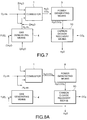
- FIG. 7 is a block diagram of a principal part of the sixth preferred embodiment of a power generation system, according to the present invention, which includes a water or steam receiving portion in addition to the power generation system.
- a fuel or a gas containing at least hydrogen may be mixed with water or steam at any one or more of the following four locations. Water and steam is stored in a storage portion (not shown) or the like.
- a fuel or a gas containing at least hydrogen may be mixed with water or steam, may be.
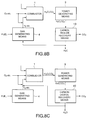
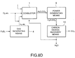
- FIGS. 8A through 8D the seventh preferred embodiment of a power generation system, according to the present invention, will be described below.
- FIGS. 8A through 8D are block diagrams, each of which illustrates a principal part of the seventh preferred embodiment of a power generation system according to the present invention.
- this preferred embodiment at least a part of water or steam recovered by carbon dioxide recovery means 10 is supplied.
- various modifications of the sixth preferred embodiment of the power generation system shown in FIG. 7 are described.
- a fuel or a gas containing at least hydrogen is mixed with water or steam stored in a storage portion without circulating water or steam generated in a power generation system.
- FIGS. 8A through 8D at least a part of water or steam generated in a power generation system, i.e., recovered by carbon dioxide recovery means 10, is mixed with a fuel supplied to gas generating means 4, or with a gas containing at least hydrogen supplied to a combustor 1.
- the supplied locations are the same as those of FIG. 7.
- a fuel or a gas containing at least hydrogen may be mixed with water or steam at any one or more of the following four locations.
- a fuel or a gas containing at least hydrogen may be mixed with water or steam at any one or more of the aforementioned locations 1 ⁇ - 4 ⁇ .
- the seventh preferred embodiment it is possible to supply water or steam by mixing a fuel with water or steam when the fuel is insufficient in the combustor 1. It is also possible to increase the generated energy by increasing the quantity of fluid supplied to the gas turbine 5. In addition, excessive heat produced by combustion in the combustor 1 can be removed to cool the combustor 1 by water or steam. Moreover, it is not required to provide any storage portions for storing water or steam therein, and it is possible to improve the efficiency of the power generation system by recycling water or steam.
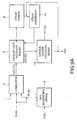
- FIGS. 9A and 9B the construction and operation of the eighth preferred embodiment of a power generation system, according to the Present invention, will be described below.
- FIGS. 9A and 9B are block diagrams, each of which illustrates a principal part of the eighth preferred embodiment of a power generation system according to the present invention. As shown in FIGS. 9A and 9B, at least a part of water or steam recovered by carbon dioxide recovery means 10 may be supplied as a working fluid for a steam turbine 8.
- FIG. 10 is a block diagram of the ninth preferred embodiment of a power generation system according to the present invention.
- a fuel supplied to gas generating means 4 is reformed, decomposed or gasified by the heat of a fluid exhausted from a combustor 1. All or a part of the fluid exhausted from the combustor 1 may be supplied to the gas generating means 4 when the fuel is reformed, decomposed or gasified.
- the exhaust heat of the gas exhausted from the combustor 1 is used as a heat source for reforming, decomposing or gasifying the fuel, it is not required to provide an additional heat source, and it is possible to effectively utilize the exhaust heat.
- FIGS. 11A through 11C the construction and operation of the tenth preferred embodiment of a power generation system, according to the present invention, will be described below.
- FIGS. 11A through 11C are block diagrams, each of which illustrates the tenth preferred embodiment of a power generation system according to the present invention.
- a fuel supplied to gas generating means 4 is reformed, decomposed or gasified by the heat of a fluid extracted from a gas turbine 5 or a steam turbine 8.
- the fluid extracted from the gas turbine 5 (FIG. 11A), the fluid extracted from the steam turbine 8 (FIG. 11B), or the fluid extracted from the gas turbine 5 and the fluid extracted from the steam turbine 8 (FIG. 11C) may be all or a part of the fluid in the gas turbine 5 or the steam turbine 8 if the fuel supplied to the gas generating means 4 is reformed, decomposed or gasified.
- the exhaust heat of the fluid exhausted from the gas turbine 5 or the steam turbine 8 is used as a heat source for reforming, decomposing or gasifying a fuel, it is not required to provide an additional heat source, and it is possible to effectively utilize the exhaust source.
- FIGS. 12A thorough 12D the construction or operation of the eleventh preferred embodiment of a power generation system, according to the present invention, will be described below.
- FIG. 12A through 12D are block diagrams, each of which illustrates the eleventh preferred embodiment of a power generation system, according to the present invention, will be described below.
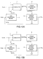
- at least a part of carbon dioxide separated and recovered by carbon dioxide recovery means 10 are supplied to gas generation means 4 or a combustor 1.
- Carbon dioxide may be supplied at any one or more the following four locations.
- a fuel or a gas containing at least hydrogen may be mixed with carbon dioxide at any one or more of the aforementioned locations 1 ⁇ - 4 ⁇ .
- the eleventh preferred embodiment it is possible to supply carbon dioxide required for combustion in the combustor 1, by mixing a fuel with carbon dioxide. It is also possible to increase the quantity of the fluid, which is supplied to the gas turbine 5, to increase the generated energy. Moreover, excessive heat produced by combustion in the combustor 1 can be removed to cool the combustor 1 by supplying carbon dioxide to the gas containing at least hydrogen.
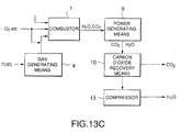
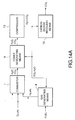
- FIGS. 13A through 13D the construction and operation of the twelfth preferred embodiment of a power generation system, according to the present invention, will be described below.
- FIGS. 13A through 13D are block diagrams, each of which illustrates a principal part of the twelfth preferred embodiment of a power generation system according to the present invention.
- a compressor 13 (or pump) may be provided between power generating means 9 and carbon dioxide recovery means 10.
- the compressor 13 compresses a fluid supplied from the power generating means 9 to supply a compressed fluid to the carbon dioxide recovery means 10.
- a compressor 13 may be provided downstream of carbon dioxide recovery means 10.
- carbon dioxide is compressed
- water is compressed
- both of carbon dioxide and steam are compressed.
- the carbon dioxide or water recovered by carbon dioxide recovery means 10 is compressed by the compressor 13, so that the recovery of carbon dioxide or steam can be improved.
- the compressor 13 may compress a fluid containing at least carbon dioxide, which is produced in the power generation system, to a desired pressure, and a plurality of compressors 13 may be provided in the power generation system if necessary.
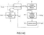
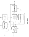
- FIGS. 14A through 14D the construction and operation of the thirteenth preferred embodiment of a power generation system, according to the present invention, will be described below.
- FIGS. 14A through 14D are block diagrams, each of which illustrates a principal part of the thirteenth preferred embodiment of a power generation system according to the present invention.
- a compressed fluid carbon dioxide, steam
- a compressor 13 provided between power generating means 9 and carbon dioxide recovery means 10
- gas generating means 4 or a combustor 1
- the compressed fluid can be supplied to the combustor 1 as a coolant, so that it is possible to prevent the temperature in the combustor 1 from rising to a temperature higher than a required temperature.
- a compressed fluid (carbon dioxide) supplied from a compressor 13 provided downstream of carbon dioxide recovery means 10 may be supplied to gas generating means 4 or a combustor 1, so that the amount of a fluid in the combustor 1 can be increased.
- the compressed fluid can be supplied to the combustor 1 as a coolant, so that it is possible to prevent the temperature in the combustor 1 from rising to a temperature higher than a required temperature.
- a compressed fluid (steam) supplied from a compressor 13 provided downstream of carbon dioxide recovery means 10 may he supplied to gas generating means 4 or a combustor 1, so that the amount of a fluid in the combustor 1 can be increased.
- the compressed fluid can be supplied to the combustor 1 as a coolant, so that it is possible to prevent the temperature in the combustor 1 from rising to a temperature higher than a required temperature.
- a compressed fluid (carbon dioxide, steam) supplied from a compressor 13 provided downstream of carbon dioxide recovery means 10 may be supplied to gas generating means 4 or a combustor 1, so that the amount of a fluid in the combustor 1 can be increased.
- the compressed fluid can be supplied to the combustor 1 as a coolant, so that it is possible to prevent the temperature in the combustor 1 from rising to a temperature higher than a required temperature.
- the fluid (carbon dioxide, steam) supplied from the compressor 13 may be directly mixed with a fuel supplied to the gas generating means 4, or with a gas containing hydrogen supplied to the combustor 1. In a case where the compressed fluid is supplied to the gas generating means 4, it serves as a heat source required to reform, decompose or gasify the fuel.
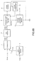
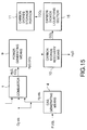
- FIG. 15 is a block diagrams of a principal part of the fourteenth preferred embodiment of a power generation system according to the present invention.
- a carbon dioxide liquefying section 15 for liquefying carbon dioxide exhausted from carbon dioxide recovery means 10 is provided. Carbon dioxide can be easily liquefied, and the liquefied carbon dioxide can be easily treated.
- the carbon dioxide liquefying section 15 is provided with a carbon dioxide storage portion 11 for storing the liquefied carbon dioxide. If the carbon dioxide storage portion 11 is provided, the liquefied carbon dioxide may be stored if necessary.
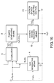
- FIG. 16 is a block diagrams of a principal part of the fifteenth preferred embodiment of a power generation system according to the present invention.
- the cold of a liquid oxygen liquefied and supplied to a combustor 1 the heat of vaporization of a fuel or the heat of vaporization of water is used as a heat sink for a carbon dioxide liquefying section 15. It is not required to provide an additional heat sink for liquefying carbon dioxide, so that it is possible to improve the thermal efficiency of the power generation system, and it is also possible to decrease the costs and size of the power generation system. If water (containing steam) generated in the power generation system is used for a heat sink, the power efficiency can be improved.
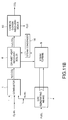
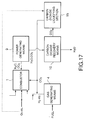
- FIG. 17 is a block diagrams of a principal part of the sixteenth preferred embodiment of a power generation system according to the present invention.
- a carbon dioxide liquefying section 15 is supplied to a combustor 1.
- the liquefied carbon dioxide supplied to the combustor 1 is heated in the combustor 1 to be vaporized, so that the amount of a fluid in the combustor 1 can be increased.
- the liquefied carbon dioxide can be supplied to the combustor 1 as a coolant, and it is possible to prevent the temperature in the combustor 1 from increasing to a temperature higher than a required temperature.
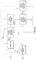
- FIG. 18 is a block diagrams of a principal part of the seventeenth preferred embodiment of a power generation system according to the present invention.
- a carbon dioxide vaporizing section 16 is provided between a combustor 1 and power generating means 9.
- At least a part of liquefied carbon dioxide is supplied from a carbon dioxide liquefying section 15 to the carbon dioxide vaporizing section 16.
- the liquefied carbon dioxide is heated by the heat of a fluid supplied from the combustor 1, so that the liquefied carbon dioxide is vaporized and expanded to be supplied to the combustor 1.
- the amount of a fluid supplied to the power generating means 9 can be increased by the vaporized carbon dioxide supplied to the combustor 1.
- the energy generated by the power generating means 9 can he increased by increasing the amount of the fluid supplied to the power generating means 9.
- the carbon dioxide can be supplied to the combustor 1 as a coolant, so that it is possible to prevent the temperature in the combustor 1 from rising to a temperature higher than a required temperature.
- FIG. 19 is a block diagrams of a principal part of the eighteenth preferred embodiment of a power generation system according to the present invention.
- the cold of liquid oxygen supplied to a combustor 1 or carbon dioxide liquefied by a carbon dioxide liquefying section 15 is used for cooling a steam condenser 14 provided in a steam turbine 8. If the cold of liquid oxygen or liquid carbon dioxide is used for cooling steam in the condenser 14, the cooling (condensation) can be effectively carried out without the need of an additional cooling unit.
- FIG. 20 is a block diagrams of a principal part of the nineteenth preferred embodiment of a power generation system according to the present invention.
- a fluid supplied from a combustor 1 to carbon dioxide recovery means 10 can be cooled (i.e., steam can be condensed) using the cold of liquefied oxygen supplied to the combustor 1. If the cold of liquefied oxygen is used, it is possible to effectively utilize the heat in the power generation system without the need of an additional heat sink unit.
- FIG. 21 is a block diagrams of a principal part of the twentieth preferred embodiment of a power generation system according to the present invention.
- a fluid supplied from a combustor 1 to carbon dioxide recovery means 10 can be cooled (i.e., steam can be condensed) using the cold of carbon dioxide liquefied by a carbon dioxide liquefying section 15. If the cold of liquefied carbon dioxide is used, it is possible to effectively utilize the heat in the power generation system without the need of an additional heat sink unit.
- FIG. 22 is a block diagrams of a principal part of the twenty-first preferred embodiment of a power generation system according to the present invention.
- a fluid supplied from a combustor 1 to carbon dioxide recovery means 10 can be cooled (i.e., steam can be condensed) using the heat of vaporization of a fuel (e.g., methanol). If the heat of vaporization of the fuel is used, it is possible to effectively utilize the heat in the power generation system without the need of an additional heat sink unit.
- a fuel e.g., methanol
- FIG. 23 is a block diagrams of a principal part of the twenty-second preferred embodiment of a power generation system according to the present invention.
- a fluid supplied from a combustor 1 to carbon dioxide recovery means 10 can be cooled (i.e., steam can be condensed) using the heat of vaporization produced when the pressure of water supplied to a pressure reducing section 17 is reduced. Since water is used as a cold source, the costs can be reduced and the handling can be easy.
- FIG. 24 is a block diagrams of a principal part of the twenty-third preferred embodiment of a power generation system according to the present invention.
- a gas flow-rate control section 18 for measuring and controlling the flow rate of a fluid containing a gas supplied from gas generating means 4.
- an oxygen flow-rate control section 19 for measuring and controlling the flow rate of oxygen contained in a fluid, which contains, as a main component, oxygen or a compound consisting of carbon atom(s), hydrogen atom(s) or oxygen atom(s).
- the flow rate of the fluid containing a gas is measured by the gas flow-rate control section 18, and the flow rate of oxygen to be supplied to a combustor 1 may be controlled by the oxygen flow-rate control section 19 so as to correspond to the measured flow-rate value of the fluid.
- the flow rate of oxygen may be measured by the oxygen flow-rate control section 19, and the flow rate of the fluid containing a gas to be supplied to the combustor 1 may be controlled by the gas flow-rate control section 18 so as to correspond to the measured flow-rate value of oxygen.
- the flow rate of oxygen contained in a fluid containing, as a main component, oxygen or a compound consisting of carbon atom(s) and/or hydrogen atom(s) and/or oxygen atom(s) is controlled on the basis of a stoichiometric mixture ratio as expressed by the following formula (4). (4 x +1 y -2 z )/4
- the flow rate of a fluid containing a gas and the flow rate of oxygen contained in a fluid are controlled by the gas flow-rate control section 18 and the oxygen flow-rate control section 19 on the basis of the formula (4), so that the power generating efficiency can be optimized and incomplete combustion can be inhibited. If the incomplete combustion is inhibited, it is possible to by-products from being deposited, so that it is possible to provide a safe power generation system which does not have a bad influence on the global atmosphere.
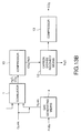
- FIG. 25 is a block diagrams of a principal part of the twenty-fourth preferred embodiment of a power generation system according to the present invention.
- a carbon dioxide flow-rate measuring section 20 is provided between a combustor 1 and a compressor 13.
- the flow rate of carbon dioxide of a fluid supplied from the compressor 13 is measured by the carbon dioxide flow-rate measuring section 20.
- the measured value is fed to an oxygen flow-rate controlling section 19.
- the oxygen flow-rate measuring section 19 controls the flow rate of oxygen contained in a fluid, which is supplied to the combustor 1 and which contains, as a main component, oxygen or a component consisting of carbon atom(s) and/or hydrogen atom(s) and/or oxygen atom(s).
- the flow rate of a fluid containing a gas, the flow rate of oxygen contained in a fluid, which contains, as a main component, oxygen or a component consisting of carbon atom(s) and/or hydrogen atom(s) and/or oxygen atom(s), and the flow rate of carbon dioxide contained in a fluid supplied from the compressor 13 are controlled by the gas flow-rate control section 18, the oxygen flow-rate control section 19 and the carbon dioxide flow-rate control section 20 on the basis of the formula (4), so that the power generating efficiency can be optimized and incomplete combustion can be inhibited. If the incomplete combustion is thus inhibited, it is possible to inhibit by-products from being deposited by power generation, so that it is possible to provide a safe power generation system which does not have a bad influence on the global atmosphere.
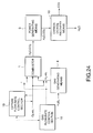
- FIG. 26 is a block diagram of the twenty-fifth preferred embodiment of a power generation control system according to the present invention.
- combustion means 1, gas generating means 4, power generating means 9, carbon dioxide recovery means 10 and so forth have the same constructions as those in the preceding preferred embodiments.
- the flows of oxygen, a fuel, hydrogen, carbon dioxide, water, energy and so forth are expressed by thick arrows in FIG. 26.
- a power generation control system includes: oxygen supply means 2 comprising, e.g., an oxygen tank, an oxygen supply valve and so forth; fuel supply means 3 comprising a fuel tank, a fuel supply valve and so forth; control means 21 for controlling the operations of the combustion means 1, the power generating means 9, the carbon dioxide recovery means 10 and so forth; and output detecting means 22 for detecting the output of electric energy generated by the power generating means 9.
- a target output is inputted to the control means 21, and actual energy generated by the power generating means 9 is detected by the output detecting means 22.
- the control means 21 determines the feed rates of the fuel, oxygen and so forth and controls combustion in the combustion means 1.
- the energy generated by the power generating means 9 can be controlled, and the amount of the recovered carbon dioxide, which is most important in the present invention, can be detected and controlled.
- the most effective amount of the recovery carbon dioxide is calculated at the input target output, and the amount of the recovery carbon dioxide is controlled so that the amount of carbon dioxide emitted to atmosphere is minimum.
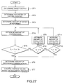
- FIG. 27 a process for controlling the twenty-sixth preferred embodiment of a power generation system, according to the present invention, will be described below. Furthermore, the control process shown in FIG. 27 may be applied to the power generation control system shown in FIG. 26.
- a target output is determined at step ST1.
- the feed rates of oxygen and a fuel are determined (step ST2).
- the amount of water in a reformer serving as gas generating means is determined (step ST3), and the amount of hydrogen gas supplied from the reformer is determined (step ST4).
- the amount of recovered carbon dioxide is determined at step ST6.
- various valves are controlled (step ST7), so that carbon dioxide is recovered in a usual power generating state to inhibit carbon dioxide from being emitted.
- step ST8 When it is determined at step ST5 that the target temperature is beyond the desired scope, it is determined whether the target temperature is lower than the minimum temperature (step ST8). When it is determined the target temperature is lower than the minimum temperature, the amounts of the circulated carbon dioxide and oxygen are decreased, and the routine is repeated from the step ST3. When it is determined at step ST8 that the target temperature exceeds the minimum temperature, it is determined again whether the target temperature exceeds the maximum temperature (step ST10). When it is determined that the target temperature does not exceed the maximum temperature, the routine goes to step ST6. When it is determined at step ST10 that the target temperature exceeds the maximum temperature, it is reset so that the amounts of the circulated carbon dioxide and water are decreased (step ST11). Then, the routine goes from step ST11 to step ST3, and the processes of steps ST4 through ST7 are repeated.
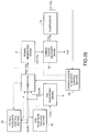
- the present invention is not limited in the constitution and may comprise a component without the gas generating means such as a power generation system according to the twenty-seventh embodiment shown in FIG. 28.
- the power generation system comprises a combustor 1 for receiving and burning a fluid containing at least hydrogen and a fluid containing, as a main component, oxygen or a compound containing atoms selected from the group consisting of carbon, hydrogen or oxygen, power generating means 9 for generating electricity using a fluid supplied from the combustor 1, and carbon dioxide recovery means 10 for recovering at least a part of carbon dioxide from a fluid supplied from the power generating means 9.
- the carbon dioxide recovery means 10 liquefies steam to separate the steam into a gas and liquid.
- the carbon dioxide recovery means 10 is connected to a carbon dioxide liquefying section 15 for requefying a fluid containing carbon dioxide exhausted from the carbon dioxide recovery means 10.
- the power generation system according to twenty-seventh embodiment further comprises carbon dioxide storage means 11 for storing carbon dioxide liquefied by the carbon dioxide liquefying section 15.
- carbon dioxide liquefied and stored in the storage means 11 is composed with hydrogen supplied from another section to reform a fuel such as a methanol when the occasion demands.
- a fuel such as a methanol
- the reformed methanol and the like is used as a fuel for the power generating means.
Abstract
Description
Claims (27)
- A power generation system comprising:gas generating means for reforming, decomposing or gasifying a fuel to generate a gas containing at least hydrogen;combustion means for receiving and burning a fluid containing the gas supplied from the gas generating means and a fluid containing, as a main component, oxygen or a compound containing atoms selected from the group consisting of carbon, hydrogen and oxygen atoms and the combinations thereof;power generating means for generating electricity using a fluid supplied from the combustion means; andcarbon dioxide recovery means for recovering at least a part of carbon dioxide from a fluid exhausted from the power generating means.
- A power generation system as set forth in claim 1, wherein said fuel is a compound containing carbon or hydrogen, said fuel being selected from the group consisting of methanol, ethanol, methane, ethane, propane, butane, dimethyl ether, diethyl ether, coal, carbon monoxide, formic acid and the mixture thereof.
- A power generation system as set forth in claim 2, wherein at least a part of water or steam recovered by said carbon dioxide recovery means is supplied to a steam turbine serving as said power generating means.
- A power generation system as set forth in claim 1, wherein said oxygen contains at least oxygen obtained by decomposing water or separating air.
- A power generation system as set forth in claim 1, wherein said oxygen is liquid oxygen.
- A power generation system as set forth in claim 5, wherein a fluid supplied from said combustion means and supplied to said carbon dioxide recovery means is cooled by said liquid oxygen, liquefied carbon dioxide, or heat of vaporization of said fuel or water.
- A power generation system as set forth in claim 1, wherein said fluid containing the gas supplied from the gas generating means is mixed with said fluid containing, as a main component, oxygen or a compound containing atoms selected from the group consisting of carbon, hydrogen and oxygen atoms and the combinations thereof, before said fluids are supplied to said combustion means.
- A power generation system as set forth in claim 1, wherein said carbon dioxide recovery means liquefies steam to separate the steam into a gas and a liquid.
- A power generation system as set forth in claim 8, wherein a fluid supplied from said combustion means and supplied to said carbon dioxide recovery means is cooled by said liquid oxygen, liquefied carbon dioxide, or heat of vaporization of said fuel or water.
- A power generation system as set forth in claim 1, wherein said power generating means contains at least one of a gas turbine and a steam turbine.
- A power generation system as set forth in claim 10, wherein a working fluid supplied to said steam turbine is heated by the heat of a fluid supplied from said combustion means.
- A power generation system as set forth in claim 1, wherein water or steam is supplied to any one of said combustion means and said gas generating means.
- A power generation system as set forth in claim 1, wherein at least a part of water or steam recovered by said carbon dioxide recovery means is supplied to at least one of said combustion means and said gas generating means.
- A power generation system as set forth in claim 13, wherein said fuel supplied to said gas generating means is reformed, decomposed or gasified by the heat of a fluid supplied from said combustion means.
- A power generation system as set forth in claim 13, wherein said fuel supplied to said gas generating means is reformed, decomposed or gasified by the heat of a fluid extracted from said gas turbine or said steam turbine.
- A power generation system as set forth in claim 1, wherein said carbon dioxide recovered by said carbon dioxide recovery means is supplied to at least one of said gas generating means and said combustion means.
- A power generation system as set forth in claim 1, which further comprises a compressor for compressing a fluid containing carbon dioxide.
- A power generation system as set forth in claim 17, wherein a fluid exhausted from said compressor is supplied to at least one of said combustion means and said gas generating means.
- A power generating means as sat forth in claim 1, which further comprises a carbon dioxide liquefying section for liquefying a fluid containing carbon dioxide exhausted from said carbon dioxide recovery means.
- A power generating means as set forth in claim 19, which further comprises carbon dioxide storage means for storing carbon dioxide liquefied by said carbon dioxide liquefying section.
- A power generation system as get forth in claim 21, wherein a fluid exhausted from said combustion means and supplied to said carbon dioxide recovery means is cooled by said liquid oxygen, liquefied carbon dioxide, or heat of vaporization of said fuel or water.
- A power generation system as set forth in claim 1, which further comprises:a gas flow-rate control section for controlling a flow rate of a fluid containing a gas supplied from said gas generating means and supplied to said combustion means;an oxygen flow-rate control section for controlling a flow rate of oxygen contained in said fluid supplied to said combustion means, said fluid containing, as a main component, oxygen or a compound containing atoms selected from the group consisting of carbon, hydrogen and oxygen atoms and the combinations thereof; andcontrol means for controlling a flow rate of oxygen or a fuel so as to correspond to said flow rate of said fluid containing a gas or said oxygen.
- A power generation system as set forth in claim 21, wherein said control means controls said gas flow-rate control section arid said oxygen flow-rate control section so that said flow rate of said oxygen is
- A power generation system comprising:combustion means for receiving and burning a fluid containing at least hydrogen and a fluid containing, as a main component, oxygen or a compound containing atoms selected from the group consisting of carbon, hydrogen or oxygen;power generating means for generating electricity using a fluid supplied from said combustion means; andcarbon dioxide recovery means for recovering at least a part of carbon dioxide from a fluid supplied from said power generating means.
- A power generation system as set forth in claim 24, wherein said carbon dioxide recovery means liquefies steam to separate the steam into a gas and a liquid.
- A power generation system as set forth in claim 24, further comprising a carbon dioxide liquefying section for requefying a fluid containing carbon dioxide exhausted from said carbon dioxide recovery means.
- A power generation system as set forth in claim 26, further comprising carbon dioxide storage means for storing carbon dioxide liquefied by the carbon dioxide liquefying section.
Applications Claiming Priority (6)
| Application Number | Priority Date | Filing Date | Title |
|---|---|---|---|
| JP24946596 | 1996-09-20 | ||
| JP249465/96 | 1996-09-20 | ||
| JP24946596 | 1996-09-20 | ||
| JP17538597 | 1997-07-01 | ||
| JP175385/97 | 1997-07-01 | ||
| JP17538597 | 1997-07-01 |
Publications (3)
| Publication Number | Publication Date |
|---|---|
| EP0831205A2 true EP0831205A2 (en) | 1998-03-25 |
| EP0831205A3 EP0831205A3 (en) | 2000-10-25 |
| EP0831205B1 EP0831205B1 (en) | 2004-05-12 |
Family
ID=26496649
Family Applications (1)
| Application Number | Title | Priority Date | Filing Date |
|---|---|---|---|
| EP97116360A Expired - Lifetime EP0831205B1 (en) | 1996-09-20 | 1997-09-19 | Power generation system capable of separating and recovering carbon dioxide |
Country Status (2)
| Country | Link |
|---|---|
| EP (1) | EP0831205B1 (en) |
| DE (1) | DE69729038T2 (en) |
Cited By (15)
| Publication number | Priority date | Publication date | Assignee | Title |
|---|---|---|---|---|
| EP0949405A2 (en) * | 1998-04-07 | 1999-10-13 | Mitsubishi Heavy Industries, Ltd. | Turbine plant |
| WO2001075277A1 (en) * | 2000-03-31 | 2001-10-11 | Northern Research And Engineering Corporation | Solid-fueled power generation system with carbon dioxide sequestration and method therefor |
| WO2003027460A1 (en) * | 2001-09-25 | 2003-04-03 | Alstom Technology Ltd | Method for operating a power station using co2 |
| WO2003040531A1 (en) * | 2001-11-09 | 2003-05-15 | Kawasaki Jukogyo Kabushiki Kaisha | Gas turbine system comprising closed system between fuel and combustion gas using underground coal layer |
| WO2005031136A1 (en) * | 2003-09-30 | 2005-04-07 | Bhp Billiton Innovation Pty Ltd | Power generation |
| EP1936128A1 (en) | 2006-12-11 | 2008-06-25 | General Electric Company | Method and system for reducing CO2 emissions in a combustion stream |
| WO2009002179A1 (en) * | 2007-06-27 | 2008-12-31 | Nebb Technology As | Method and plant for combined production of electric energy and water |
| DE102006062741B4 (en) * | 2006-05-05 | 2011-06-16 | Herrmann, Klaus | Process for the recovery, storage and treatment of liquid work equipment and a method for using the work equipment on a rotary swivel piston engine |
| WO2010072337A3 (en) * | 2008-12-23 | 2012-07-05 | Uhde Gmbh | Process for utilizing the sythesis gas originating from a gasifier |
| US9249690B2 (en) | 2010-09-07 | 2016-02-02 | Yeda Research And Development Co. Ltd. | Energy generation system and method thereof |
| US9400113B2 (en) | 2014-06-12 | 2016-07-26 | Kawasaki Jukogyo Kabushiki Kaisha | Multifuel gas turbine combustor |
| WO2017182980A1 (en) * | 2016-04-21 | 2017-10-26 | 8 Rivers Capital, Llc | Systems and methods for oxidation of hydrocarbon gases |
| US10422252B2 (en) | 2015-09-01 | 2019-09-24 | 8 Rivers Capital, Llc | Systems and methods for power production using nested CO2 cycles |
| US11118575B2 (en) | 2017-03-23 | 2021-09-14 | Yeda Research And Development Co. Ltd. | Solar system for energy production |
| IT202000023167A1 (en) * | 2020-10-01 | 2022-04-01 | Saipem Spa | POWER GENERATION PROCESS USING A LIQUID FUEL, AIR AND/OR OXYGEN WITH ZERO CO2 EMISSIONS |
Families Citing this family (1)
| Publication number | Priority date | Publication date | Assignee | Title |
|---|---|---|---|---|
| US8945368B2 (en) | 2012-01-23 | 2015-02-03 | Battelle Memorial Institute | Separation and/or sequestration apparatus and methods |
Citations (3)
| Publication number | Priority date | Publication date | Assignee | Title |
|---|---|---|---|---|
| GB1298434A (en) * | 1971-05-21 | 1972-12-06 | John Joseph Kelmar | Non-polluting constant output electric power plant |
| DE3924908A1 (en) * | 1989-07-27 | 1991-01-31 | Siemens Ag | Freezing dried carbon di:oxide from fossil fuel combustion - for sinking as dry ice into deep sea to counter greenhouse effect |
| EP0453059A1 (en) * | 1990-04-18 | 1991-10-23 | Mitsubishi Jukogyo Kabushiki Kaisha | Power generation system |
-
1997
- 1997-09-19 EP EP97116360A patent/EP0831205B1/en not_active Expired - Lifetime
- 1997-09-19 DE DE69729038T patent/DE69729038T2/en not_active Expired - Fee Related
Patent Citations (3)
| Publication number | Priority date | Publication date | Assignee | Title |
|---|---|---|---|---|
| GB1298434A (en) * | 1971-05-21 | 1972-12-06 | John Joseph Kelmar | Non-polluting constant output electric power plant |
| DE3924908A1 (en) * | 1989-07-27 | 1991-01-31 | Siemens Ag | Freezing dried carbon di:oxide from fossil fuel combustion - for sinking as dry ice into deep sea to counter greenhouse effect |
| EP0453059A1 (en) * | 1990-04-18 | 1991-10-23 | Mitsubishi Jukogyo Kabushiki Kaisha | Power generation system |
Cited By (37)
| Publication number | Priority date | Publication date | Assignee | Title |
|---|---|---|---|---|
| EP0949405A2 (en) * | 1998-04-07 | 1999-10-13 | Mitsubishi Heavy Industries, Ltd. | Turbine plant |
| EP0949405A3 (en) * | 1998-04-07 | 2002-06-12 | Mitsubishi Heavy Industries, Ltd. | Turbine plant |
| US6430916B2 (en) | 1998-04-07 | 2002-08-13 | Mitsubishi Heavy Industries, Ltd. | Combined cycle power plant |
| US6536205B2 (en) | 1998-04-07 | 2003-03-25 | Mitsubishi Heavy Industries, Ltd. | Combined cycle power plant |
| WO2001075277A1 (en) * | 2000-03-31 | 2001-10-11 | Northern Research And Engineering Corporation | Solid-fueled power generation system with carbon dioxide sequestration and method therefor |
| WO2003027460A1 (en) * | 2001-09-25 | 2003-04-03 | Alstom Technology Ltd | Method for operating a power station using co2 |
| CN1308580C (en) * | 2001-11-09 | 2007-04-04 | 川崎重工业株式会社 | Gas turbine system comprising closed system of fuel and combustion gas using underground coal layer |
| GB2397349A (en) * | 2001-11-09 | 2004-07-21 | Kawasaki Heavy Ind Ltd | Gas turbine system comprising closed system between fuel and combustion gas using underground coal layer |
| AU2002354393B2 (en) * | 2001-11-09 | 2005-06-23 | Kawasaki Jukogyo Kabushiki Kaisha | Gas turbine system comprising closed system between fuel and combustion gas using underground coal layer |
| GB2397349B (en) * | 2001-11-09 | 2005-09-21 | Kawasaki Heavy Ind Ltd | Gas turbine system |
| US7143572B2 (en) | 2001-11-09 | 2006-12-05 | Kawasaki Jukogyo Kabushiki Kaisha | Gas turbine system comprising closed system of fuel and combustion gas using underground coal layer |
| WO2003040531A1 (en) * | 2001-11-09 | 2003-05-15 | Kawasaki Jukogyo Kabushiki Kaisha | Gas turbine system comprising closed system between fuel and combustion gas using underground coal layer |
| WO2005031136A1 (en) * | 2003-09-30 | 2005-04-07 | Bhp Billiton Innovation Pty Ltd | Power generation |
| US7739874B2 (en) | 2003-09-30 | 2010-06-22 | Bhp Billiton Innovation Pty. Ltd. | Power generation |
| DE102006062741B4 (en) * | 2006-05-05 | 2011-06-16 | Herrmann, Klaus | Process for the recovery, storage and treatment of liquid work equipment and a method for using the work equipment on a rotary swivel piston engine |
| RU2466775C2 (en) * | 2006-12-11 | 2012-11-20 | Дженерал Электрик Компани | Method of decreasing co2 emission in exhaust line and power plant to this end |
| EP1936128A1 (en) | 2006-12-11 | 2008-06-25 | General Electric Company | Method and system for reducing CO2 emissions in a combustion stream |
| US7966829B2 (en) | 2006-12-11 | 2011-06-28 | General Electric Company | Method and system for reducing CO2 emissions in a combustion stream |
| WO2009002179A1 (en) * | 2007-06-27 | 2008-12-31 | Nebb Technology As | Method and plant for combined production of electric energy and water |
| WO2010072337A3 (en) * | 2008-12-23 | 2012-07-05 | Uhde Gmbh | Process for utilizing the sythesis gas originating from a gasifier |
| AU2009331944B2 (en) * | 2008-12-23 | 2015-03-05 | Thyssenkrupp Uhde Gmbh | Process for utilizing the sythesis gas originating from a gasifier |
| CN102405340B (en) * | 2008-12-23 | 2015-06-03 | 犹德有限公司 | Process for utilizing the sythesis gas originating from a gasifier |
| US9410480B2 (en) | 2008-12-23 | 2016-08-09 | Thyssenkrupp Uhde Gmbh | Method for use of the synthesis gas that comes from a gasifier |
| US9249690B2 (en) | 2010-09-07 | 2016-02-02 | Yeda Research And Development Co. Ltd. | Energy generation system and method thereof |
| US9400113B2 (en) | 2014-06-12 | 2016-07-26 | Kawasaki Jukogyo Kabushiki Kaisha | Multifuel gas turbine combustor |
| US9638423B2 (en) | 2014-06-12 | 2017-05-02 | Kawasaki Jukogyo Kabushiki Kaisha | Multifuel gas turbine combustor with fuel mixing chamber and supplemental burner |
| US10422252B2 (en) | 2015-09-01 | 2019-09-24 | 8 Rivers Capital, Llc | Systems and methods for power production using nested CO2 cycles |
| US11174759B2 (en) | 2015-09-01 | 2021-11-16 | 8 Rivers Capital, Llc | Systems and methods for power production using nested CO2 cycles |
| CN109415953A (en) * | 2016-04-21 | 2019-03-01 | 八河流资产有限责任公司 | System and method for aoxidizing appropriate hydrocarbon gas |
| WO2017182980A1 (en) * | 2016-04-21 | 2017-10-26 | 8 Rivers Capital, Llc | Systems and methods for oxidation of hydrocarbon gases |
| EA036575B1 (en) * | 2016-04-21 | 2020-11-25 | 8 Риверз Кэпитл, Ллк | Method for power production |
| CN109415953B (en) * | 2016-04-21 | 2021-08-06 | 八河流资产有限责任公司 | System and method for oxidizing hydrocarbon gases |
| US11359541B2 (en) | 2016-04-21 | 2022-06-14 | 8 Rivers Capital, Llc | Systems and methods for oxidation of hydrocarbon gases |
| AU2017252755B2 (en) * | 2016-04-21 | 2022-06-16 | 8 Rivers Capital, Llc | Systems and methods for oxidation of hydrocarbon gases |
| US11118575B2 (en) | 2017-03-23 | 2021-09-14 | Yeda Research And Development Co. Ltd. | Solar system for energy production |
| IT202000023167A1 (en) * | 2020-10-01 | 2022-04-01 | Saipem Spa | POWER GENERATION PROCESS USING A LIQUID FUEL, AIR AND/OR OXYGEN WITH ZERO CO2 EMISSIONS |
| WO2022070124A1 (en) * | 2020-10-01 | 2022-04-07 | Saipem S.P.A. | Power generation process utilizing liquid fuel, air, and/or oxygen with zero co2 emissions |
Also Published As
| Publication number | Publication date |
|---|---|
| EP0831205B1 (en) | 2004-05-12 |
| DE69729038T2 (en) | 2005-05-12 |
| EP0831205A3 (en) | 2000-10-25 |
| DE69729038D1 (en) | 2004-06-17 |
Similar Documents
| Publication | Publication Date | Title |
|---|---|---|
| EP0831205B1 (en) | Power generation system capable of separating and recovering carbon dioxide | |
| US5806298A (en) | Gas turbine operation with liquid fuel vaporization | |
| US7827794B1 (en) | Ultra low emissions fast starting power plant | |
| US8250847B2 (en) | Combined Brayton-Rankine cycle | |
| US6824575B1 (en) | Integrated coal gasification combined cycle power generator | |
| EP0949405B1 (en) | Turbine plant | |
| US7637109B2 (en) | Power generation system including a gas generator combined with a liquified natural gas supply | |
| EP1005605B1 (en) | High efficiency reformed methanol gas turbine power plants | |
| US7143572B2 (en) | Gas turbine system comprising closed system of fuel and combustion gas using underground coal layer | |
| KR960010273B1 (en) | Integrated air separation-gas turbine electrical generation process | |
| KR101137207B1 (en) | Integrated high efficiency fossil fuel power plant/fuel cell system with co2 emissions abatement | |
| US6233914B1 (en) | Method of an apparatus for producing power having a solar reformer and a steam generator which generate fuel for a power plant | |
| EP3943732A1 (en) | Engine using heated and turbo-expanded ammonia fuel | |
| US20020121092A1 (en) | Process and apparatus for the generation of power | |
| US20110008694A1 (en) | Hydrogen generator, ammonia-burning internal combustion engine, and fuel cell | |
| JP4094185B2 (en) | Cold power generation system | |
| WO1999006674A1 (en) | Environment friendly high efficiency power generation method based on gaseous fuels and a combined cycle with a nitrogen free gas turbine and a conventional steam turbine | |
| WO1998045578B1 (en) | Thermal chemical recuperation method and system for use with gas turbine systems | |
| EA031165B1 (en) | System and method for high-efficiency energy generation using a nitrogen-based working fluid | |
| CA1175655A (en) | Combined cycle apparatus for synthesis gas production | |
| Cocco et al. | Performance evaluation of chemically recuperated gas turbine (CRGT) power plants fuelled by di-methyl-ether (DME) | |
| JPH1172009A (en) | Power generation system | |
| EP1091095B1 (en) | Gas turbine system and combined plant comprising the same | |
| Shi et al. | Analysis of a combined cycle power plant integrated with a liquid natural gas gasification and power generation system | |
| JPH1126004A (en) | Power generating system |
Legal Events
| Date | Code | Title | Description |
|---|---|---|---|
| PUAI | Public reference made under article 153(3) epc to a published international application that has entered the european phase |
Free format text: ORIGINAL CODE: 0009012 |
|
| 17P | Request for examination filed |
Effective date: 19970919 |
|
| AK | Designated contracting states |
Kind code of ref document: A2 Designated state(s): DE SE |
|
| AX | Request for extension of the european patent |
Free format text: AL;LT;LV;RO;SI |
|
| RHK1 | Main classification (correction) |
Ipc: F01K 25/00 |
|
| PUAL | Search report despatched |
Free format text: ORIGINAL CODE: 0009013 |
|
| AK | Designated contracting states |
Kind code of ref document: A3 Designated state(s): AT BE CH DE DK ES FI FR GB GR IE IT LI LU MC NL PT SE |
|
| AX | Request for extension of the european patent |
Free format text: AL;LT;LV;RO;SI |
|
| RIC1 | Information provided on ipc code assigned before grant |
Free format text: 7F 01K 25/00 A, 7F 01K 23/10 B, 7F 02C 3/28 B |
|
| AKX | Designation fees paid |
Free format text: DE SE |
|
| 17Q | First examination report despatched |
Effective date: 20020129 |
|
| GRAP | Despatch of communication of intention to grant a patent |
Free format text: ORIGINAL CODE: EPIDOSNIGR1 |
|
| GRAS | Grant fee paid |
Free format text: ORIGINAL CODE: EPIDOSNIGR3 |
|
| GRAA | (expected) grant |
Free format text: ORIGINAL CODE: 0009210 |
|
| AK | Designated contracting states |
Kind code of ref document: B1 Designated state(s): DE SE |
|
| REF | Corresponds to: |
Ref document number: 69729038 Country of ref document: DE Date of ref document: 20040617 Kind code of ref document: P |
|
| REG | Reference to a national code |
Ref country code: SE Ref legal event code: TRGR |
|
| PLBE | No opposition filed within time limit |
Free format text: ORIGINAL CODE: 0009261 |
|
| STAA | Information on the status of an ep patent application or granted ep patent |
Free format text: STATUS: NO OPPOSITION FILED WITHIN TIME LIMIT |
|
| 26N | No opposition filed |
Effective date: 20050215 |
|
| PGFP | Annual fee paid to national office [announced via postgrant information from national office to epo] |
Ref country code: DE Payment date: 20081002 Year of fee payment: 12 |
|
| PGFP | Annual fee paid to national office [announced via postgrant information from national office to epo] |
Ref country code: SE Payment date: 20080908 Year of fee payment: 12 |
|
| EUG | Se: european patent has lapsed | ||
| PG25 | Lapsed in a contracting state [announced via postgrant information from national office to epo] |
Ref country code: DE Free format text: LAPSE BECAUSE OF NON-PAYMENT OF DUE FEES Effective date: 20100401 |
|
| PG25 | Lapsed in a contracting state [announced via postgrant information from national office to epo] |
Ref country code: SE Free format text: LAPSE BECAUSE OF NON-PAYMENT OF DUE FEES Effective date: 20090920 |