EP2009206B1 - Élément de fixation pour fixer une charnière sur le montant d'une porte ou cadre de fenêtre ou similaire - Google Patents
Élément de fixation pour fixer une charnière sur le montant d'une porte ou cadre de fenêtre ou similaire Download PDFInfo
- Publication number
- EP2009206B1 EP2009206B1 EP08075548A EP08075548A EP2009206B1 EP 2009206 B1 EP2009206 B1 EP 2009206B1 EP 08075548 A EP08075548 A EP 08075548A EP 08075548 A EP08075548 A EP 08075548A EP 2009206 B1 EP2009206 B1 EP 2009206B1
- Authority
- EP
- European Patent Office
- Prior art keywords
- jamb
- pen
- locking screw
- hinge
- fixing element
- Prior art date
- Legal status (The legal status is an assumption and is not a legal conclusion. Google has not performed a legal analysis and makes no representation as to the accuracy of the status listed.)
- Not-in-force
Links
Images

Classifications
-
- E—FIXED CONSTRUCTIONS
- E05—LOCKS; KEYS; WINDOW OR DOOR FITTINGS; SAFES
- E05D—HINGES OR SUSPENSION DEVICES FOR DOORS, WINDOWS OR WINGS
- E05D5/00—Construction of single parts, e.g. the parts for attachment
- E05D5/02—Parts for attachment, e.g. flaps
- E05D5/0215—Parts for attachment, e.g. flaps for attachment to profile members or the like
- E05D5/0223—Parts for attachment, e.g. flaps for attachment to profile members or the like with parts, e.g. screws, extending through the profile wall or engaging profile grooves
- E05D5/023—Parts for attachment, e.g. flaps for attachment to profile members or the like with parts, e.g. screws, extending through the profile wall or engaging profile grooves with parts extending through the profile wall
-
- E—FIXED CONSTRUCTIONS
- E05—LOCKS; KEYS; WINDOW OR DOOR FITTINGS; SAFES
- E05Y—INDEXING SCHEME RELATING TO HINGES OR OTHER SUSPENSION DEVICES FOR DOORS, WINDOWS OR WINGS AND DEVICES FOR MOVING WINGS INTO OPEN OR CLOSED POSITION, CHECKS FOR WINGS AND WING FITTINGS NOT OTHERWISE PROVIDED FOR, CONCERNED WITH THE FUNCTIONING OF THE WING
- E05Y2600/00—Mounting or coupling arrangements for elements provided for in this subclass
- E05Y2600/60—Mounting or coupling members; Accessories therefore
- E05Y2600/622—Dowels; Pins
-
- E—FIXED CONSTRUCTIONS
- E05—LOCKS; KEYS; WINDOW OR DOOR FITTINGS; SAFES
- E05Y—INDEXING SCHEME RELATING TO HINGES OR OTHER SUSPENSION DEVICES FOR DOORS, WINDOWS OR WINGS AND DEVICES FOR MOVING WINGS INTO OPEN OR CLOSED POSITION, CHECKS FOR WINGS AND WING FITTINGS NOT OTHERWISE PROVIDED FOR, CONCERNED WITH THE FUNCTIONING OF THE WING
- E05Y2800/00—Details, accessories and auxiliary operations not otherwise provided for
-
- E—FIXED CONSTRUCTIONS
- E05—LOCKS; KEYS; WINDOW OR DOOR FITTINGS; SAFES
- E05Y—INDEXING SCHEME RELATING TO HINGES OR OTHER SUSPENSION DEVICES FOR DOORS, WINDOWS OR WINGS AND DEVICES FOR MOVING WINGS INTO OPEN OR CLOSED POSITION, CHECKS FOR WINGS AND WING FITTINGS NOT OTHERWISE PROVIDED FOR, CONCERNED WITH THE FUNCTIONING OF THE WING
- E05Y2900/00—Application of doors, windows, wings or fittings thereof
- E05Y2900/10—Application of doors, windows, wings or fittings thereof for buildings or parts thereof
- E05Y2900/13—Application of doors, windows, wings or fittings thereof for buildings or parts thereof characterised by the type of wing
- E05Y2900/132—Doors
-
- E—FIXED CONSTRUCTIONS
- E05—LOCKS; KEYS; WINDOW OR DOOR FITTINGS; SAFES
- E05Y—INDEXING SCHEME RELATING TO HINGES OR OTHER SUSPENSION DEVICES FOR DOORS, WINDOWS OR WINGS AND DEVICES FOR MOVING WINGS INTO OPEN OR CLOSED POSITION, CHECKS FOR WINGS AND WING FITTINGS NOT OTHERWISE PROVIDED FOR, CONCERNED WITH THE FUNCTIONING OF THE WING
- E05Y2900/00—Application of doors, windows, wings or fittings thereof
- E05Y2900/10—Application of doors, windows, wings or fittings thereof for buildings or parts thereof
- E05Y2900/13—Application of doors, windows, wings or fittings thereof for buildings or parts thereof characterised by the type of wing
- E05Y2900/148—Windows
Definitions
- the present invention concerns a fixing element with a locking scraw for fixing a hinge to the jamb of a door or window frame or the like.
- the invention is designed to fix a hinge to the fixed frame of an outward turning door, whereby the frame is traditionally formed of composed jambs that are fixed to one another which, as is known, are composed of two partial jambs, an inner and an outer jamb respectively, which are connected to one another by means of insulating jambs.
- hinges are traditionally provided directly on the jamb and they are fixed by means of screws or the like which are screwed either directly on the outer jamb or in an insulating jamb.
- Another disadvantage is that with some aluminium jambs for outward turning doors, it is impossible to directly provide a hinge to the jamb.
- a fixing element with a locking screw wherein the fixing element is made as a pen to which the hinge is fixed or can be fixed and is locked in relation to this jamb by the locking screw protruding a through-hole in the pen and by an additional wedge element.
- a disadvantage is that such a fixing element is relatively complicated due to the plurality of components and that the application of it is relatively difficult.
- the present invention aims to remedy the above-mentioned and other disadvantages by providing a fixing element with a locking screw for fixing a hinge to a jamb of a door or window frame or the like, wherein the fixing element is made as a pen to which the hinge is fixed or can be fixed and is locked in relation to this jamb by the locking screw protruding a through-hole in the pen and wherein the through-hole is a continuous threaded hole and that the fixing element can be provided crosswise through a passage in the jamb, which fixing element is locked in relation to this jamb by means of said locking screw which is screwed down through the through-hole which extends through the pen at an angle as of a crosscut end of the pen in relation to the axis of the pen, up to the outer wall of the pen, whereby the locking screw for fixing the hinge is screwed down until its free end makes contact with the jamb concerned.
- Yet another advantage is that such a fixing element can be provided in a very simple manner by simply boring a passage through the jamb and by subsequently providing the pen in this passage and by finally screwing down the locking screw.
- the fixing element can also be applied to mounted jambs then, and the hinge element can be mounted in a simple manner as well.
- the above-mentioned passage through which the pen is provided is preferably provided with a bore extending through one or several insulating jambs, which is advantageous in that the positioning is simple.
- the locking screw is made as a socket screw whose length has been selected such that the head with the socket hole, when the locking screw is locked, is entirely concealed in the threaded hole, which is advantageous from an aesthetic point of view and also in that there are no protruding parts after the mounting which could prevent the doors from being shut. Moreover, this provides more anti-burglary protection.
- the locking screw can be provided with cutting edges at the tip which cut in the wall of a partial jamb while the locking screw is being screwed down. This is advantageous in that, in this way, the hinge is fixed even better to the jamb.
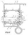
- Figure 1 schematically represents a section of a jamb 1 with a hinge 2 and a fixing element 3 according to the invention.
- the jamb 1 is in this case composed of two partial jambs 4 which can be made of aluminium or another material.
- the two partial jambs are provided with two grooves 9 on the opposite walls 8, which grooves face one another.
- grooves 9 are confined by two standing edges 10.
- edges 10 in particular the edges extending between the insulating jambs 7, can be made as a roll-in tooth 11 extending in the longitudinal direction of the jamb 1 which, while the jamb 1 is being put together, is externally upset, such that each insulation jamb 7 is firmly held in the groove 9 concerned.
- the insulating jambs 7 are provided with a cross passage 12 formed of two circular bore holes 13 having equal diameters.
- the bore holes 13 can be provided for example right along the outer jamb 6, i.e. as close as possible to the latter.
- a fixing element 3 is applied according to the invention which is formed of a pen 14 placed crosswise through the passage 12 in the insulating jambs 7 in an appropriate manner.
- This pen 14 is made of metal or another material.
- the length of the pen 14, measured according to the longitudinal direction of the axis, is at least as large as the thickness of the jamb 1 at the insulating jambs 7, such that a far end 15 of the pen 14 may possibly extend along one or both sides.
- the diameter of the pen 14 is preferably equal to the diameter of the bore holes 13 in the insulating jambs 7, such that the pen 14 fits exactly in the formed passage 12 in the insulating jambs 7.
- This threaded hole 16 extends as of the crosscut end 17 of the pen into the outer wall 18 of the pen 14. This continuous threaded hole 16 is situated at a certain angle A in relation to the axis x-x' of the pen 14.
- a locking screw 19 which has been screwed in the threaded hole 16 and which, when screwed down, makes contact with the jamb 1 with one of its free ends 20, preferably with the inner jamb 5 or the outer jamb 6.
- the locking screw 19 has a screw head 21 and a tip 22, whereby the screw head 21 preferably has the same diameter as the screw thread part 23 and is provided for example with a socket hole 24, and whereby the length of the locking screw 19 has been selected such that the head 21, when locked, is entirely concealed in the threaded hole 16 of the locking screw 19.
- the tip 22 of the locking screw 19 is provided with sharp cutting edges 25, which are formed for example by a conical opening 26 in this tip 22.
- the position and direction of the threaded hole 16 of the locking screw 19 are preferably selected such that, when screwing down the locking screw 19, the locking screw 19 is pressed behind one of the roll-in teeth 11 of the insulating jamb 7.
- the openings 13 are bored through the insulating jambs 7 so as to form a passage 12 for the pen 14.
- the pen 14 is pushed in this passage 12 and may either or not already have been connected to the hinge 2.
- the hinge 2 is welded directly to the pen 14 by means of a supporting plate 27.
- the locking screw 19 is screwed down in the threaded hole 16 of the pen 14.
- the locking screw 19 will cut with its cutting edge 25 at the tip 22 precisely alongside or even somewhat inside the roll-in tooth 11 of the wall 8 of the partial jamb 4.
- the cutting tip 22 of the locking screw 19 will thus cling to a wall 8 of a partial jamb 4.
- the pen 14 is also entirely clamped and fixed in the longitudinal direction, since the locking screw 19 is situated behind the roll-in tooth 11 in one direction and is stuck in the other direction thanks to its cutting tip 22.
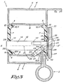
- Figure 2 represents a section of an alternative embodiment whereby the threaded hole of the locking screw 19 is provided at the far end of the pen 29 situated closest to the hinge 2.
- the locking screw 19 will clasp in a similar manner behind the roll-in tooth 11 of the other insulating jamb 7.
- This embodiment is advantageous in that the pen 14 can also be provided in a mounted door or window, since the pen 14 is inserted via the side of the hinge 2.
- the threaded hole 16 partly extends through the supporting plate 27 of the hinge 2.
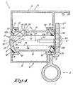
- Figure 3 represents a section of an alternative embodiment whereby the pen 14 is not fixed directly to the supporting plate 27 of the hinge 2.
- the far end of the pen 14 is in this case provided with a fastening plate 30, for example in the shape of a collar, having a larger diameter than the diameter of the pen.
- the pen 14 is hereby situated in the passage 12 of the insulating jambs 7 and is pulled tightly against the inner wall 31 of the jamb 1 by means of a similar construction with a locking screw 19, as in figure 2 , by screwing down said locking screw 19.
- the hinge 2 is screwed down on the fastening plate 30 of the pen 14 by means of the supporting plate 27.
- the pen 14 is provided with an additional threaded hole 32 extending in the longitudinal direction of the pen 14, and the hinge 2 is fixed by means of a screw 33 extending through an opening 34 in the hinge into the threaded hole 32.
- the threaded hole 32 of the fixing screw 33 is provided eccentrically in relation to the pen 14. In this way, the stability and strength of the connection between the hinge 2 and the jamb 1 are improved.
- the threaded hole 16 of the locking screw 19 is preferably provided at the crosscut end 17 of the hinge 2, which is advantageous in that the pen 14 can be put in place afterwards.
- the threaded hole 16 of the locking screw 19 in this case extends through the threaded hole 32 of the screw 33 in order to fix the hinge 2, and the length of the locking screw 19 is short enough for the screw head 21 of the locking screw 19 to leave the threaded hole 32 of the screw 33 free in order to fix the hinge 2.
- Figure 5 shows an alternative embodiment whereby the locking screw 19 meshes in a wall 8 of the inner jamb 5 instead of in a wall 8 of the outer jamb 6.
- This fastening may possibly be combined with a fastening by means of an additional locking screw cutting in the outer jamb.
- the grooves 9 for fixing the insulating jambs 7 are not formed by protruding edges, but rather by recessed parts in the partial jambs 4, such that no roll-in teeth 11 are present in this case.
- the locking screw 19 must not necessarily mesh behind a roll-in tooth 11. It is sufficient if the locking screw 19 cuts in one of the partial jambs 4 in order to obtain a rigid fastening.
- the inner jamb 5 and outer jamb 6 may be connected by one or several insulating jambs 7.
- a hinge 2 will be usually fixed in the jamb 1 by means of two or more pins 14 in practice, irrespective of the weight of the window or door for which the hinge 2 will be used.
Landscapes
- Engineering & Computer Science (AREA)
- Mechanical Engineering (AREA)
- Hinges (AREA)
- Wing Frames And Configurations (AREA)
- Connection Of Plates (AREA)
Claims (10)
- Elément de fixation (3) comprenant une vis de blocage pour fixer une charnière (2) à une huisserie (1) d'un encadrement de porte ou de fenêtre ou analogue, dans lequel l'élément de fixation (3) est réalisé sous la forme d'une plume (14) à laquelle est fixée ou peut être fixée la charnière (2), et est bloqué par rapport à cette huisserie (1) par le fait que la vis de blocage (19) fait saillie dans un trou de passage dans la plume (14) caractérisé en ce que le trou de passage (16) est un trou taraudé continu, et en ce que l'élément de fixation (3) peut être prévu en direction transversale à travers un passage (12) pratiqué dans l'huisserie, ledit élément de fixation (3) étant bloqué par rapport à cette huisserie (1) au moyen de ladite vis de blocage (19) qui est vissée dans le trou de passage (16) qui s'étend à travers la plume (14) en formant un angle comme celui d'une coupe transversale terminale (17) de la plume (14) par rapport à l'axe de la plume, jusqu'à la paroi externe (18) de la plume (14), la vis de blocage (19) pour fixer la charnière (2) étant vissée jusqu'à ce que son extrémité libre (20) entre en contact avec l'huisserie (1) en question.
- Élément de fixation (3) pour fixer une charnière (2) à une huisserie (1) selon la revendication 1, caractérisé en ce que l'huisserie (1) se compose de deux huisseries partielles (4) qui sont reliées l'une à l'autre au moyen d'une ou de plusieurs huisseries isolantes (7), et en ce que le passage (12) à travers lequel passe la plume (14) s'étend à travers une ou plusieurs huisseries isolantes (7), et en ce que la vis de blocage (19), lorsqu'elle est vissée, entre en contact avec une huisserie partielle (4) avec une extrémité libre (20).
- Élément de fixation (3) selon la revendication 2, caractérisé en ce qu'une ou plusieurs huisseries isolantes (7) sont maintenues dans une ou plusieurs rainures (9) des huisseries partielles (4), au moins une desdites rainures (9) étant confinée par une dent de roulement (11) s'étendant dans la direction longitudinale de l'huisserie (1), l'angle et la position du trou taraudé (16) étant tels que, lorsqu'on visse la vis de blocage (19), ladite vis de blocage (19) va s'accrocher derrière une dent de roulement (11) de l'huisserie partielle (4).
- Élément de fixation (3) selon l'une quelconque des revendications précédentes, caractérisé en ce que la vis de blocage (19) est une vis creuse dont la longueur a été sélectionnée de telle sorte que la tête (21) avec le trou de douille (24), lorsque la vis de blocage (19) est bloquée, est entièrement cachée dans le trou taraudé (16).
- Élément de fixation (3) selon l'une quelconque des revendications précédentes, caractérisé en ce que la vis de blocage (19) possède des arêtes vives (25) à l'extrémité (22), qui pénètrent par coupure dans la paroi d'une huisserie partielle (4), pendant le vissage de la vis de blocage (19).
- Élément de fixation (3) selon la revendication 2, caractérisé en ce que les arêtes vives (25) prennent la forme d'une ouverture conique (26) dans l'extrémité (22) de la vis de blocage (19).
- Élément de fixation (3) selon l'une quelconque des revendications précédentes, caractérisé en ce que la plume (14) est munie d'une plaque de fixation (30) à une extrémité éloignée, dans le diamètre est supérieur au diamètre de la plume (14) et contre laquelle est fixée la charnière (2) au moyen d'une vis (33) s'étendant à travers une ouverture (34) dans la charnière (2) pour pénétrer dans un trou taraudé (32) s'étendant dans la direction longitudinale de la plume (14).
- Élément de fixation (3) selon la revendication 7, caractérisé en ce que le trou taraudé (32) de la vis de fixation (33) est prévu en position excentrique par rapport à la plume.
- Élément de fixation (3) selon l'une quelconque des revendications précédentes, caractérisé en ce que le trou taraudé (16) pour la vis de blocage (19) s'étend à travers la plaque de fixation (30) et à travers le trou taraudé (32) pour fixer la plaque de fixation (30).
- Élément de fixation (3) selon l'une quelconque des revendications précédentes, caractérisé en ce que le trou taraudé (16) de la vis de blocage (19) est prévu à la coupe transversale terminale de la charnière (2).
Priority Applications (1)
| Application Number | Priority Date | Filing Date | Title |
|---|---|---|---|
| PL08075548T PL2009206T3 (pl) | 2007-06-26 | 2008-06-12 | Element mocujący przeznaczony do mocowania zawiasu do ościeżnicy drzwi, ościeżnicy okiennej lub podobnego elementu |
Applications Claiming Priority (1)
| Application Number | Priority Date | Filing Date | Title |
|---|---|---|---|
| BE2007/0317A BE1017661A3 (nl) | 2007-06-26 | 2007-06-26 | Bevestigingselement voor het bevestigen van een scharnier op een profiel van een kader van een deur of een raam of dergelijke. |
Publications (2)
| Publication Number | Publication Date |
|---|---|
| EP2009206A1 EP2009206A1 (fr) | 2008-12-31 |
| EP2009206B1 true EP2009206B1 (fr) | 2010-01-13 |
Family
ID=39015857
Family Applications (1)
| Application Number | Title | Priority Date | Filing Date |
|---|---|---|---|
| EP08075548A Not-in-force EP2009206B1 (fr) | 2007-06-26 | 2008-06-12 | Élément de fixation pour fixer une charnière sur le montant d'une porte ou cadre de fenêtre ou similaire |
Country Status (7)
| Country | Link |
|---|---|
| EP (1) | EP2009206B1 (fr) |
| AT (1) | ATE455223T1 (fr) |
| BE (1) | BE1017661A3 (fr) |
| DE (1) | DE602008000534D1 (fr) |
| ES (1) | ES2337847T3 (fr) |
| PL (1) | PL2009206T3 (fr) |
| PT (1) | PT2009206E (fr) |
Families Citing this family (2)
| Publication number | Priority date | Publication date | Assignee | Title |
|---|---|---|---|---|
| DE102009044020B3 (de) * | 2009-09-16 | 2011-04-28 | Dr. Hahn Gmbh & Co. Kg | Montageverfahren für ein Band zur scharniergelenkigen Befestigung eines Flügels, einer Tür, eines Fensters oder dergleichen, Band sowie Montagesystem |
| DE102011052313B3 (de) * | 2011-08-01 | 2012-03-01 | Simonswerk, Gesellschaft mit beschränkter Haftung | Trägerplatte zur Befestigung eines Türbandes an einem Hohlkammerprofil |
Family Cites Families (1)
| Publication number | Priority date | Publication date | Assignee | Title |
|---|---|---|---|---|
| DE1559983A1 (de) * | 1964-06-25 | 1969-12-18 | Schuermann & Co Heinz | Band,insbesondere fuer Metalltueren od.dgl. |
-
2007
- 2007-06-26 BE BE2007/0317A patent/BE1017661A3/nl not_active IP Right Cessation
-
2008
- 2008-06-12 EP EP08075548A patent/EP2009206B1/fr not_active Not-in-force
- 2008-06-12 PT PT08075548T patent/PT2009206E/pt unknown
- 2008-06-12 PL PL08075548T patent/PL2009206T3/pl unknown
- 2008-06-12 AT AT08075548T patent/ATE455223T1/de active
- 2008-06-12 ES ES08075548T patent/ES2337847T3/es active Active
- 2008-06-12 DE DE602008000534T patent/DE602008000534D1/de active Active
Also Published As
| Publication number | Publication date |
|---|---|
| BE1017661A3 (nl) | 2009-03-03 |
| ATE455223T1 (de) | 2010-01-15 |
| PL2009206T3 (pl) | 2010-06-30 |
| DE602008000534D1 (de) | 2010-03-04 |
| ES2337847T3 (es) | 2010-04-29 |
| EP2009206A1 (fr) | 2008-12-31 |
| PT2009206E (pt) | 2010-03-19 |
Similar Documents
| Publication | Publication Date | Title |
|---|---|---|
| JP2008008141A (ja) | 扉枠または窓枠に補助部材を取り付ける方法 | |
| DE19804801C1 (de) | Befestigung von Endkappen an Gehäusen, die aus Profilen bestehen | |
| DE8601106U1 (de) | Einstellbare Befestigungsvorrichtung zum Zusammenfügen von zwei Bauteilen | |
| EP2009206B1 (fr) | Élément de fixation pour fixer une charnière sur le montant d'une porte ou cadre de fenêtre ou similaire | |
| EP1332264B1 (fr) | Element de vis pour fixer un element de ferrures sur un profile creux pourvu d'une partie profilee saillante | |
| EP2093362B1 (fr) | Procédé et système de fixation pour une charnière ou autre ferrure sur les profils pour fenêtres et portes | |
| EP3187671A1 (fr) | Dispositif de verrouillage en tant que sécurité anti-effraction pour par exemple des fenêtres et des portes | |
| PL204765B1 (pl) | Tuleja do mocowania części okucia na profilu skrzynkowym | |
| EP2744960B1 (fr) | Partie de support de fenêtre, de porte ou analogues | |
| WO2006014139A1 (fr) | Charniere | |
| DE4431278A1 (de) | Beschlagelementesatz für Fenster, Türen o. dgl. | |
| US10538917B2 (en) | Shower enclosure header | |
| CN101103169A (zh) | 用于固定配件的安装螺栓 | |
| GB2488002A (en) | A back plate with at least one fixing sleeve | |
| EP0234784A2 (fr) | Gâche pour portes ou choses similaires | |
| AU2007201098B2 (en) | Window security system | |
| WO1999004125A1 (fr) | Partie penture a placer sur des huisseries en bois ou en metal pour fenetres ou portes | |
| EP2171191A1 (fr) | Élément de remplissage | |
| CZ185497A3 (cs) | Profilový prvek pro konstrukce dveřních rámů, okenních rámů a fasádní konstrukce | |
| KR200320190Y1 (ko) | 창틀의 모서리 연결구 | |
| CN116324107A (zh) | 用于安装到门或窗的框架或翼扇的空心型材上的伸缩式装置 | |
| SK174099A3 (en) | HOLDING DEVICE FOR THE FIXING PINS OF A WINDOW, DOOR OR FURNITUREì (54) HINGE | |
| DE19837024A1 (de) | System zum Befestigen von Verankerungsteilen an der Rückseite von Fassadenplatten | |
| DE202007003325U1 (de) | Beschlaganordnung und Montagerahmen | |
| KR200347366Y1 (ko) | 일체형 앵커 볼트 |
Legal Events
| Date | Code | Title | Description |
|---|---|---|---|
| PUAI | Public reference made under article 153(3) epc to a published international application that has entered the european phase |
Free format text: ORIGINAL CODE: 0009012 |
|
| AK | Designated contracting states |
Kind code of ref document: A1 Designated state(s): AT BE BG CH CY CZ DE DK EE ES FI FR GB GR HR HU IE IS IT LI LT LU LV MC MT NL NO PL PT RO SE SI SK TR |
|
| AX | Request for extension of the european patent |
Extension state: AL BA MK RS |
|
| 17P | Request for examination filed |
Effective date: 20081126 |
|
| GRAP | Despatch of communication of intention to grant a patent |
Free format text: ORIGINAL CODE: EPIDOSNIGR1 |
|
| AKX | Designation fees paid |
Designated state(s): AT BE BG CH CY CZ DE DK EE ES FI FR GB GR HR HU IE IS IT LI LT LU LV MC MT NL NO PL PT RO SE SI SK TR |
|
| GRAS | Grant fee paid |
Free format text: ORIGINAL CODE: EPIDOSNIGR3 |
|
| GRAA | (expected) grant |
Free format text: ORIGINAL CODE: 0009210 |
|
| AK | Designated contracting states |
Kind code of ref document: B1 Designated state(s): AT BE BG CH CY CZ DE DK EE ES FI FR GB GR HR HU IE IS IT LI LT LU LV MC MT NL NO PL PT RO SE SI SK TR |
|
| REG | Reference to a national code |
Ref country code: GB Ref legal event code: FG4D |
|
| REG | Reference to a national code |
Ref country code: CH Ref legal event code: EP |
|
| REG | Reference to a national code |
Ref country code: IE Ref legal event code: FG4D |
|
| REF | Corresponds to: |
Ref document number: 602008000534 Country of ref document: DE Date of ref document: 20100304 Kind code of ref document: P |
|
| REG | Reference to a national code |
Ref country code: PT Ref legal event code: SC4A Free format text: AVAILABILITY OF NATIONAL TRANSLATION Effective date: 20100309 |
|
| REG | Reference to a national code |
Ref country code: ES Ref legal event code: FG2A Ref document number: 2337847 Country of ref document: ES Kind code of ref document: T3 |
|
| LTIE | Lt: invalidation of european patent or patent extension |
Effective date: 20100113 |
|
| PG25 | Lapsed in a contracting state [announced via postgrant information from national office to epo] |
Ref country code: HR Free format text: LAPSE BECAUSE OF FAILURE TO SUBMIT A TRANSLATION OF THE DESCRIPTION OR TO PAY THE FEE WITHIN THE PRESCRIBED TIME-LIMIT Effective date: 20100113 Ref country code: LT Free format text: LAPSE BECAUSE OF FAILURE TO SUBMIT A TRANSLATION OF THE DESCRIPTION OR TO PAY THE FEE WITHIN THE PRESCRIBED TIME-LIMIT Effective date: 20100113 Ref country code: NO Free format text: LAPSE BECAUSE OF FAILURE TO SUBMIT A TRANSLATION OF THE DESCRIPTION OR TO PAY THE FEE WITHIN THE PRESCRIBED TIME-LIMIT Effective date: 20100413 Ref country code: IS Free format text: LAPSE BECAUSE OF FAILURE TO SUBMIT A TRANSLATION OF THE DESCRIPTION OR TO PAY THE FEE WITHIN THE PRESCRIBED TIME-LIMIT Effective date: 20100513 |
|
| PG25 | Lapsed in a contracting state [announced via postgrant information from national office to epo] |
Ref country code: FI Free format text: LAPSE BECAUSE OF FAILURE TO SUBMIT A TRANSLATION OF THE DESCRIPTION OR TO PAY THE FEE WITHIN THE PRESCRIBED TIME-LIMIT Effective date: 20100113 Ref country code: LV Free format text: LAPSE BECAUSE OF FAILURE TO SUBMIT A TRANSLATION OF THE DESCRIPTION OR TO PAY THE FEE WITHIN THE PRESCRIBED TIME-LIMIT Effective date: 20100113 Ref country code: SI Free format text: LAPSE BECAUSE OF FAILURE TO SUBMIT A TRANSLATION OF THE DESCRIPTION OR TO PAY THE FEE WITHIN THE PRESCRIBED TIME-LIMIT Effective date: 20100113 |
|
| PG25 | Lapsed in a contracting state [announced via postgrant information from national office to epo] |
Ref country code: SE Free format text: LAPSE BECAUSE OF FAILURE TO SUBMIT A TRANSLATION OF THE DESCRIPTION OR TO PAY THE FEE WITHIN THE PRESCRIBED TIME-LIMIT Effective date: 20100113 Ref country code: RO Free format text: LAPSE BECAUSE OF FAILURE TO SUBMIT A TRANSLATION OF THE DESCRIPTION OR TO PAY THE FEE WITHIN THE PRESCRIBED TIME-LIMIT Effective date: 20100113 Ref country code: GR Free format text: LAPSE BECAUSE OF FAILURE TO SUBMIT A TRANSLATION OF THE DESCRIPTION OR TO PAY THE FEE WITHIN THE PRESCRIBED TIME-LIMIT Effective date: 20100414 Ref country code: EE Free format text: LAPSE BECAUSE OF FAILURE TO SUBMIT A TRANSLATION OF THE DESCRIPTION OR TO PAY THE FEE WITHIN THE PRESCRIBED TIME-LIMIT Effective date: 20100113 Ref country code: CY Free format text: LAPSE BECAUSE OF FAILURE TO SUBMIT A TRANSLATION OF THE DESCRIPTION OR TO PAY THE FEE WITHIN THE PRESCRIBED TIME-LIMIT Effective date: 20100113 |
|
| PLBE | No opposition filed within time limit |
Free format text: ORIGINAL CODE: 0009261 |
|
| STAA | Information on the status of an ep patent application or granted ep patent |
Free format text: STATUS: NO OPPOSITION FILED WITHIN TIME LIMIT |
|
| PG25 | Lapsed in a contracting state [announced via postgrant information from national office to epo] |
Ref country code: SK Free format text: LAPSE BECAUSE OF FAILURE TO SUBMIT A TRANSLATION OF THE DESCRIPTION OR TO PAY THE FEE WITHIN THE PRESCRIBED TIME-LIMIT Effective date: 20100113 Ref country code: CZ Free format text: LAPSE BECAUSE OF FAILURE TO SUBMIT A TRANSLATION OF THE DESCRIPTION OR TO PAY THE FEE WITHIN THE PRESCRIBED TIME-LIMIT Effective date: 20100113 Ref country code: BG Free format text: LAPSE BECAUSE OF FAILURE TO SUBMIT A TRANSLATION OF THE DESCRIPTION OR TO PAY THE FEE WITHIN THE PRESCRIBED TIME-LIMIT Effective date: 20100413 |
|
| 26N | No opposition filed |
Effective date: 20101014 |
|
| PG25 | Lapsed in a contracting state [announced via postgrant information from national office to epo] |
Ref country code: MC Free format text: LAPSE BECAUSE OF NON-PAYMENT OF DUE FEES Effective date: 20100630 Ref country code: DK Free format text: LAPSE BECAUSE OF FAILURE TO SUBMIT A TRANSLATION OF THE DESCRIPTION OR TO PAY THE FEE WITHIN THE PRESCRIBED TIME-LIMIT Effective date: 20100113 |
|
| PG25 | Lapsed in a contracting state [announced via postgrant information from national office to epo] |
Ref country code: IE Free format text: LAPSE BECAUSE OF NON-PAYMENT OF DUE FEES Effective date: 20100612 Ref country code: MT Free format text: LAPSE BECAUSE OF FAILURE TO SUBMIT A TRANSLATION OF THE DESCRIPTION OR TO PAY THE FEE WITHIN THE PRESCRIBED TIME-LIMIT Effective date: 20100113 |
|
| PG25 | Lapsed in a contracting state [announced via postgrant information from national office to epo] |
Ref country code: HU Free format text: LAPSE BECAUSE OF FAILURE TO SUBMIT A TRANSLATION OF THE DESCRIPTION OR TO PAY THE FEE WITHIN THE PRESCRIBED TIME-LIMIT Effective date: 20100714 Ref country code: LU Free format text: LAPSE BECAUSE OF NON-PAYMENT OF DUE FEES Effective date: 20100612 |
|
| PG25 | Lapsed in a contracting state [announced via postgrant information from national office to epo] |
Ref country code: TR Free format text: LAPSE BECAUSE OF FAILURE TO SUBMIT A TRANSLATION OF THE DESCRIPTION OR TO PAY THE FEE WITHIN THE PRESCRIBED TIME-LIMIT Effective date: 20100113 |
|
| REG | Reference to a national code |
Ref country code: CH Ref legal event code: PL |
|
| REG | Reference to a national code |
Ref country code: CH Ref legal event code: PL |
|
| PG25 | Lapsed in a contracting state [announced via postgrant information from national office to epo] |
Ref country code: CH Free format text: LAPSE BECAUSE OF NON-PAYMENT OF DUE FEES Effective date: 20120630 Ref country code: LI Free format text: LAPSE BECAUSE OF NON-PAYMENT OF DUE FEES Effective date: 20120630 |
|
| REG | Reference to a national code |
Ref country code: FR Ref legal event code: PLFP Year of fee payment: 8 |
|
| PGFP | Annual fee paid to national office [announced via postgrant information from national office to epo] |
Ref country code: NL Payment date: 20150323 Year of fee payment: 8 Ref country code: PT Payment date: 20150326 Year of fee payment: 8 |
|
| PGFP | Annual fee paid to national office [announced via postgrant information from national office to epo] |
Ref country code: FR Payment date: 20150324 Year of fee payment: 8 |
|
| PGFP | Annual fee paid to national office [announced via postgrant information from national office to epo] |
Ref country code: BE Payment date: 20150306 Year of fee payment: 8 |
|
| PGFP | Annual fee paid to national office [announced via postgrant information from national office to epo] |
Ref country code: DE Payment date: 20150317 Year of fee payment: 8 Ref country code: GB Payment date: 20150429 Year of fee payment: 8 |
|
| PGFP | Annual fee paid to national office [announced via postgrant information from national office to epo] |
Ref country code: AT Payment date: 20150317 Year of fee payment: 8 Ref country code: IT Payment date: 20150526 Year of fee payment: 8 Ref country code: PL Payment date: 20150609 Year of fee payment: 8 |
|
| PGFP | Annual fee paid to national office [announced via postgrant information from national office to epo] |
Ref country code: ES Payment date: 20150730 Year of fee payment: 8 |
|
| PG25 | Lapsed in a contracting state [announced via postgrant information from national office to epo] |
Ref country code: BE Free format text: LAPSE BECAUSE OF NON-PAYMENT OF DUE FEES Effective date: 20160630 |
|
| REG | Reference to a national code |
Ref country code: DE Ref legal event code: R119 Ref document number: 602008000534 Country of ref document: DE |
|
| REG | Reference to a national code |
Ref country code: NL Ref legal event code: MM Effective date: 20160701 |
|
| REG | Reference to a national code |
Ref country code: AT Ref legal event code: MM01 Ref document number: 455223 Country of ref document: AT Kind code of ref document: T Effective date: 20160612 |
|
| PG25 | Lapsed in a contracting state [announced via postgrant information from national office to epo] |
Ref country code: PT Free format text: LAPSE BECAUSE OF NON-PAYMENT OF DUE FEES Effective date: 20161212 |
|
| GBPC | Gb: european patent ceased through non-payment of renewal fee |
Effective date: 20160612 |
|
| REG | Reference to a national code |
Ref country code: FR Ref legal event code: ST Effective date: 20170228 |
|
| PG25 | Lapsed in a contracting state [announced via postgrant information from national office to epo] |
Ref country code: FR Free format text: LAPSE BECAUSE OF NON-PAYMENT OF DUE FEES Effective date: 20160630 Ref country code: DE Free format text: LAPSE BECAUSE OF NON-PAYMENT OF DUE FEES Effective date: 20170103 |
|
| PG25 | Lapsed in a contracting state [announced via postgrant information from national office to epo] |
Ref country code: AT Free format text: LAPSE BECAUSE OF NON-PAYMENT OF DUE FEES Effective date: 20160612 Ref country code: GB Free format text: LAPSE BECAUSE OF NON-PAYMENT OF DUE FEES Effective date: 20160612 Ref country code: NL Free format text: LAPSE BECAUSE OF NON-PAYMENT OF DUE FEES Effective date: 20160701 |
|
| PG25 | Lapsed in a contracting state [announced via postgrant information from national office to epo] |
Ref country code: IT Free format text: LAPSE BECAUSE OF NON-PAYMENT OF DUE FEES Effective date: 20160612 |
|
| PG25 | Lapsed in a contracting state [announced via postgrant information from national office to epo] |
Ref country code: PL Free format text: LAPSE BECAUSE OF NON-PAYMENT OF DUE FEES Effective date: 20160612 |
|
| PG25 | Lapsed in a contracting state [announced via postgrant information from national office to epo] |
Ref country code: ES Free format text: LAPSE BECAUSE OF NON-PAYMENT OF DUE FEES Effective date: 20160613 |
|
| REG | Reference to a national code |
Ref country code: ES Ref legal event code: FD2A Effective date: 20180626 |