EP2008877A1 - Filet à bagage doux - Google Patents
Filet à bagage doux Download PDFInfo
- Publication number
- EP2008877A1 EP2008877A1 EP07111456A EP07111456A EP2008877A1 EP 2008877 A1 EP2008877 A1 EP 2008877A1 EP 07111456 A EP07111456 A EP 07111456A EP 07111456 A EP07111456 A EP 07111456A EP 2008877 A1 EP2008877 A1 EP 2008877A1
- Authority
- EP
- European Patent Office
- Prior art keywords
- supporting bar
- cargo restraint
- restraint according
- elongate
- sections
- Prior art date
- Legal status (The legal status is an assumption and is not a legal conclusion. Google has not performed a legal analysis and makes no representation as to the accuracy of the status listed.)
- Withdrawn
Links
Images


Classifications
-
- B—PERFORMING OPERATIONS; TRANSPORTING
- B60—VEHICLES IN GENERAL
- B60R—VEHICLES, VEHICLE FITTINGS, OR VEHICLE PARTS, NOT OTHERWISE PROVIDED FOR
- B60R21/00—Arrangements or fittings on vehicles for protecting or preventing injuries to occupants or pedestrians in case of accidents or other traffic risks
- B60R21/02—Occupant safety arrangements or fittings, e.g. crash pads
- B60R21/06—Safety nets, transparent sheets, curtains, or the like, e.g. between occupants and glass
Definitions
- the present invention relates generally to vehicle safety devices, and more particularly, to a frame and attachment construction for use with a cargo restraint that protects persons in the passenger compartment from objects thrust from the storage compartment in a utility vehicle during a sudden deceleration.
- EP1128992 shows a known arrangement that utilizes a generally rectangular safety web suspended transversely between the passenger compartment and the storage compartment.
- the web arrangement attaches to the vehicle at its upper and lower side edges.
- the upper and lower side edge of the web contains rod-like frames, which are each provided with a hinge to allow folding of the safety web when not in use.
- This known safety web arrangement is provided with hinges in order to facilitate handling and stowing of the safety web.
- the safety web When not in use, the safety web can be wound onto one of the two struts and it then occupies correspondingly little space.
- the relatively long struts and the locking/unlocking of the hinges present a problem in handling the web.
- One object of the present invention to provide an improved cargo restraint construction that adequately addresses safety concerns in a utility vehicle and which, when not in use, can easily be folded and stored in the vehicle.
- the invention relates to a cargo restraint arranged between a passenger compartment and an article storage compartment in a utility vehicle interior defined by a vehicle ceiling, opposed side walls and a load floor.
- the cargo restraint may comprise a web body including an upper marginal edge extending substantially between the vehicle side walls proximate to the vehicle ceiling, and a lower marginal edge extending substantially between the vehicle side walls proximate to a passenger seat back.
- the web body may extend downwards into a position at least partially overlapping an upper portion of the seat back, into a position adjacent the upper surface of the load floor, or into any intermediate position, depending on the size of the web body and the desired extension thereof.
- a first elongate supporting bar may be attached to the upper marginal edge of the web body, the first supporting bar having its opposed ends connected to an upper section of the storage compartment to suspend the web body there from.
- the first elongate supporting bar may comprise at least two sections, said sections of the first elongate supporting bar being movable relative to each other into an operative mounting position that defines an effective length of the first elongate supporting bar, said sections of the bar being connected with a connector which secures the sections of the first elongate supporting bar in the operative mounting position. In its mounted position, the first elongate supporting bar makes up an upper supporting bar.
- the cargo restraint further comprises at least a second and a third elongated supporting bar attached to the lower marginal edge of the web body, forming a lower supporting bar.
- the second and third elongated supporting bar may be located in a lower section of the storage compartment and are attached at a pair of opposed, outer ends.
- At least one pair of adjacent, facing end sections of the said second and third elongate supporting bars may be arranged separate from and movable relative to each other. The number of facing end sections is dependent on the number of sections making up the lower supporting bar.
- the number of sections in the first elongate supporting bar is equal to the number of elongated supporting bars attached to the lower marginal edge of the web body.
- the number of sections may be chosen depending on the desired length of the folded cargo restraint, and would preferably, but not necessarily be limited to two or three sections.
- the connector between each section of the first elongate supporting bar is a hinge having a hinge axis that subdivides the first elongate supporting bar into said sections and which permits shortening the effective length of the first elongate supporting bar by folding of the sections.
- the hinges for the respective first elongate supporting bar are arranged such that said sections of the first elongate supporting bar are of equal length.
- Each hinge of the first elongate supporting bar is aligned with each elongated supporting bar attached to the lower marginal edge of the web body so that, when the cargo restraint is mounted in the vehicle, the first elongate supporting bar is parallel to the second and third elongated supporting bars.
- the pivot axis of the at least one hinge for the first elongate supporting bar is at least approximately aligned with a line intersecting the longitudinal axes of the second and third elongated supporting bars when the cargo restraint is mounted in an operative position the vehicle.
- the at least one hinge for the first elongate supporting bar is lockable in at least a first position.
- the said first position corresponds to an operative position of the respective strut.
- the lockable position can be achieved by any suitable means, such as the frictional forces between adjacent surfaces or a spring loaded locking means.
- the first elongate supporting bar may be released from its locked position by applying sufficient force to overcome the friction between cooperating surfaces in the hinge. Alternatively it may be released by overcoming a spring loaded latch, which may be overcome by applying sufficient force or by releasing the latch using a lever or a push button.
- the at least one hinge for the first elongate supporting bar may also be releasably lockable in a folded form.
- the hinge may be provided with a
- the web body making up the main part of the cargo restraint may preferably, but not necessarily, comprise a net.
- the net may be made from any suitable spun fabric or plastic or reinforced plastic material.
- the web may comprise a sheet of fabric or plastic material
- the opposed ends of the first supporting bar are adapted to be engaged in receiving slots formed in the side walls of the upper section of the storage compartment.
- the ends of the first supporting bar are provided with attachment means allowing a user to hook the ends in place from one side of the vehicle, whereby the cooperating slots and attachment means are supported to absorb forces transmitted from the web body when objects come into contact with said web body.
- the opposed ends of the second and third elongated supporting bars are adapted to be engaged in receiving slots formed in the side walls of the lower section of the storage compartment.
- the opposed ends of the second and third elongated supporting bars may be provided with the same cooperating slots and attachment means as used for the first supporting bar, or merely rest in cooperating slots preventing forwards and upward displacement of the ends of the second and third elongated supporting bars. In the latter example, additional anchoring members may be used to hold the second and third bars in place.
- each said second and third elongated supporting bar may be secured to the vehicle adjacent the load floor intermediate the side walls.
- said second and third elongated supporting bars are secured to the vehicle at a fastening location intermediate the ends of the respective second and third supporting bar.
- each said second and third elongated supporting bar may include anchoring members at a predetermined distance from the opposite, outer ends of said bars.
- the anchoring members may be provided with snap-on connectors, or be attached using hooks or connectors cooperating with existing load hooks in the load floor.
- the cargo restraint may be arranged in a first alternative position proximate to a rear passenger seat back. This position is commonly used when at least a part of the rear passenger seat is in use, wherein the cargo restraint is used for reducing the loading on the seat back, for preventing objects from being thrown forward over the upper part of the rear seat back, and/or for restraining objects from being displaced forwards where at least a section of the rear passenger seat back has been folded to form an extended load floor.
- the restraint may also be arranged in a second alternative position proximate a front passenger seat back.
- This position is preferably, but not necessarily, used when at least a section of the rear passenger seat back is folded to form an extended load floor.
- the cargo restraint is used for reducing the loading on the front passenger and/or driver seat back, for preventing objects from being thrown forward over the upper part of the front passenger and/or driver seat back, and/or for restraining objects from being displaced forwards where the front passenger seat back has been folded to form an extended load floor next to the drivers seat.
- the cargo restraint may comprise a first fabric strip attached to the upper marginal edge of the web body, the first fabric strip being folded over to form a receiving sleeve retaining the first elongated supporting bar therein.
- the first fabric strip may enclose the at least one hinge or be provided with cut-outs to facilitate folding of the said hinge.
- a second fabric strip attached to the lower marginal edge of the web body, the second fabric strip being folded over to form a receiving sleeve retaining the second and third elongated supporting bars therein.
- the receiving sleeve retaining the second and third elongated supporting bars is preferably closed between the facing ends of said bars.
- the second and third supporting bars may be attached to their respective section of the retaining sleeve, to prevent the facing ends from coming into contact.
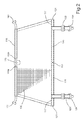
- Figure 1 shows a schematic cross-sectional view of a vehicle storage compartment 100 provided with a cargo restraint 101 according to one embodiment of the invention.
- the cargo restraint 101 is arranged between a passenger compartment (not shown) and the article storage compartment 100 in a utility vehicle interior defined by a vehicle ceiling 102, opposed side walls 103, 104 and a load floor 105.
- the cargo restraint 101 comprises a web body 106 including an upper marginal edge 107 extending substantially between the vehicle side walls 103, 104 proximate to the vehicle ceiling 102, and a lower marginal edge 108 extending substantially between the vehicle side walls 103, 104 proximate to a passenger seat back 109.
- a first elongate supporting bar 110 is attached to the upper marginal edge of the web body 106, which first supporting bar has hooks (not shown) at its opposed ends 111, 112 connected to cooperating slots 113, 114 adjacent the ceiling 102 in the upper section of the storage compartment, in order to suspend the web body 106 there from.
- the first elongate supporting bar 110 comprises two sections 110a, 110b, which sections are movable relative to each other by means of a hinge 115 into an operative mounting position that defines an effective length of the first elongate supporting bar 110.
- the hinge 115 connecting the two sections 110a, 110b of the bar is lockable in a first position corresponding to an operative position of the first elongate supporting bar 110 in the operative mounting position shown in Figure 1 , or releasable to allow said sections 110a, 110b of the first elongate supporting bar 110 to be folded and stowed.
- the cargo restraint 101 further comprises a second and a third elongated supporting bar 120, 130 attached to the lower marginal edge 108 of the web body 106.
- the second and third elongated supporting bar 120, 130 are located in a lower section of the storage compartment 100 and are attached at a pair of opposed, outer ends 121, 131. At least one pair of adjacent, facing end sections 122, 132 of the said second and third elongate supporting bars 120, 130 are arranged separate from and movable relative to each other.
- each said second and third elongated supporting bar 120, 130 is secured to the vehicle adjacent the load floor 105 intermediate the side walls 103, 104.
- said second and third elongated supporting bars 120, 130 are secured to the vehicle at a fastening location intermediate the ends of the respective second and third supporting bar, preferably adjacent a central section of the respective bar 120, 130.
- each said second and third elongated supporting bar includes anchoring members at a predetermined distance from the opposite, outer ends of said bars.
- the anchoring members comprise straps 123, 133 provided with snap-on connectors 124, 134 cooperating with mating connectors 125, 135 attached to the load floor 105.
- the connectors can be of the same type as used in seat belt attachments.
- the cargo restraint 101 comprises a first fabric strip 116 attached to the upper marginal edge 107 of the web body 106.
- the first fabric strip 116 is folded over to form a receiving sleeve retaining the first elongated supporting bar 110 therein.
- the first fabric strip 116 is provided with cut-outs to facilitate folding of the said hinge 115.
- a second fabric strip 117 is attached to the lower marginal edge 108 of the web body 106.
- the second fabric strip 117 is folded over to form a receiving sleeve retaining the second and third elongated supporting bars 120, 130 therein.
- the receiving sleeve retaining the second and third elongated supporting bars 120, 130 comprises a closed section 118 between the facing ends 122, 132 of said bars.
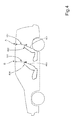
- Figure 2 shows a front view of the cargo restraint of Figure 1 in a substantially flat, vertical position, which it assumes when mounted in its operative position in the vehicle.
- the cargo restraint 101 comprises a web body 106 including a first elongate supporting bar 110 attached to the upper marginal edge of the web body 106.
- the first supporting bar has hooks at its opposed ends 111, 112.
- the first elongate supporting bar 110 comprises two sections 110a, 110b, which sections are locked in the position shown by means of a lockable hinge 115.
- the operative mounting position defines the effective length of the first elongate supporting bar 110.
- the hinge 115 connecting the two sections 110a, 110b of the bar is lockable in a first position corresponding to the said operative position, or releasable to allow said sections 110a, 110b of the first elongate supporting bar 110 to be folded and stowed.
- the cargo restraint 101 further comprises a second and a third elongated supporting bar 120, 130 attached to the lower marginal edge of the web body 106.
- the second and third elongated supporting bar 120, 130 are located in a lower section of the storage compartment 100 and are provided with a pair of opposed, outer ends 121, 131 arranged for holding the lower edge of the cargo restraint in position.
- a pair of adjacent, facing end sections 122, 132 of the said second and third elongate supporting bars 120, 130 are arranged separate from and movable relative to each other.
- the cargo restraint 101 comprises a first fabric strip 116 folded over to form a receiving sleeve retaining the first elongated supporting bar 110 therein.
- the first fabric strip 116 is provided with cut-outs to facilitate folding of the said hinge 115.
- a second fabric strip 117 is attached to the lower marginal edge 108 of the web body 106.
- the second fabric strip 117 is folded over to form a receiving sleeve retaining the second and third elongated supporting bars 120, 130 therein.
- the receiving sleeve retaining the second and third elongated supporting bars 120, 130 comprises a closed section 118 between the facing ends 122, 132 of said bars.
- the closed section 118 is achieved by a seam that closes off the folded sleeve, and which section allows the second and third elongated supporting bars 120, 130 to be folded relative to each other.
- the cooperating portions (not shown) making up the hinge 115 comprise facing surfaces in frictional contact.
- the facing surfaces are provided with a cooperating projection and notch arrangement.
- the hinge 115 can be provided with an actuator, such as a push-button, that is depressed to release the locking mechanism and allow relative movement of the two sections 110a, 110b of the said bar 110, either after an initial depression of the push button or while the push-button is kept depressed.
- an actuator such as a push-button
- the second and third elongated supporting bars 120, 130 will automatically unfold as the first elongated supporting bar 110 is unfolded and locked.
- the user will place the hooks at the respective outer ends 111, 112 of said bar 110 into the cooperating slots 113, 114 adjacent the ceiling 102 in the upper section of the storage compartment (see Figure 1 ), in order to suspend the web body 106 there from.
- the user will connect the straps 123, 133 and their snap-on connectors 124, 134 with the mating connectors 125, 135 attached to the load floor 105 (see Figure 1 ), in order to anchor the lower edge of the cargo restraint to the vehicle and stretch the web body 106.
- FIG 3 shows the cargo restraint of Figure 2 during folding.
- the mounting operation is simply reversed.
- the cargo restraint may be folded.
- the hinge 115 is released by applying sufficient force to overcome the frictional forces between the surfaces of the hinge portions, in order to allow relative movement of the two sections 110a, 110b of the said bar 110.
- the second and third elongated supporting bars 120, 130 will automatically fold as the first elongated supporting bar 110 is folded and locked. In this way, folding and unfolding of the entire cargo restraint can be achieved simply by manipulating the first elongated supporting bar 110 only.
- Figure 4 shows a schematic cross-section of a vehicle comprising two alternative positions for a cargo net 101 according to the invention.
- the figure only shows a schematic representation of the cargo restraint, which can be given a greater or smaller vertical extension depending on the desired function of the cargo restraint.
- the cargo restraint may be arranged in a first alternative position A proximate to a rear passenger seat back 401. This position is commonly used when the rear passenger seat 402 is in its upright position, wherein the cargo restraint 101 is used for reducing the loading on the seat back 401 and for preventing objects from being thrown forward over the upper part of the rear seat back.
- the cargo restraint can be used for restraining objects from being displaced forwards where at least a section of the rear passenger seat 402 has been folded to form an extended load floor.
- the cargo restraint 101 may also be arranged in a second alternative position B proximate a front passenger seat back 403.
- This position is preferably, but not necessarily, used when the front passenger seat 404 is in its upright position and the rear passenger seat 402 is folded to form an extended load floor.
- the second alternative position B can also be used when the front passenger seat 404 adjacent the driver's seat has been folded to form an extended load floor and/or at least a section of the rear passenger seat 402 is in its upright position.
- the cargo restraint 101 is used in position B for reducing the loading on the front passenger and/or driver seat back 403, for preventing objects from being thrown forward over the upper part of the front passenger and/or driver seat back, and/or for restraining objects from being displaced forwards where the front passenger seat back has been folded to form an extended load floor next to the drivers seat.
Landscapes
- Engineering & Computer Science (AREA)
- Mechanical Engineering (AREA)
- Vehicle Step Arrangements And Article Storage (AREA)
Priority Applications (3)
| Application Number | Priority Date | Filing Date | Title |
|---|---|---|---|
| EP07111456A EP2008877A1 (fr) | 2007-06-29 | 2007-06-29 | Filet à bagage doux |
| CNA2008101293752A CN101332798A (zh) | 2007-06-29 | 2008-06-26 | 货物限制网 |
| US12/163,160 US20090045652A1 (en) | 2007-06-29 | 2008-06-27 | Cargo net |
Applications Claiming Priority (1)
| Application Number | Priority Date | Filing Date | Title |
|---|---|---|---|
| EP07111456A EP2008877A1 (fr) | 2007-06-29 | 2007-06-29 | Filet à bagage doux |
Publications (1)
| Publication Number | Publication Date |
|---|---|
| EP2008877A1 true EP2008877A1 (fr) | 2008-12-31 |
Family
ID=38520981
Family Applications (1)
| Application Number | Title | Priority Date | Filing Date |
|---|---|---|---|
| EP07111456A Withdrawn EP2008877A1 (fr) | 2007-06-29 | 2007-06-29 | Filet à bagage doux |
Country Status (3)
| Country | Link |
|---|---|
| US (1) | US20090045652A1 (fr) |
| EP (1) | EP2008877A1 (fr) |
| CN (1) | CN101332798A (fr) |
Cited By (3)
| Publication number | Priority date | Publication date | Assignee | Title |
|---|---|---|---|---|
| EP2135780A1 (fr) | 2008-06-18 | 2009-12-23 | Centre d'etude et de recherche pour l'automobile (CERA) | Montage d'un dispositif de protection contre la projection de bagages d'un compartiment à bagages de véhicule automobile |
| EP2674333A1 (fr) * | 2012-06-11 | 2013-12-18 | Volvo Car Corporation | Diviseur de compartiment pliable pour véhicule |
| EP4223594A1 (fr) * | 2022-02-04 | 2023-08-09 | Klippan Safety AB | Filet de barrière |
Families Citing this family (10)
| Publication number | Priority date | Publication date | Assignee | Title |
|---|---|---|---|---|
| DE102011089444B4 (de) * | 2011-12-21 | 2019-07-04 | Bos Gmbh & Co. Kg | Schutzvorrichtung für einen Fahrzeuginnenraum |
| US9421932B2 (en) * | 2013-02-15 | 2016-08-23 | Doskocil Manufacturing Company, Inc. | Partition apparatus for use in a vehicle |
| US20160339846A1 (en) * | 2015-05-18 | 2016-11-24 | Ford Global Technologies, Llc | Integrated cargo cover |
| DE102016115667A1 (de) * | 2016-08-24 | 2018-03-01 | Dr. Ing. H.C. F. Porsche Aktiengesellschaft | Vorrichtung zur Befestigung eines Fangnetzes in einem Fahrzeug |
| USD835027S1 (en) * | 2016-12-16 | 2018-12-04 | Kia Motors Corporation | Luggage net for automobile |
| DE102017200962A1 (de) * | 2017-01-20 | 2018-07-26 | Ford Global Technologies, Llc | Frachtbarriere für ein Kraftfahrzeug |
| US10576869B2 (en) * | 2017-01-26 | 2020-03-03 | Ford Global Technologies, Llc | Self-retractable cargo net |
| US10787131B2 (en) * | 2018-03-13 | 2020-09-29 | Ford Global Technologies, Llc | Roof accessory interface |
| US20190359039A1 (en) * | 2018-05-24 | 2019-11-28 | Honda Motor Co., Ltd. | Barrier for a vehicle opening |
| US11453345B2 (en) | 2019-06-12 | 2022-09-27 | Ford Global Technologies, Llc | Vehicle multi-purpose brackets |
Citations (2)
| Publication number | Priority date | Publication date | Assignee | Title |
|---|---|---|---|---|
| DE19944003C1 (de) * | 1999-09-14 | 2001-03-22 | Baumeister & Ostler Gmbh Co | Faltbare Trenneinrichtung |
| DE20019037U1 (de) * | 2000-11-08 | 2002-03-28 | Butz Peter Verwaltung | Bahnförmige Rückhaltevorrichtung mit faltbarer Haltestange für den Innenraum von Kraftfahrzeugen |
Family Cites Families (3)
| Publication number | Priority date | Publication date | Assignee | Title |
|---|---|---|---|---|
| US1023094A (en) * | 1911-11-17 | 1912-04-09 | Palmer I E Co | Folding unitary screen. |
| US3016952A (en) * | 1959-01-21 | 1962-01-16 | Ronald D Shero | Automobile window screen |
| US6817644B2 (en) * | 1995-11-22 | 2004-11-16 | Exco Automotive Solutions, L.P. | Load retaining barrier net for motor vehicle |
-
2007
- 2007-06-29 EP EP07111456A patent/EP2008877A1/fr not_active Withdrawn
-
2008
- 2008-06-26 CN CNA2008101293752A patent/CN101332798A/zh active Pending
- 2008-06-27 US US12/163,160 patent/US20090045652A1/en not_active Abandoned
Patent Citations (2)
| Publication number | Priority date | Publication date | Assignee | Title |
|---|---|---|---|---|
| DE19944003C1 (de) * | 1999-09-14 | 2001-03-22 | Baumeister & Ostler Gmbh Co | Faltbare Trenneinrichtung |
| DE20019037U1 (de) * | 2000-11-08 | 2002-03-28 | Butz Peter Verwaltung | Bahnförmige Rückhaltevorrichtung mit faltbarer Haltestange für den Innenraum von Kraftfahrzeugen |
Cited By (4)
| Publication number | Priority date | Publication date | Assignee | Title |
|---|---|---|---|---|
| EP2135780A1 (fr) | 2008-06-18 | 2009-12-23 | Centre d'etude et de recherche pour l'automobile (CERA) | Montage d'un dispositif de protection contre la projection de bagages d'un compartiment à bagages de véhicule automobile |
| FR2932750A1 (fr) * | 2008-06-18 | 2009-12-25 | Cera | Dispositif de protection contre la projection de bagages d'un compartiment a bagages de vehicule automobile |
| EP2674333A1 (fr) * | 2012-06-11 | 2013-12-18 | Volvo Car Corporation | Diviseur de compartiment pliable pour véhicule |
| EP4223594A1 (fr) * | 2022-02-04 | 2023-08-09 | Klippan Safety AB | Filet de barrière |
Also Published As
| Publication number | Publication date |
|---|---|
| US20090045652A1 (en) | 2009-02-19 |
| CN101332798A (zh) | 2008-12-31 |
Similar Documents
| Publication | Publication Date | Title |
|---|---|---|
| EP2008877A1 (fr) | Filet à bagage doux | |
| US6394525B1 (en) | Vehicle seat | |
| JP4993786B2 (ja) | 蛇篭の展開 | |
| US5288122A (en) | Load restraining device | |
| US6073986A (en) | Easily handled movable vehicle seat assembly | |
| US6595567B1 (en) | Foldable separating device | |
| US8556324B1 (en) | Utility vehicle | |
| US6874840B2 (en) | Stow to floor seat assembly having a cantilevered seat cushion | |
| US5647611A (en) | Vehicle safety belt system | |
| US8235445B2 (en) | Vehicle seat on demand | |
| NO326799B1 (no) | Militaert motorkjoretoy for personelltransport | |
| CN206327269U (zh) | 用于机动车辆的可伸缩货物盖系统 | |
| JPH06340241A (ja) | 自動車のためのガスバッグ拘束装置 | |
| KR20050102352A (ko) | 자동차용 리어 시트백의 백보드 전개 구조 | |
| EP0515481B1 (fr) | Dispositif de retenue pour chargements | |
| CN107458314B (zh) | 行李箱地板遮盖装置和包含该遮盖装置的汽车行李箱 | |
| SE521184C2 (sv) | Lasthållande arrangemang | |
| EP3763562B1 (fr) | Système de partitionnement de siège de véhicule et véhicule comprenant un système de partitionnement de siège de véhicule | |
| JP4005341B2 (ja) | 車両用荷崩れ防止装置 | |
| US3751090A (en) | Vehicle fender | |
| WO2020211704A1 (fr) | Système de cage pliable pour véhicule | |
| KR100472149B1 (ko) | 시트백 강도보강용 시트벨트 취부구조 | |
| KR0160020B1 (ko) | 차량의 리어시트에 설치된 화물 차단 장치 | |
| KR200151719Y1 (ko) | 자동차용 뒤의자 | |
| JP4107939B2 (ja) | 車両用荷崩れ防止装置 |
Legal Events
| Date | Code | Title | Description |
|---|---|---|---|
| PUAI | Public reference made under article 153(3) epc to a published international application that has entered the european phase |
Free format text: ORIGINAL CODE: 0009012 |
|
| AK | Designated contracting states |
Kind code of ref document: A1 Designated state(s): AT BE BG CH CY CZ DE DK EE ES FI FR GB GR HU IE IS IT LI LT LU LV MC MT NL PL PT RO SE SI SK TR |
|
| AX | Request for extension of the european patent |
Extension state: AL BA HR MK RS |
|
| 17P | Request for examination filed |
Effective date: 20090610 |
|
| 17Q | First examination report despatched |
Effective date: 20090708 |
|
| AKX | Designation fees paid |
Designated state(s): DE GB SE |
|
| STAA | Information on the status of an ep patent application or granted ep patent |
Free format text: STATUS: THE APPLICATION IS DEEMED TO BE WITHDRAWN |
|
| 18D | Application deemed to be withdrawn |
Effective date: 20100220 |