EP2007947B1 - Dispositif de guidage pour torons - Google Patents
Dispositif de guidage pour torons Download PDFInfo
- Publication number
- EP2007947B1 EP2007947B1 EP06754767.9A EP06754767A EP2007947B1 EP 2007947 B1 EP2007947 B1 EP 2007947B1 EP 06754767 A EP06754767 A EP 06754767A EP 2007947 B1 EP2007947 B1 EP 2007947B1
- Authority
- EP
- European Patent Office
- Prior art keywords
- strand
- channel
- face
- faces
- curvature
- Prior art date
- Legal status (The legal status is an assumption and is not a legal conclusion. Google has not performed a legal analysis and makes no representation as to the accuracy of the status listed.)
- Active
Links
Images


Classifications
-
- F—MECHANICAL ENGINEERING; LIGHTING; HEATING; WEAPONS; BLASTING
- F16—ENGINEERING ELEMENTS AND UNITS; GENERAL MEASURES FOR PRODUCING AND MAINTAINING EFFECTIVE FUNCTIONING OF MACHINES OR INSTALLATIONS; THERMAL INSULATION IN GENERAL
- F16G—BELTS, CABLES, OR ROPES, PREDOMINANTLY USED FOR DRIVING PURPOSES; CHAINS; FITTINGS PREDOMINANTLY USED THEREFOR
- F16G13/00—Chains
- F16G13/12—Hauling- or hoisting-chains so called ornamental chains
- F16G13/16—Hauling- or hoisting-chains so called ornamental chains with arrangements for holding electric cables, hoses, or the like
-
- E—FIXED CONSTRUCTIONS
- E01—CONSTRUCTION OF ROADS, RAILWAYS, OR BRIDGES
- E01D—CONSTRUCTION OF BRIDGES, ELEVATED ROADWAYS OR VIADUCTS; ASSEMBLY OF BRIDGES
- E01D19/00—Structural or constructional details of bridges
- E01D19/14—Towers; Anchors ; Connection of cables to bridge parts; Saddle supports
-
- F—MECHANICAL ENGINEERING; LIGHTING; HEATING; WEAPONS; BLASTING
- F16—ENGINEERING ELEMENTS AND UNITS; GENERAL MEASURES FOR PRODUCING AND MAINTAINING EFFECTIVE FUNCTIONING OF MACHINES OR INSTALLATIONS; THERMAL INSULATION IN GENERAL
- F16G—BELTS, CABLES, OR ROPES, PREDOMINANTLY USED FOR DRIVING PURPOSES; CHAINS; FITTINGS PREDOMINANTLY USED THEREFOR
- F16G11/00—Means for fastening cables or ropes to one another or to other objects; Caps or sleeves for fixing on cables or ropes
- F16G11/02—Means for fastening cables or ropes to one another or to other objects; Caps or sleeves for fixing on cables or ropes with parts deformable to grip the cable or cables; Fastening means which engage a sleeve or the like fixed on the cable
Definitions
- the invention relates to a guide device for strands.
- the invention also relates to constructions comprising the above-mentioned strand guiding device.
- the invention applies more particularly, but not exclusively to the realization of guiding devices for cable strands which, consisting of a plurality of strands, are used in civil engineering.
- bridges and particularly bridges include cables that are used to, in particular, support elements of these structures and / or maintain them between them.
- Such cables are essentially stressed in traction between their opposite ends, but it is common practice to use guiding devices to hold them laterally and locally, so as to somehow deflect them from the direction in which they should be. 'to spread.
- the function of a guiding device of the aforementioned type is therefore to allow the lateral and local maintenance of a cable and the transfer of the load induced by this deviation to a support provided for this purpose.
- a guiding device of the aforementioned type is intended to be interposed between the support and the cable.
- such a guiding device is designed to allow individual lateral and local support of each strand of the cable.
- a guiding device comprises at least one guide surface for a cable strand and preferably a plurality of deflection surfaces each allowing the individual support of one of the strands of a cable.
- a guide device is constituted by a body, generally massive, in which is formed at least one curved channel, said channel, to be traversed by the strand.
- the body comprises at least as many channels as the cable to be guided comprises strands.
- the strands each consist of several son, usually but not limited to metal.
- the strands often have a cross section that fits in a circle, but this section can also be oval or some other shape.
- the channels each have a cross section of shape substantially complementary to that of the strand they must receive.
- each channel has a substantially circular cross section of a diameter greater than the circle in which the cross section of a strand fits.
- each channel of the body comprises a curved longitudinal axis and at least a first portion which, mainly located on the intrados side of the longitudinal axis, allows, within the length of the channel, the support of the strand on a portion of the peripheral face of said strand.
- each channel comprises at least a second part which, mainly situated on the extrados side of the longitudinal axis, is associated with the first part and makes it possible to guide the strand when it is engaged in the channel in order to conform in a plane of curvature which contains the longitudinal axis of said channel.
- longitudinal axis is meant an axis which extends along the longitudinal dimension of the channel, but not necessarily in a position median to the transverse dimension of the channel in a curvature plane of this channel.
- the longitudinal axis indicated has the function of allowing the definition of a lower surface and an upper surface, the lower surface being a first zone situated inside the curve formed by this longitudinal axis and the extrados being a second zone. located outside the curve formed by said longitudinal axis.
- each channel is of circular cross section.
- the body of the device is constituted by a mass of concrete and each channel is formed by the passage of a curved tube trapped in said mass of concrete.
- GB 1,227,489 gives an example of a prestressed structure in which a device is used to deflect the strands.
- a deflection means moves together with a strand relative to a support.
- the devices of this type have their advantages, but it is essentially regrettable that the strands that pass through these guiding devices can move axially, after mounting and when they are loaded and subjected to voltage variations. on both sides of the guiding device.
- DE-U-8810423 is considered the closest prior art showing the features of the preamble of claim 1.
- One result that the invention aims to obtain is a guiding device of the aforementioned type with which the strands are better maintained and are, therefore and to a large extent less sensitive to the stresses that tend to move them axially.
- the subject of the invention is a guiding device according to claim 1.
- the invention also relates to constructions comprising the above-mentioned strand guiding device.
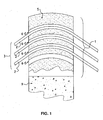
- it is a guide device 1 for the strands 2 of a cable 3 consisting of a plurality of strands 2.
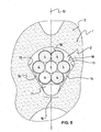
- the strands 2 each consist of several son 4, including metal.
- the strand 2 comprises a group of seven wires 4.
- the strands 2 shown have a cross section that fits in a circle, but they could also fit into an oval or other shape.
- a strand 2 which is similar to a strand type called “strand unsheathed”, but this is not limiting for the invention.
- Such an unsheathed strand is represented at figure 6 .
- a sheathed strand is a strand 2 whose constituent strands 4 are, over at least a part of their length, contained and / or enclosed in a sheath 40 formed by at least one tubular wall 41 ( figure 7 ), such a tubular wall 41 made of polyethylene material.
- a sheathed strand may also be a strand 2 whose constituent yarns 4 are, over at least part of their length, contained and / or enclosed in a sheath 40 formed by at least one wall comparable to a tubular wall 41, by a wall formed by coating ( figure 8 ), winding (not shown) or any other method.
- a wall formed by coating there may be mentioned a wall consisting of a layer of non-metallic material, for example polymer such as epoxy, or even a layer of metallic material, for example zinc.
- the device of the invention can be used with a strand 2 which is sheathed or with a strand 2 which is not sheathed.
- the guiding device 1 comprises a body 5 in which is formed at least one curved channel 6, comprising a longitudinal axis 7 curved according to the curvature of said channel 6 and at least a first portion 8 which, mainly located on the side of the intrados of the longitudinal axis 7, allows, in the limit of the length of the channel 6, the support of the strand 2 on at least a portion of the peripheral face 10 of said strand 2.
- longitudinal axis 7 is meant an axis which extends along the longitudinal dimension of the channel 6, but not necessarily in a median position relative to the transverse dimension of the channel 6 in a curvature plane 12 of this channel 6.
- the function of the longitudinal axis 7 indicated is to allow the definition of a lower surface and an upper surface, the lower surface being a first zone situated inside the curve formed by this surface.
- axis longitudinal 7 and the extrados being a second zone located outside the curve formed by said longitudinal axis 7.
- the guiding device 1 comprises a body 5 in which is formed at least one curved channel 6 with at least a second portion 11 which, mainly located on the extrados side of the longitudinal axis 7, is associated with the first part 8 and guides the strand 2 during its engagement in the channel 6, in particular, in order to conform it in a curvature plane 12 which contains the longitudinal axis 7 of the channel 6.
- peripheral face 10 of the strand 2 is constituted at least by the peripheral surface portions of the wires 4 which constitute it or, possibly, portions of the peripheral surface of a sheath 40 which covers these wires 4.
- the guide device 1 is constituted to define a support of the strand that can be described as bilateral support.
- This bilateral support is therefore of a chosen situation and of limited extent, so as to at least initiate a phenomenon of jamming of the strand 2.
- the jamming phenomenon occurs that the strand 2 comprises or does not include sheath 40.
- the guide device 1 is associated with a support 9, such as a pylon top (not shown).
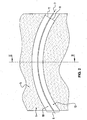
- the first two faces 13 are located on either side of the curvature plane 12.
- the first two faces 13 are symmetrically arranged with respect to the plane of curvature 12.
- the skilled person is able to determine the value of the angle that the first two faces 13 form, and this, at least by successive tests.
- the skilled person is also able to determine the value of the angle that the first two faces 13 form, and this, by calculation, according to the coefficient of friction between one and / or the other of these first faces 13 and the peripheral face 10 of the strand 2.
- the first faces 13 are each substantially planar.
- the first faces 13 may be smooth or have reliefs.
- the first faces 13 are connected by a second face 16 which is shaped and arranged to be subtracted from any contact with the strand 2 when the latter is in lateral support on the first faces 13.
- the second face 16 has transverse generatrices which each extend substantially perpendicularly to the plane of curvature 12.
- the second face 16 has transverse generatrices which are curved such that, seen in cross section, this second face 16 appears substantially concave.
- said second face 16 is positioned so as to be subtracted from any contact with the strand 2 when the latter is in lateral support on the first two faces 13.
- the guiding device 1 comprises at least one removable element 17 which, intended to be introduced into the channel 6 substantially before the introduction of a strand 2 and to be extracted from said channel 6 after introduction of said strand 2, is constituted to be placed in support on the second face 16 and, when placed in abutment on said second face 16, form a wedge which hinders the simultaneous support of the strand 2 on the first two faces 13.
- the longitudinal displacement of the strand 2 in the channel can be obtained without jamming or jamming primer.
- the removal of the removable element 17 makes it possible to bring the strand 2 to bear on the first two faces 13 and to cause at least one jamming primer of this strand 2.
- the second part 11 it is formed by a third face 18 defined by curved lines oriented to cause the sliding of the peripheral face 10 of the strand 2, during its engagement in the channel 6.
- the second portion 11 has a second cross section of substantially semicircular shape.
- the third face 18 and the second face 16 are at least sufficiently spaced apart so that, when a removable element 17 is placed in abutment on the second face 16, it can perform its function without the engagement and sliding of a strand 2 in the channel 6 is impeded by contact with the third face 18.
- the channels of the guiding device can also be constituted by formwork.
- the invention also relates to constructions comprising the guiding device which has just been described.
Landscapes
- Engineering & Computer Science (AREA)
- General Engineering & Computer Science (AREA)
- Architecture (AREA)
- Civil Engineering (AREA)
- Structural Engineering (AREA)
- Mechanical Engineering (AREA)
- Ropes Or Cables (AREA)
- Reinforcement Elements For Buildings (AREA)
- Media Introduction/Drainage Providing Device (AREA)
- Bridges Or Land Bridges (AREA)
Priority Applications (1)
| Application Number | Priority Date | Filing Date | Title |
|---|---|---|---|
| PL06754767T PL2007947T3 (pl) | 2006-04-20 | 2006-04-20 | Urządzenie prowadzące dla żył |
Applications Claiming Priority (1)
| Application Number | Priority Date | Filing Date | Title |
|---|---|---|---|
| PCT/EP2006/061709 WO2007121782A1 (fr) | 2006-04-20 | 2006-04-20 | Dispositif de guidage pour torons |
Publications (2)
| Publication Number | Publication Date |
|---|---|
| EP2007947A1 EP2007947A1 (fr) | 2008-12-31 |
| EP2007947B1 true EP2007947B1 (fr) | 2014-05-14 |
Family
ID=37602968
Family Applications (1)
| Application Number | Title | Priority Date | Filing Date |
|---|---|---|---|
| EP06754767.9A Active EP2007947B1 (fr) | 2006-04-20 | 2006-04-20 | Dispositif de guidage pour torons |
Country Status (9)
| Country | Link |
|---|---|
| US (1) | US7900306B2 (pl) |
| EP (1) | EP2007947B1 (pl) |
| JP (1) | JP4901954B2 (pl) |
| KR (1) | KR101255568B1 (pl) |
| CN (1) | CN101421463B (pl) |
| AU (1) | AU2006342459B2 (pl) |
| ES (1) | ES2492568T3 (pl) |
| PL (1) | PL2007947T3 (pl) |
| WO (1) | WO2007121782A1 (pl) |
Families Citing this family (13)
| Publication number | Priority date | Publication date | Assignee | Title |
|---|---|---|---|---|
| BR112012023929B1 (pt) * | 2010-03-26 | 2019-07-02 | Vsl International Ag | Travessão de ponte e método para proteger cordas de corrosão em um travessão de ponte |
| FR2968681B1 (fr) | 2010-12-08 | 2015-05-29 | Soletanche Freyssinet | Dispositif de deviation d'un cable de structure tel qu'un hauban, et ouvrage ainsi equipe |
| US9175485B2 (en) * | 2011-08-12 | 2015-11-03 | Vsl International Ag | Tension member feeding device |
| PL2703331T3 (pl) * | 2012-09-03 | 2015-06-30 | Soletanche Freyssinet | System ciągowy stosujący linę wielocięgnową z kątem odchylenia |
| CN102912727A (zh) * | 2012-11-02 | 2013-02-06 | 江阴法尔胜住电新材料有限公司 | 能抵抗斜拉索钢绞线滑移的部分斜拉桥分丝管索鞍 |
| CN102966040B (zh) * | 2012-11-21 | 2016-02-17 | 安徽佳路机械制造有限公司 | 一种斜拉桥索鞍及其制造方法 |
| CN103015319B (zh) * | 2013-01-07 | 2015-06-17 | 合肥斯派索材料科技有限公司 | 用于斜拉桥索塔拉索转向器的雨滴形不锈钢分丝管 |
| CN103266565A (zh) * | 2013-05-31 | 2013-08-28 | 中交二航局第四工程有限公司安徽分公司 | 一种插销式钢绞线阻拦装置 |
| CN105445181A (zh) * | 2015-11-25 | 2016-03-30 | 安徽金星预应力工程技术有限公司 | 斜拉索水滴型索鞍预应力孔道摩擦系数的测定方法 |
| DE102016225416A1 (de) * | 2016-12-19 | 2018-06-21 | Dywidag-Systems International Gmbh | Verfahren zum Installieren eines Spannelements in einem Ankerblock, Halterung, insbesondere zur Durchführung des Verfahrens und Kombination einer Halterung mit einem Spannelement |
| WO2022111811A1 (en) | 2020-11-27 | 2022-06-02 | Dywidag-Systems International Gmbh | Guiding device and combination of a guiding device with at least one strand |
| MX2024006330A (es) * | 2021-11-24 | 2024-06-21 | Felix Sorkin | Soporte de mezcla de polímeros para puente atirantado. |
| US11949217B1 (en) * | 2022-09-19 | 2024-04-02 | EcoFasten Solar, LLC | Wire clamp |
Family Cites Families (15)
| Publication number | Priority date | Publication date | Assignee | Title |
|---|---|---|---|---|
| DE1804564A1 (de) | 1968-10-23 | 1970-05-27 | Porsche Kg | Stromversorgungsgeraet fuer Entladungslampen |
| GB1277489A (en) | 1969-11-08 | 1972-06-14 | Carves Simon Ltd | Improvements in or relating to prestressed structures |
| FR2511721A1 (fr) * | 1981-08-21 | 1983-02-25 | Freyssinet Int Stup | Dispositif de raccordement incurve entre deux portions rectilignes d'un cable tendu |
| DE3734953C2 (de) * | 1987-03-13 | 1994-02-24 | Dyckerhoff & Widmann Ag | Abstandhalter für ein spannbares Zugglied |
| DE8810423U1 (de) | 1988-08-18 | 1988-11-10 | Dyckerhoff & Widmann AG, 8000 München | Vorrichtung zur Auflagerung eines Zugglieds an einer Abstützung |
| ES2042271T5 (es) * | 1989-04-12 | 1997-11-01 | Vorspann Technik Gmbh | Grupo tensor de varios elementos tensores como cordones, varillas o alambres. |
| JPH0772446A (ja) * | 1993-09-01 | 1995-03-17 | Sharp Corp | 表示システム |
| JPH07269023A (ja) * | 1994-03-29 | 1995-10-17 | Sumitomo Electric Ind Ltd | 緊張ケーブルの保護構造並びにその保護スペーサ |
| DE29813941U1 (de) * | 1998-08-04 | 1999-12-09 | Dyckerhoff & Widmann AG, 81902 München | Umlenkvorrichtung für ein Spannglied an einem Bauwerksteil |
| DE19928445B4 (de) * | 1999-06-23 | 2007-10-04 | Suspa Spannbeton Gmbh | Ausbildung einer Umlenk-Gleitstelle für Spannglieder |
| DE19934872B4 (de) | 1999-07-24 | 2005-09-22 | Bilfinger Berger Ag | Aussparungskörper und Verfahren zu seiner Herstellung |
| DE10062227A1 (de) * | 2000-12-13 | 2002-06-20 | Dyckerhoff & Widmann Ag | Verfahren zum Einbauen und Spannen eines freigespannten Zugglieds, insbesondere eines Schrägseils für eine Schrägseilbrücke sowie Verankerungsvorrichtung zum Durchführen des Verfahrens |
| US6880193B2 (en) * | 2002-04-02 | 2005-04-19 | Figg Bridge Engineers, Inc. | Cable-stay cradle system |
| DE202004008621U1 (de) * | 2004-06-01 | 2005-10-06 | Dywidag-Systems International Gmbh | Ausbildung eines korrosionsgeschützten Zugglieds im Bereich seines Eintritts in ein Bauwerk, insbesondere eines Schrägseils am Pylon einer Schrägseilbrücke |
| CN2761733Y (zh) * | 2004-12-28 | 2006-03-01 | 重庆交通科研设计院 | 绞线锚固防滑器 |
-
2006
- 2006-04-20 EP EP06754767.9A patent/EP2007947B1/fr active Active
- 2006-04-20 PL PL06754767T patent/PL2007947T3/pl unknown
- 2006-04-20 CN CN2006800542795A patent/CN101421463B/zh active Active
- 2006-04-20 KR KR1020087025458A patent/KR101255568B1/ko active Active
- 2006-04-20 AU AU2006342459A patent/AU2006342459B2/en active Active
- 2006-04-20 ES ES06754767.9T patent/ES2492568T3/es active Active
- 2006-04-20 JP JP2009505730A patent/JP4901954B2/ja active Active
- 2006-04-20 US US12/296,325 patent/US7900306B2/en active Active
- 2006-04-20 WO PCT/EP2006/061709 patent/WO2007121782A1/fr not_active Ceased
Also Published As
| Publication number | Publication date |
|---|---|
| EP2007947A1 (fr) | 2008-12-31 |
| CN101421463A (zh) | 2009-04-29 |
| KR20090005325A (ko) | 2009-01-13 |
| JP2009534555A (ja) | 2009-09-24 |
| US20090158535A1 (en) | 2009-06-25 |
| CN101421463B (zh) | 2011-09-07 |
| HK1131416A1 (en) | 2010-01-22 |
| JP4901954B2 (ja) | 2012-03-21 |
| KR101255568B1 (ko) | 2013-04-17 |
| AU2006342459A1 (en) | 2007-11-01 |
| ES2492568T3 (es) | 2014-09-09 |
| PL2007947T3 (pl) | 2014-11-28 |
| US7900306B2 (en) | 2011-03-08 |
| WO2007121782A1 (fr) | 2007-11-01 |
| AU2006342459B2 (en) | 2011-11-24 |
Similar Documents
| Publication | Publication Date | Title |
|---|---|---|
| EP2007947B1 (fr) | Dispositif de guidage pour torons | |
| FR2742489A1 (fr) | Attaches flexibles et, plus particulierement, des attaches du type a entree parallele | |
| FR2511721A1 (fr) | Dispositif de raccordement incurve entre deux portions rectilignes d'un cable tendu | |
| CH634786A5 (fr) | Jonction a verrouillage pour le guidage d'un element portant une charge. | |
| WO2015118401A1 (fr) | Gaine tubulaire annelée comportant un moyen intérieur de serrage | |
| CA3157072A1 (fr) | Dispositif pour separer l'ame et la gaine d'un cable et procede de separation de l'ame et la gaine d'un cable | |
| CA2296981C (fr) | Pince a cheveux a dents appariees | |
| EP3309034B1 (fr) | Dispositif et procede de repositionnement du cable porteur d'une installation de transport par cable | |
| FR2610656A1 (fr) | Dispositif pour guider les cables de precontrainte d'un ouvrage de genie civil | |
| FR2763083A1 (fr) | Barriere dynamique d'arret de chutes de pierres a boucles de dissipation d'energie | |
| EP2303729B1 (fr) | Bande transporteuse sans fin et dispositif convoyeur la comprenant | |
| EP3563067B1 (fr) | Dispositif de cerclage | |
| EP3327325B1 (fr) | Dispositif conçu pour fixer au moins un cable le long d'un conduit, et procede de mise en oeuvre d'un tel dispositif | |
| EP0465303B1 (fr) | Perfectionnements aux ponts à haubans et plus particulièrement à leurs pylônes et haubans | |
| FR2765249A1 (fr) | Procede pour poser une gaine en forme de tube sur une membrure tendue et dispositif pour ecarter une gaine en forme de tube | |
| FR2744467A1 (fr) | Dispositif de suspension pour ouvrage de genie civil et procede de construction | |
| FR2524582A1 (fr) | Collier de serrage | |
| EP1121492B1 (fr) | Deviateur pour cable de hauban | |
| FR3094739A3 (fr) | Chaîne de guidage d’énergie pour une fraise pour parois moulés | |
| FR2593434A1 (fr) | Mecanisme d'etirage transversal et en continu d'un film plastique | |
| EP0572315A1 (fr) | Perfectionnements aux dispositifs pour effectuer des ancrages intermédiaires sur des câbles de précontrainte | |
| EP2671698B1 (fr) | Banc de fabrication de poutrelles par filage | |
| EP2850259A1 (fr) | Barre d'armature a adherence amelioree et procédé de réalisation | |
| FR2826426A1 (fr) | Procede pour poser, dans une tranchee, au moins un objet allonge, unite mobile pour mettre en oeuvre ledit procede et element prefabrique a poser, avec ledit objet allonge, dans ladite tranchee | |
| FR3121456A1 (fr) | Procede pour ôter une armature d’un cable de structure et systeme associe |
Legal Events
| Date | Code | Title | Description |
|---|---|---|---|
| PUAI | Public reference made under article 153(3) epc to a published international application that has entered the european phase |
Free format text: ORIGINAL CODE: 0009012 |
|
| 17P | Request for examination filed |
Effective date: 20080926 |
|
| AK | Designated contracting states |
Kind code of ref document: A1 Designated state(s): AT BE BG CH CY CZ DE DK EE ES FI FR GB GR HU IE IS IT LI LT LU LV MC NL PL PT RO SE SI SK TR |
|
| AX | Request for extension of the european patent |
Extension state: AL BA HR MK YU |
|
| 17Q | First examination report despatched |
Effective date: 20101110 |
|
| RAP1 | Party data changed (applicant data changed or rights of an application transferred) |
Owner name: VSL INTERNATIONAL AG |
|
| DAX | Request for extension of the european patent (deleted) | ||
| GRAP | Despatch of communication of intention to grant a patent |
Free format text: ORIGINAL CODE: EPIDOSNIGR1 |
|
| INTG | Intention to grant announced |
Effective date: 20131205 |
|
| GRAS | Grant fee paid |
Free format text: ORIGINAL CODE: EPIDOSNIGR3 |
|
| GRAA | (expected) grant |
Free format text: ORIGINAL CODE: 0009210 |
|
| AK | Designated contracting states |
Kind code of ref document: B1 Designated state(s): AT BE BG CH CY CZ DE DK EE ES FI FR GB GR HU IE IS IT LI LT LU LV MC NL PL PT RO SE SI SK TR |
|
| REG | Reference to a national code |
Ref country code: GB Ref legal event code: FG4D Free format text: NOT ENGLISH |
|
| REG | Reference to a national code |
Ref country code: AT Ref legal event code: REF Ref document number: 668416 Country of ref document: AT Kind code of ref document: T Effective date: 20140615 |
|
| REG | Reference to a national code |
Ref country code: IE Ref legal event code: FG4D Free format text: LANGUAGE OF EP DOCUMENT: FRENCH |
|
| REG | Reference to a national code |
Ref country code: DE Ref legal event code: R096 Ref document number: 602006041583 Country of ref document: DE Effective date: 20140626 |
|
| REG | Reference to a national code |
Ref country code: CH Ref legal event code: NV Representative=s name: P&TS SA, CH |
|
| REG | Reference to a national code |
Ref country code: SE Ref legal event code: TRGR |
|
| REG | Reference to a national code |
Ref country code: ES Ref legal event code: FG2A Ref document number: 2492568 Country of ref document: ES Kind code of ref document: T3 Effective date: 20140909 |
|
| REG | Reference to a national code |
Ref country code: NL Ref legal event code: VDEP Effective date: 20140514 Ref country code: AT Ref legal event code: MK05 Ref document number: 668416 Country of ref document: AT Kind code of ref document: T Effective date: 20140514 |
|
| REG | Reference to a national code |
Ref country code: LT Ref legal event code: MG4D |
|
| PG25 | Lapsed in a contracting state [announced via postgrant information from national office to epo] |
Ref country code: IS Free format text: LAPSE BECAUSE OF FAILURE TO SUBMIT A TRANSLATION OF THE DESCRIPTION OR TO PAY THE FEE WITHIN THE PRESCRIBED TIME-LIMIT Effective date: 20140914 Ref country code: LT Free format text: LAPSE BECAUSE OF FAILURE TO SUBMIT A TRANSLATION OF THE DESCRIPTION OR TO PAY THE FEE WITHIN THE PRESCRIBED TIME-LIMIT Effective date: 20140514 Ref country code: GR Free format text: LAPSE BECAUSE OF FAILURE TO SUBMIT A TRANSLATION OF THE DESCRIPTION OR TO PAY THE FEE WITHIN THE PRESCRIBED TIME-LIMIT Effective date: 20140815 Ref country code: FI Free format text: LAPSE BECAUSE OF FAILURE TO SUBMIT A TRANSLATION OF THE DESCRIPTION OR TO PAY THE FEE WITHIN THE PRESCRIBED TIME-LIMIT Effective date: 20140514 Ref country code: CY Free format text: LAPSE BECAUSE OF FAILURE TO SUBMIT A TRANSLATION OF THE DESCRIPTION OR TO PAY THE FEE WITHIN THE PRESCRIBED TIME-LIMIT Effective date: 20140514 |
|
| PG25 | Lapsed in a contracting state [announced via postgrant information from national office to epo] |
Ref country code: AT Free format text: LAPSE BECAUSE OF FAILURE TO SUBMIT A TRANSLATION OF THE DESCRIPTION OR TO PAY THE FEE WITHIN THE PRESCRIBED TIME-LIMIT Effective date: 20140514 Ref country code: LV Free format text: LAPSE BECAUSE OF FAILURE TO SUBMIT A TRANSLATION OF THE DESCRIPTION OR TO PAY THE FEE WITHIN THE PRESCRIBED TIME-LIMIT Effective date: 20140514 |
|
| REG | Reference to a national code |
Ref country code: PL Ref legal event code: T3 |
|
| PG25 | Lapsed in a contracting state [announced via postgrant information from national office to epo] |
Ref country code: PT Free format text: LAPSE BECAUSE OF FAILURE TO SUBMIT A TRANSLATION OF THE DESCRIPTION OR TO PAY THE FEE WITHIN THE PRESCRIBED TIME-LIMIT Effective date: 20140915 |
|
| PG25 | Lapsed in a contracting state [announced via postgrant information from national office to epo] |
Ref country code: RO Free format text: LAPSE BECAUSE OF FAILURE TO SUBMIT A TRANSLATION OF THE DESCRIPTION OR TO PAY THE FEE WITHIN THE PRESCRIBED TIME-LIMIT Effective date: 20140514 Ref country code: EE Free format text: LAPSE BECAUSE OF FAILURE TO SUBMIT A TRANSLATION OF THE DESCRIPTION OR TO PAY THE FEE WITHIN THE PRESCRIBED TIME-LIMIT Effective date: 20140514 Ref country code: DK Free format text: LAPSE BECAUSE OF FAILURE TO SUBMIT A TRANSLATION OF THE DESCRIPTION OR TO PAY THE FEE WITHIN THE PRESCRIBED TIME-LIMIT Effective date: 20140514 Ref country code: CZ Free format text: LAPSE BECAUSE OF FAILURE TO SUBMIT A TRANSLATION OF THE DESCRIPTION OR TO PAY THE FEE WITHIN THE PRESCRIBED TIME-LIMIT Effective date: 20140514 Ref country code: SK Free format text: LAPSE BECAUSE OF FAILURE TO SUBMIT A TRANSLATION OF THE DESCRIPTION OR TO PAY THE FEE WITHIN THE PRESCRIBED TIME-LIMIT Effective date: 20140514 |
|
| REG | Reference to a national code |
Ref country code: DE Ref legal event code: R097 Ref document number: 602006041583 Country of ref document: DE |
|
| PG25 | Lapsed in a contracting state [announced via postgrant information from national office to epo] |
Ref country code: NL Free format text: LAPSE BECAUSE OF FAILURE TO SUBMIT A TRANSLATION OF THE DESCRIPTION OR TO PAY THE FEE WITHIN THE PRESCRIBED TIME-LIMIT Effective date: 20140514 |
|
| PLBE | No opposition filed within time limit |
Free format text: ORIGINAL CODE: 0009261 |
|
| STAA | Information on the status of an ep patent application or granted ep patent |
Free format text: STATUS: NO OPPOSITION FILED WITHIN TIME LIMIT |
|
| 26N | No opposition filed |
Effective date: 20150217 |
|
| REG | Reference to a national code |
Ref country code: DE Ref legal event code: R097 Ref document number: 602006041583 Country of ref document: DE Effective date: 20150217 |
|
| PG25 | Lapsed in a contracting state [announced via postgrant information from national office to epo] |
Ref country code: SI Free format text: LAPSE BECAUSE OF FAILURE TO SUBMIT A TRANSLATION OF THE DESCRIPTION OR TO PAY THE FEE WITHIN THE PRESCRIBED TIME-LIMIT Effective date: 20140514 |
|
| PG25 | Lapsed in a contracting state [announced via postgrant information from national office to epo] |
Ref country code: LU Free format text: LAPSE BECAUSE OF FAILURE TO SUBMIT A TRANSLATION OF THE DESCRIPTION OR TO PAY THE FEE WITHIN THE PRESCRIBED TIME-LIMIT Effective date: 20150420 Ref country code: MC Free format text: LAPSE BECAUSE OF FAILURE TO SUBMIT A TRANSLATION OF THE DESCRIPTION OR TO PAY THE FEE WITHIN THE PRESCRIBED TIME-LIMIT Effective date: 20140514 |
|
| REG | Reference to a national code |
Ref country code: IE Ref legal event code: MM4A |
|
| REG | Reference to a national code |
Ref country code: FR Ref legal event code: PLFP Year of fee payment: 11 |
|
| PG25 | Lapsed in a contracting state [announced via postgrant information from national office to epo] |
Ref country code: IE Free format text: LAPSE BECAUSE OF NON-PAYMENT OF DUE FEES Effective date: 20150420 |
|
| REG | Reference to a national code |
Ref country code: FR Ref legal event code: PLFP Year of fee payment: 12 |
|
| PG25 | Lapsed in a contracting state [announced via postgrant information from national office to epo] |
Ref country code: HU Free format text: LAPSE BECAUSE OF FAILURE TO SUBMIT A TRANSLATION OF THE DESCRIPTION OR TO PAY THE FEE WITHIN THE PRESCRIBED TIME-LIMIT; INVALID AB INITIO Effective date: 20060420 Ref country code: BG Free format text: LAPSE BECAUSE OF FAILURE TO SUBMIT A TRANSLATION OF THE DESCRIPTION OR TO PAY THE FEE WITHIN THE PRESCRIBED TIME-LIMIT Effective date: 20140514 |
|
| PG25 | Lapsed in a contracting state [announced via postgrant information from national office to epo] |
Ref country code: BE Free format text: LAPSE BECAUSE OF NON-PAYMENT OF DUE FEES Effective date: 20150430 |
|
| PG25 | Lapsed in a contracting state [announced via postgrant information from national office to epo] |
Ref country code: TR Free format text: LAPSE BECAUSE OF FAILURE TO SUBMIT A TRANSLATION OF THE DESCRIPTION OR TO PAY THE FEE WITHIN THE PRESCRIBED TIME-LIMIT Effective date: 20140514 |
|
| REG | Reference to a national code |
Ref country code: FR Ref legal event code: PLFP Year of fee payment: 13 |
|
| REG | Reference to a national code |
Ref country code: DE Ref legal event code: R082 Ref document number: 602006041583 Country of ref document: DE Representative=s name: BECK & ROESSIG EUROPEAN PATENT ATTORNEYS, DE Ref country code: DE Ref legal event code: R082 Ref document number: 602006041583 Country of ref document: DE Representative=s name: BECK & ROESSIG - EUROPEAN PATENT ATTORNEYS, DE |
|
| P01 | Opt-out of the competence of the unified patent court (upc) registered |
Free format text: CASE NUMBER: APP_63917/2024 Effective date: 20241202 |
|
| PGFP | Annual fee paid to national office [announced via postgrant information from national office to epo] |
Ref country code: PL Payment date: 20250319 Year of fee payment: 20 |
|
| PGFP | Annual fee paid to national office [announced via postgrant information from national office to epo] |
Ref country code: DE Payment date: 20250422 Year of fee payment: 20 |
|
| PGFP | Annual fee paid to national office [announced via postgrant information from national office to epo] |
Ref country code: ES Payment date: 20250529 Year of fee payment: 20 Ref country code: GB Payment date: 20250418 Year of fee payment: 20 |
|
| PGFP | Annual fee paid to national office [announced via postgrant information from national office to epo] |
Ref country code: IT Payment date: 20250424 Year of fee payment: 20 |
|
| PGFP | Annual fee paid to national office [announced via postgrant information from national office to epo] |
Ref country code: FR Payment date: 20250424 Year of fee payment: 20 |
|
| PGFP | Annual fee paid to national office [announced via postgrant information from national office to epo] |
Ref country code: CH Payment date: 20250501 Year of fee payment: 20 |
|
| PGFP | Annual fee paid to national office [announced via postgrant information from national office to epo] |
Ref country code: SE Payment date: 20250429 Year of fee payment: 20 |