EP2007542B1 - Procede de soudage d'une piece - Google Patents
Procede de soudage d'une piece Download PDFInfo
- Publication number
- EP2007542B1 EP2007542B1 EP07701312A EP07701312A EP2007542B1 EP 2007542 B1 EP2007542 B1 EP 2007542B1 EP 07701312 A EP07701312 A EP 07701312A EP 07701312 A EP07701312 A EP 07701312A EP 2007542 B1 EP2007542 B1 EP 2007542B1
- Authority
- EP
- European Patent Office
- Prior art keywords
- welding
- workpiece
- welding wire
- slag
- wire
- Prior art date
- Legal status (The legal status is an assumption and is not a legal conclusion. Google has not performed a legal analysis and makes no representation as to the accuracy of the status listed.)
- Active
Links
- 238000003466 welding Methods 0.000 title claims abstract description 270
- 238000000034 method Methods 0.000 title claims abstract description 156
- 239000002893 slag Substances 0.000 claims abstract description 90
- 238000012544 monitoring process Methods 0.000 claims abstract description 12
- 238000010891 electric arc Methods 0.000 claims abstract description 9
- 230000000306 recurrent effect Effects 0.000 claims abstract description 7
- 125000004122 cyclic group Chemical group 0.000 claims description 3
- 238000001514 detection method Methods 0.000 abstract description 4
- 230000015572 biosynthetic process Effects 0.000 description 4
- 238000001816 cooling Methods 0.000 description 4
- 239000007788 liquid Substances 0.000 description 4
- 239000002184 metal Substances 0.000 description 4
- 230000006641 stabilisation Effects 0.000 description 4
- 238000011105 stabilization Methods 0.000 description 4
- 238000010586 diagram Methods 0.000 description 3
- 238000002844 melting Methods 0.000 description 3
- 230000008018 melting Effects 0.000 description 3
- XKRFYHLGVUSROY-UHFFFAOYSA-N Argon Chemical compound [Ar] XKRFYHLGVUSROY-UHFFFAOYSA-N 0.000 description 2
- 101100043261 Caenorhabditis elegans spop-1 gene Proteins 0.000 description 2
- 230000002411 adverse Effects 0.000 description 2
- 230000033228 biological regulation Effects 0.000 description 2
- 230000008878 coupling Effects 0.000 description 2
- 238000010168 coupling process Methods 0.000 description 2
- 238000005859 coupling reaction Methods 0.000 description 2
- 239000000945 filler Substances 0.000 description 2
- 239000007789 gas Substances 0.000 description 2
- 238000010438 heat treatment Methods 0.000 description 2
- 239000000463 material Substances 0.000 description 2
- 238000003825 pressing Methods 0.000 description 2
- 230000001105 regulatory effect Effects 0.000 description 2
- XLYOFNOQVPJJNP-UHFFFAOYSA-N water Substances O XLYOFNOQVPJJNP-UHFFFAOYSA-N 0.000 description 2
- 229910000851 Alloy steel Inorganic materials 0.000 description 1
- 229910000831 Steel Inorganic materials 0.000 description 1
- 239000000853 adhesive Substances 0.000 description 1
- 230000001070 adhesive effect Effects 0.000 description 1
- 229910052786 argon Inorganic materials 0.000 description 1
- 230000001276 controlling effect Effects 0.000 description 1
- 239000001307 helium Substances 0.000 description 1
- 229910052734 helium Inorganic materials 0.000 description 1
- SWQJXJOGLNCZEY-UHFFFAOYSA-N helium atom Chemical compound [He] SWQJXJOGLNCZEY-UHFFFAOYSA-N 0.000 description 1
- 230000000704 physical effect Effects 0.000 description 1
- 230000002035 prolonged effect Effects 0.000 description 1
- 230000003252 repetitive effect Effects 0.000 description 1
- 238000005476 soldering Methods 0.000 description 1
- 239000010959 steel Substances 0.000 description 1
Images

Classifications
-
- B—PERFORMING OPERATIONS; TRANSPORTING
- B23—MACHINE TOOLS; METAL-WORKING NOT OTHERWISE PROVIDED FOR
- B23K—SOLDERING OR UNSOLDERING; WELDING; CLADDING OR PLATING BY SOLDERING OR WELDING; CUTTING BY APPLYING HEAT LOCALLY, e.g. FLAME CUTTING; WORKING BY LASER BEAM
- B23K9/00—Arc welding or cutting
- B23K9/06—Arrangements or circuits for starting the arc, e.g. by generating ignition voltage, or for stabilising the arc
- B23K9/073—Stabilising the arc
- B23K9/0737—Stabilising of the arc position
Definitions
- the invention relates to a method for welding a workpiece according to the preamble of claim 1, comprising a welding torch with a consumable welding wire, which during a welding process, during which an arc between the welding wire and the workpiece burns, by means of a wire feed device substantially in the direction of the workpiece is moved, wherein a process for removing slag at the end of the welding wire is started and carried out.
- the welding wire is pressed against the surface of the workpiece with a certain pressure, thereby removing the slag. Also, this can lead to damage of the welding wire.
- the JP 2000-153358 A describes an ignition method in which the welding torch with the welding wire is moved so far in the direction of the workpiece until the welding wire touches the workpiece. If the contact voltage does not go to zero, this is an indication of the presence of slag, after which the burner is moved back to the starting position and back to the workpiece.
- the object of the invention is to provide a welding method which is not adversely affected by an optionally adhering to the end of the welding wire to be contacted slag and ensures a safe ignition of the arc.
- the object of the invention is achieved in that with the beginning of the slag removal process, the welding current is reduced to a minimum, and the slag removal process of the Welding torch performs no movement and the welding wire with a fast recurring forward / backward movement cyclically a predetermined path length in the direction of the workpiece and a smaller distance away from the workpiece, so that the promotion of the welding wire to the workpiece outweighs of a short circuit monitoring a short circuit between the Welding wire and the workpiece is detected, whereupon the slag removal process is terminated.
- the welding process not interrupted due to a slag adhering to the end of the welding wire to be contacted, which prevents ignition of the arc.
- the slag removal process ensures that the arc is safely ignited for the following welding process, essentially without a time delay.
- the slag removal process can be implemented relatively easily in a suitable welding apparatus, since a short-circuit monitoring known per se can be used to detect the short circuit.
- the measure of reducing the welding current to a minimum at the beginning of the slag removal process prevents the arc from being ignited during this time, while detecting a short circuit.
- the slag removal process may be performed at a time interval at the beginning of an ignition process, at a time interval during an ignition process, or at a time interval before an ignition process.
- the arc is preferably ignited by a so-called SPI (spatter free ignition) ignition method, in which the welding wire is subjected to a small welding current and continuously moves in the direction of the workpiece until it contacts the workpiece is, after the occurrence of a short circuit, the wire conveying direction is reversed and the welding wire is continuously moved away from the workpiece, so that when lifting the welding wire, the arc is ignited.
- the welding wire is moved back to a predefined distance to the workpiece. So before the SFI ignition process, the slag removal process is carried out, with the removal of the slag takes place automatically until the detection of the short circuit.
- the ignition process of the arc which is adapted to the respective welding process, is not adversely affected by the slag removal process.
- the welding wire is substantially conveyed toward the workpiece, thereby increasing the impact force of the welding wire on the workpiece, thus accelerating the removal of the slag.
- the motor current of the wire feeder is monitored and at least the first contact of the welding wire with the workpiece is detected. As a result, it can be prevented that the workpiece is deformed by the conveying force of the welding wire, even if no short circuit has yet been detected by the short circuit monitoring, and thus the slag removal process has not yet been completed.
- the touch of the welding wire is detected by exceeding a predetermined limit value of the motor current over a defined period of time.
- the cyclic, fast returning forward / backward movement of the welding wire for the purpose of removing the slag is preferably carried out at an adjustable frequency between 50 Hz and 150 Hz. This relatively high frequency ensures that the welding process is not significantly prolonged by the duration of the slag removal process.
- the cyclical, fast-forward / backward movement of the welding wire for the purpose of removing the slag is carried out at a frequency which corresponds to the frequency of movement of the welding wire during the set welding process.
- the welding current is increased to a value required for the subsequent ignition process, thus enabling the arc to be ignited immediately after the end of the slag removal process.
- the set time preferably starts when the welding wire touches the workpiece for the first time without a Short circuit was detected.
- Fig. 1 is a welding machine 1 or a welding system for a variety of processes or procedures, such as MIG / MAG welding or TIG / TIG welding or electrode welding process, double wire / tandem welding process, plasma or soldering, etc., shown.
- the welding device 1 comprises a current source 2 with a power part 3, a control device 4 and a switching element 5 assigned to the power part 3 or the control device 4.
- the switching element 5 or the control device 4 is connected to a control valve 6 which is located in a supply line 7 for a shielding gas 8, such as CO 2 , helium or argon and the like., Between a gas storage 9 and a welding torch 10 and a burner is arranged.
- a wire feed device 11 which is customary for MIG / MAG welding, can be actuated via the control device 4, wherein a filler material or a welding wire 13 is supplied from a wire roll 14 into the region of the welding torch 10 via a supply line 12.
- the wire feeder 11 can also be integrated in the welding device 1, in particular in the base housing, and not, as in Fig. 1 represented, be designed as an accessory.
- the wire feeder 11 may supply the welding wire 13 outside the welding torch 10 to the processing station, for which purpose a non-consumable electrode is preferably arranged in the welding torch 10, as is usual in TIG / TIG welding.
- the current for establishing an arc 15, between the non-consumable electrode or the welding wire 13 and a workpiece 16 is supplied via a welding line 17 from the power section 3 of the power source 2 to the welding torch 10, in particular the electrode, wherein the workpieces 16 to be welded via a Further welding line 18 are also connected to the welding device 1, in particular to the power source 2, and thus can be constructed via the arc 15 and the plasma jet formed for a process, a circuit.
- the welding torch 10 can be connected via a cooling circuit 20 to a liquid container, in particular a water tank 21, whereby during commissioning of the welding torch 10 the cooling circuit 19, in particular a liquid arranged in the water tank 21 used liquid pump is started, and thus a cooling of the welding torch 10 can be effected.
- the welding device 1 further has an input and / or output device 22, via which the most varied welding parameters, operating modes or welding programs of the welding device 1 can be set or called up.
- the welding parameters, operating modes or welding programs set via the input and / or output device 22 are forwarded to the control device 4 and from this the individual components of the welding device 1 are subsequently controlled or corresponding setpoint values are input for the control or regulation.
- the welding torch 10 is connected via a hose package 23 to the welding device 1.
- the individual lines from the welding device 1 to the welding torch 10 are arranged.
- the Hose package 23 is connected via a coupling device 24 with the welding torch 10, whereas the individual lines are connected in the hose package 23 with the individual contacts of the welding device 1 via connection sockets or connectors. So that a corresponding strain relief of the hose assembly 23 is ensured, the hose package 23 is connected via a strain relief device 25 with a housing 26, in particular with the base housing of the welding device 1.
- the coupling device 24 can be used for the connection to the welding device 1.
- the welding torch 10 For the different welding methods or welding devices 1, such as TIG devices or MIG / MAG devices or plasma devices, not all previously named components must be used or used. For example, it is possible to carry out the welding torch 10 as an air-cooled welding torch 10.
- a welding process for example a cold metal transfer welding process, hereinafter referred to as CMT (cold metal transfer) process
- CMT cold metal transfer
- a welding process is always started with an ignition of the arc 15, wherein the ignition can be effected for example by a contact ignition or a high-frequency ignition.
- the ignition method for igniting the arc 15 takes place via the lift-arc principle known from the prior art or with the spatter-free ignition (SFI) ignition process.
- SFI spatter-free ignition
- the welding wire 13 is continuously conveyed with a small welding current to the contact with the workpiece 16, whereupon after the occurrence of a short circuit, the wire conveying direction is reversed and the welding wire 13 is moved away from the workpiece 16 continuously, so that when lifting the welding wire 13 of the arc 15 is ignited and optionally the welding wire 13 is conveyed back to a predefined distance to the workpiece 16. This results in the formation of the arc 15, whereby now the actual welding process can be started.
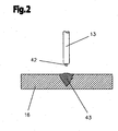
- the welding wire 13 is moved back from a molten bath 43, with a part of the slag 42 located on the surface of the molten bath 43 adhering to the end of the welding wire 13.
- slag 42 may form at the end of the welding wire 13 when, at the end of the welding process, the liquid end of the welding wire 13 solidifies. This often happens when welding steel or steel alloys.
- the slag 42 prevents or impedes the ignition of the arc 15 at the start of the welding process, since no current flow from the welding wire 13 to the workpiece 16 is achieved.
- Another possibility would be to change the angle of incidence of the welding wire 13 to the workpiece 16, whereby possibly the conductive welding wire 13 contacted with the workpiece 16 at the edge zone of the slag 42, a short circuit is detected and by reversing the conveying direction of the welding wire 13 of the arc 15 is ignited.
- the slag 42 at the end of the welding wire 13 is removed by a corresponding movement of the welding wire 13.
- the welding wire 13 is cyclically at high speed back a certain distance before and a smaller distance than forward again. This results in repeated, jerky contact with the slag 42, contacting end of the welding wire 13 with the workpiece 16, whereby the slag 42 is released from the end of the welding wire 13 by the mechanical force upon impact of the welding wire 13 on the workpiece 16.
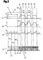
- Fig. 3 is the inventive method for removing the slag 42 from the end of the welding wire 13 during a CMT welding process, with reference to the diagrams 27 to 30, the timing of the welding voltage U, the welding current I, the wire feed speed, and the movements or the end positions of the welding wire 13 relative to the workpiece 16, shown schematically.
- a consumable electrode or a welding wire 13 is used.
- the melting of the workpiece 16 and the welding wire 13 via the ionized plasma column or the arc 15, which takes place between the welding wire 13 and the electrical opposite pole built on the workpiece 16, that is ignited is.
- the ignition phase 31 is started in such a way, for example, by the user pressing a button on the welding torch 10 or doing so automatically.
- the slag removal process takes place in a time interval 47 of the ignition process at the beginning of the ignition phase 31.
- the welding wire 13 is not continuously conveyed to the workpiece 16 with the slag removal process, but instead with a certain frequency, ie moved to the workpiece 16, and back again, ie away from the workpiece 16.
- the welding wire 13 is in this case at high speed back a certain distance before and a smaller distance back than forward again, so that the promotion of the welding wire 13 to the workpiece 16 outweighs.
- the frequency with which the forward / backward movement of the welding wire 13 is performed is preferably between 50 Hz and 150 Hz.
- the frequency defines the duration for the slag removal process. Therefore, especially higher frequencies are important, as this significantly shortens the duration.
- the welding wire 13 is promoted with a rapid recurring forward / backward movement, for example, with a set frequency of 75 Hz, until it touches the workpiece 16.
- the slag 42 adhering to the welding wire 13 contacts the workpiece 16, as can be seen at the time 44. Because of the electrically non-conductive slag 42, no short circuit is detected by the control device 4 or the short circuit monitoring at this time 44, and the welding wire 13 accordingly the set frequency of 75 Hz continues to return back and forth again. As a result, the welding wire 13, which is conveyed with a corresponding conveying force, repeats recurrently with a certain impact force on the workpiece 16. Finally, the slag 42 is released from the end of the welding wire 13 to be contacted, as shown at time 45, and the controller 4 may detect a short circuit, as illustrated at time 46, and terminate the slag removal process.
- a current transfer from the welding wire 13 to the workpiece 16, whereby the ignition of the arc 15 is initiated for the subsequent welding process or the ignition process is continued.
- the continuation of the ignition process for example, the movement of the welding torch 10 or the workpiece 16 in automated welding process is started and performed the welding.
- the welding torch 10 or the workpiece 16 does not move, so that the planned starting point for the welding is maintained.
- the rapidly recurring forward / backward movement of the welding wire 13 is terminated when, with the first contact of the welding wire 13 with the workpiece 16, a short circuit is detected, ie no slag 42 adheres to the end of the welding wire 13 to be contacted. In this case, therefore, no slag removal process takes place, only the recurrent forward / backward movement of the welding wire 13 at the beginning of the ignition process, which initiates the slag removal process.
- the slag 42 prevents a short circuit between the workpiece 16 and the welding wire 13.
- the conveyance of the welding wire 13 is changed in such a way that that in the rapid recurrent forward / backward movement substantially in the forward movement of the welding wire 13 is moved as far as it was moved in the backward movement.
- the slag 42 is removed at the end of the welding wire 13 to be contacted and the risk of deformation of the workpiece 16 or of the welding wire 13 due to the recurrent impact of the welding wire 13 on the workpiece 16 is substantially reduced.
- the slag removal process is terminated with the detection of a short circuit and the ignition process can be continued.
- a method for removing the slag 42 is possible in which the welding wire 13 is continuously conveyed to the first contact with the workpiece 16 before. If the control device 4 does not short-circuit after a predetermined time, or the motor current rises above a predetermined value for a certain time, i.e., slag 42 is at the end of the welding wire 13 to be contacted, the ignition process is interrupted and the slag removal process is initiated. Here, therefore, the slag removal process in the time interval 47 during the ignition (not shown), which in turn was initiated by pressing a button.
- the slag removal process can of course be used for all known ignition methods, such as high-frequency ignition.
- the slag removing process in the high-frequency ignition is performed such that the slag removing process is performed before the RF ignition (not shown).
- the welding wire 13 is positioned accordingly and the ignition process is started.
- the arc 15 is ignited with a high-frequency pulse without contact.
- the welding current I is preferably lowered to a low value, for example below 10 A.
- a low value for example below 10 A.
- the slag removal process may also be limited in time, so that the slag removal process does not take up unnecessarily much time if the slag 42 can not be released by the repetitive forward / backward movement or by the contact with the workpiece 16.
- the time is started as soon as the slag 42 adhering to the end of the welding wire 13 to be contacted touches the workpiece 16 for the first time. This is detected according to the motor current monitoring already described.
- the slag 42 adhering to the end of the welding wire 13 to be contacted can be removed, but also an optionally adhering to the workpiece 16 slag 42.
- the ignition of the arc 15 is also prevented, and accordingly with one of the previously described variants of the slag removal process, the slag 42 is removed from the workpiece 16.
- the slag 42 is removed at the same time at the end of the welding wire 13 to be contacted and on the workpiece 16.
- the current is limited during the ignition phase 31 in one or more stage (s) such that melting of the welding wire 13 can not take place.
- a first short stabilization phase 34 with increased energy input (as shown by dashed lines) over a defined period of time and then built up by cyclically recurring welding process phases welding process can be performed before the actual welding process.
- This has the advantage that a stabilization of the arc 15 and / or a heating of the workpiece 16 or molten bath is created by this short stabilization phase 34 with high energy input.
- the welding wire 13 is heated by the ignition process, and the subsequent welding process may start with preheated welding wire 13, thereby significantly improving the welding quality.
- the welding wire 13 is conveyed in the process phase referred to as the arc phase 36 to the contact with the workpiece 16 before.
- the arc phase 36 the welding wire 13 is melted, so that a drop 37 is formed at the welding wire end.
- the welding current and / or the welding voltage in the arc phase 36 is regulated in such a way that no droplet detachment takes place and at the time 38 a short circuit occurs, which initiates the short-circuit phase 39.
- the wire feeding is reversed, so that the welding wire 13 until the short-circuiting, i. the formation of the arc 15, and / or the defined distance 33 and / or a defined period of time from the workpiece 16 is conveyed back.
- the arc phase 36 enters again, whereupon the direction of movement of the welding wire 13 at a top dead center 32 is again reversed and the welding wire 13 is moved in the direction of the workpiece 16.
- the welding wire 13 experiences an oscillating movement with a specific movement frequency, which corresponds to the number of short circuits per second.
- the movement frequency is 75 Hz, resulting in 75 shorts per second.
- the wire feed device 11 is substantially controlled so that a negative signal or a backward promotion of the welding wire 13 in the short-circuit phase 39 takes place, and then an arc 15 is established, and a positive signal or a forward conveying of the welding wire 13 in the direction of the workpiece 16 takes place in the arc phase 36, in which the heating or melting of the welding wire 13 takes place for droplet formation.
- the control of the direction of movement of the welding wire 13, however, does not necessarily correlate with the occurrence of the arc phase 36 or the short-circuit phase 39, since the arc phase 36 by a targeted energy input via the regulation of the current level in the welding circuit, for example, already during the backward movement of the welding wire 13 can. That is, even with an existing arc 15, the welding wire 13 can continue to be conveyed away from the workpiece 16 up to a defined time or distance.
- the droplet detachment takes place in such a way that, after reaching the dead center 32, a forward movement of the welding wire 13 takes place until the filler material touches the workpiece 16, in particular a molten bath. Due to the surface tension of the drop 37 on the welding wire 13 and in the molten bath or other known physical effects acting this is solved by the welding wire 13. By the backward movement of the welding wire 13, the re-ignition of the arc 15 is favored. Of course, an increase, in particular a pulse-like increase of the welding current I in the short-circuiting phase 39, can be carried out in support of the droplet detachment (not shown). For the duration of the CMT process, the arc phase 36 and the short-circuit phase 39 alternate periodically in the embodiment shown.
- the voltage U and the current I are raised to a first level when the time 35 is exceeded.
- this level can be set as the working level, which is kept constant during the entire arc phase 36 and the short-circuit phase 39 or runs according to a welding process profile.
- the welding current I preferably has a first component, the working current 40, and at least one further component, the base current 41, which ensures reliable reignition of the electric arc 15.
- the base current 41 is preferably relatively small compared to the operating current 40, wherein the current strength of the working current 40 can be, for example, 1.5 to 10 times, in particular 4 to 8 times, higher than the current intensity of the base current 41.
- the base current 41 can be, for example, 5 A to 50 A, in particular approximately 10 A to 30 A, whereas the operating current 40 can be, for example, 50 A to 500 A.
- the slag removal process can also be carried out at the end of a weld seam or a finished workpiece 16 made with a corresponding welding process, consisting of several welds.
- the slag 42 is released from the end to be contacted of the welding wire 13, thereby ensuring a safe ignition of the arc 15 at the beginning of the following weld on the workpiece 16.
Landscapes
- Engineering & Computer Science (AREA)
- Physics & Mathematics (AREA)
- Plasma & Fusion (AREA)
- Mechanical Engineering (AREA)
- Arc Welding Control (AREA)
- Lining Or Joining Of Plastics Or The Like (AREA)
- Electrical Discharge Machining, Electrochemical Machining, And Combined Machining (AREA)
- Pressure Welding/Diffusion-Bonding (AREA)
Claims (12)
- Procédé de soudage d'une pièce (16) avec un chalumeau (10) avec un fil d'apport fusible (13), qui est déplacé au cours d'un processus de soudage, pendant lequel un arc électrique (15) brûle entre le fil d'apport (13) et la pièce (16), sensiblement dans la direction de la pièce (16) au moyen d'un appareil d'avancement de fil (11), dans lequel procédé est lancé et réalisé un processus d'enlèvement de scories (42) à l'extrémité du fil d'apport (13), caractérisé en ce qu'au lancement du processus d'enlèvement de scories, le courant de soudage (I) est réduit à un minimum et, lors du processus d'enlèvement de scories, le chalumeau (10) n'effectue aucun mouvement et le fil d'apport (13) est déplacé cycliquement d'une longueur de course prédéfinie dans la direction de la pièce (16) par un mouvement de va-et-vient rapide répété et à nouveau écarté de la pièce (16) d'une distance plus petite, de sorte que l'acheminement du fil d'apport (13) jusqu'à la pièce (16) prévale jusqu'à ce qu'un court-circuit entre le fil d'apport (13) et la pièce (16) soit détecté par un contrôle de court-circuit, après quoi le processus d'enlèvement de scories est terminé.
- Procédé selon la revendication 1, caractérisé en ce que le processus d'enlèvement de scories est réalisé dans un intervalle de temps (47) au lancement d'un procédé d'amorçage de l'arc électrique (15).
- Procédé selon la revendication 1, caractérisé en ce que le processus d'enlèvement de scories est réalisé dans un intervalle de temps (47) pendant un procédé d'amorçage de l'arc électrique (15).
- Procédé selon la revendication 1, caractérisé en ce que le processus d'enlèvement de scories est réalisé dans un intervalle de temps (47) précédant un procédé d'amorçage de l'arc électrique (15).
- Procédé selon l'une quelconque des revendications 1 à 4, caractérisé en ce que, après l'enlèvement des scories (42), l'arc électrique (15) est amorcé par un procédé d'amorçage, dans lequel le fil d'apport (13) est alimenté par un faible courant de soudage (I) et déplacé vers l'avant en continu dans la direction de la pièce (16) jusqu'à venir en contact avec la pièce (16), le sens d'acheminement du fil est inversé après apparition d'un court-circuit et le fil d'apport (13) est écarté en continu de la pièce (16) de sorte que l'arc électrique (15) soit amorcé lorsque le fil d'apport (13) est relevé.
- Procédé selon l'une quelconque des revendications 1 à 5, caractérisé en ce que le courant moteur de l'appareil d'avancement de fil (11) est contrôlé et au moins le premier contact entre le fil d'apport (13) et la pièce (16) est enregistré.
- Procédé selon la revendication 6, caractérisé en ce que le contact du fil d'apport (13) est enregistré par le courant moteur dépassant une valeur limite prédéfinie sur une période de temps définie.
- Procédé selon l'une quelconque des revendications 1 à 7, caractérisé en ce que le mouvement de va-et-vient cyclique, rapidement et répété du fil d'apport (13) est réalisé à des fins d'enlèvement des scories (42) à une fréquence réglable entre 50 Hz et 150 Hz.
- Procédé selon la revendication 8, caractérisé en ce que le mouvement de va-et-vient, cyclique et rapidement répété du fil d'apport (13) est réalisé à des fins d'enlèvement des scories (42) à une fréquence qui correspond à la fréquence de mouvement du fil d'apport (13) pendant le procédé de soudage réglé.
- Procédé selon l'une quelconque des revendications 1 à 9, caractérisé en ce qu'à la fin du processus d'enlèvement de scories, le courant de soudage (I) est augmenté à une valeur requise pour le procédé d'amorçage suivant.
- Procédé selon l'une quelconque des revendications 1 à 10, caractérisé en ce que le processus d'enlèvement de scories est terminé après une période de temps réglée.
- Procédé selon la revendication 11, caractérisé en ce que la période de temps réglée, après laquelle le processus d'enlèvement de scories est terminé, est lancée lorsque le fil d'apport (13) touche pour la première fois la pièce (16) sans qu'un court-circuit ne soit détecté.
Applications Claiming Priority (2)
| Application Number | Priority Date | Filing Date | Title |
|---|---|---|---|
| AT0063206A AT503469B1 (de) | 2006-04-12 | 2006-04-12 | Schweissverfahren |
| PCT/AT2007/000068 WO2007115342A1 (fr) | 2006-04-12 | 2007-02-12 | Procede de soudage d'une piece |
Publications (2)
| Publication Number | Publication Date |
|---|---|
| EP2007542A1 EP2007542A1 (fr) | 2008-12-31 |
| EP2007542B1 true EP2007542B1 (fr) | 2010-04-28 |
Family
ID=37964863
Family Applications (1)
| Application Number | Title | Priority Date | Filing Date |
|---|---|---|---|
| EP07701312A Active EP2007542B1 (fr) | 2006-04-12 | 2007-02-12 | Procede de soudage d'une piece |
Country Status (9)
| Country | Link |
|---|---|
| US (1) | US8389900B2 (fr) |
| EP (1) | EP2007542B1 (fr) |
| JP (1) | JP5230600B2 (fr) |
| CN (1) | CN101421068B (fr) |
| AT (2) | AT503469B1 (fr) |
| DE (1) | DE502007003601D1 (fr) |
| ES (1) | ES2342020T3 (fr) |
| RU (1) | RU2406597C2 (fr) |
| WO (1) | WO2007115342A1 (fr) |
Cited By (2)
| Publication number | Priority date | Publication date | Assignee | Title |
|---|---|---|---|---|
| EP2338628B1 (fr) | 2009-07-10 | 2016-01-06 | Panasonic Intellectual Property Management Co., Ltd. | Procédé de commande de soudage à l'arc et dispositif de soudage à l'arc |
| EP3822015A1 (fr) | 2019-11-18 | 2021-05-19 | FRONIUS INTERNATIONAL GmbH | Procédé de balayage de la surface des pièces métalliques |
Families Citing this family (36)
| Publication number | Priority date | Publication date | Assignee | Title |
|---|---|---|---|---|
| FR2931714B1 (fr) * | 2008-05-30 | 2010-06-25 | Snecma | Construction d'une partie d'une piece metallique par le procede mig avec courant et fil pulses |
| AT507228B1 (de) * | 2008-07-30 | 2010-08-15 | Fronius Int Gmbh | Verfahren und vorrichtung zur formung des schweissdrahtendes |
| US10035209B2 (en) * | 2009-03-18 | 2018-07-31 | Lincoln Global, Inc. | Adaptive GMAW short circuit frequency control |
| WO2010146844A1 (fr) | 2009-06-19 | 2010-12-23 | パナソニック株式会社 | Procédé de soudage à l'arc à électrode consommable et dispositif de soudage à l'arc à électrode consommable |
| JP2011036897A (ja) * | 2009-08-17 | 2011-02-24 | Daihen Corp | アーク溶接の開始方法 |
| US10058947B2 (en) * | 2009-11-25 | 2018-08-28 | Panasonic Intellectual Property Management Co., Ltd. | Welding method and welding device |
| JP5118712B2 (ja) * | 2010-02-05 | 2013-01-16 | 三菱重工業株式会社 | 溶接方法及び溶接部材 |
| PL2542373T3 (pl) * | 2010-03-02 | 2021-05-31 | Velocys, Inc. | Laminowany przyrząd lutowany na twardo, sposoby wytwarzania i stosowania przyrządu |
| EP2455177B1 (fr) * | 2010-09-10 | 2017-08-30 | Panasonic Intellectual Property Management Co., Ltd. | Procédé de commande de soudage à l'arc |
| US10183353B2 (en) | 2010-09-17 | 2019-01-22 | Illinois Tool Works Inc. | Method and apparatus for welding with reduced spatter |
| US20120294729A1 (en) * | 2011-05-16 | 2012-11-22 | General Electric Company | Cold metal transfer hardfacing of buckets |
| RU2474487C1 (ru) * | 2011-06-30 | 2013-02-10 | Общество с ограниченной ответственностью "Научно-исследовательская компания "ФАСТ" | Способ дуговой сварки плавящейся проволокой и установка для его осуществления |
| US8803034B2 (en) | 2012-01-17 | 2014-08-12 | Lincoln Global, Inc. | Systems and methods to feed wire within a welder |
| US9050676B2 (en) | 2012-03-02 | 2015-06-09 | Lincoln Global, Inc. | Apparatus and method for starting arc welding process |
| CN103801799B (zh) * | 2012-11-12 | 2017-11-21 | 通用电气公司 | 制造回转件的方法及用该方法制造的回转件 |
| FR3004145B1 (fr) * | 2013-04-03 | 2016-02-26 | Peugeot Citroen Automobiles Sa | Roue de vehicule, en particulier de vehicule automobile |
| US20160346867A1 (en) * | 2014-02-11 | 2016-12-01 | John Hill | Method Of Joining Dissimilar Materials |
| JP6340295B2 (ja) * | 2014-09-22 | 2018-06-06 | 株式会社ダイヘン | アーク溶接制御方法 |
| AT516636B1 (de) * | 2014-12-23 | 2020-09-15 | Fronius Int Gmbh | Brenner für ein Schweißgerät |
| EP3165314A1 (fr) * | 2015-11-06 | 2017-05-10 | Siegfried Plasch | Procede de rechargement par soudure |
| JP6663617B2 (ja) * | 2015-11-09 | 2020-03-13 | 株式会社ダイヘン | アーク溶接制御方法 |
| JP6593923B2 (ja) * | 2015-11-13 | 2019-10-23 | 株式会社ダイヘン | アーク溶接制御方法 |
| JP6593924B2 (ja) * | 2015-12-04 | 2019-10-23 | 株式会社ダイヘン | アーク溶接制御方法 |
| DE102017223411A1 (de) * | 2017-12-20 | 2019-06-27 | Rolls-Royce Deutschland Ltd & Co Kg | Verfahren zur Verbindung von Bauteilen mittels generativer Fertigung und Vorrichtung |
| US20200238418A1 (en) * | 2019-01-24 | 2020-07-30 | Illinois Tool Works Inc. | Systems and methods with integrated switch for controlled short circuit welding processes |
| US20200246902A1 (en) * | 2019-01-31 | 2020-08-06 | Illinois Tool Works Inc. | Systems and methods for controlled arc and short phase time adjustment |
| EP3772388A1 (fr) * | 2019-08-06 | 2021-02-10 | Fronius International GmbH | Procédé d'allumage d'un arc de soudage |
| EP3815828A1 (fr) * | 2019-11-04 | 2021-05-05 | FRONIUS INTERNATIONAL GmbH | Procédé et dispositif de soudage d'un cordon de soudure |
| CN113210807A (zh) * | 2020-01-17 | 2021-08-06 | 天津大学 | 一种改善镁合金电弧增材制造润湿性的方法 |
| WO2021149570A1 (fr) * | 2020-01-23 | 2021-07-29 | パナソニックIpマネジメント株式会社 | Dispositif de soudage |
| US11931832B2 (en) * | 2020-10-01 | 2024-03-19 | Lincoln Global, Inc. | Welding system with wire electrode contact detection |
| EP3984681A1 (fr) | 2020-10-19 | 2022-04-20 | FRONIUS INTERNATIONAL GmbH | Procédé de préparation d'un procédé de soudage automatisé pour un processus de soudage et dispositif de soudage destiné à la mise en uvre d'un procédé de soudage automatisé |
| CN112570898B (zh) * | 2020-12-11 | 2022-09-13 | 马鞍山久泰渔具有限公司 | 一种用于渔具箱配件的激光打标装置 |
| EP4079436A1 (fr) | 2021-04-19 | 2022-10-26 | FRONIUS INTERNATIONAL GmbH | Procédé de commande ou de régulation de la vitesse d'avance d'un fil en matière en fusion dans un procédé de soudage laser ou de brasage laser, ainsi que dispositif de soudage laser ou de brasage laser permettant de mettre en uvre un tel procédé |
| CN114669923B (zh) * | 2022-05-06 | 2023-09-22 | 山西至正实业有限公司 | 一种在相对密封空间内焊接姿态检测及调整的方法 |
| CN115846787B (zh) * | 2023-03-02 | 2023-06-02 | 武汉松盛光电科技有限公司 | 成环装置的控制方法、控制装置、成环装置及存储介质 |
Family Cites Families (13)
| Publication number | Priority date | Publication date | Assignee | Title |
|---|---|---|---|---|
| US4100390A (en) * | 1975-11-17 | 1978-07-11 | Arcstart, Inc. | Control means for tig type torches and the like |
| JPS57175079A (en) | 1981-04-20 | 1982-10-27 | Daihen Corp | Arc starting method using consumable electrode |
| JPS62166077A (ja) * | 1986-01-14 | 1987-07-22 | Toyota Motor Corp | ア−ク溶接における溶接ワイヤ送給方法 |
| US4717807A (en) * | 1986-12-11 | 1988-01-05 | The Lincoln Electric Company | Method and device for controlling a short circuiting type welding system |
| JPH04143074A (ja) * | 1990-10-05 | 1992-05-18 | Press Kogyo Kk | 溶接アークスタート方法 |
| JP2999054B2 (ja) * | 1992-03-06 | 2000-01-17 | 松下電器産業株式会社 | 溶接ロボットの制御方法 |
| DE59410189D1 (de) | 1994-02-22 | 2002-10-31 | Wladimir Danilov | Verfahren und Vorrichtungen zur Erfassung und Regelung von Massenströmen und damit korrelierten Grössen |
| JP4036960B2 (ja) * | 1998-03-31 | 2008-01-23 | 株式会社ダイヘン | 消耗電極パルス溶接のアーク長制御方法 |
| JP2000153358A (ja) | 1998-11-19 | 2000-06-06 | Ishikawajima Harima Heavy Ind Co Ltd | 自動溶接のスタート制御方法 |
| US6548784B2 (en) * | 2001-04-05 | 2003-04-15 | Illinois Tool Works Inc. | Controlled output for welding |
| JP2003200262A (ja) | 2001-12-27 | 2003-07-15 | Nachi Fujikoshi Corp | アークリトライ方法 |
| JP3990182B2 (ja) | 2002-04-19 | 2007-10-10 | 株式会社ダイヘン | アークスタート制御方法 |
| US7271365B2 (en) | 2005-04-11 | 2007-09-18 | Lincoln Global, Inc. | System and method for pulse welding |
-
2006
- 2006-04-12 AT AT0063206A patent/AT503469B1/de not_active IP Right Cessation
-
2007
- 2007-02-12 RU RU2008144565/02A patent/RU2406597C2/ru active
- 2007-02-12 JP JP2009504522A patent/JP5230600B2/ja active Active
- 2007-02-12 US US12/226,242 patent/US8389900B2/en active Active
- 2007-02-12 ES ES07701312T patent/ES2342020T3/es active Active
- 2007-02-12 EP EP07701312A patent/EP2007542B1/fr active Active
- 2007-02-12 AT AT07701312T patent/ATE465841T1/de active
- 2007-02-12 DE DE502007003601T patent/DE502007003601D1/de active Active
- 2007-02-12 CN CN2007800129256A patent/CN101421068B/zh active Active
- 2007-02-12 WO PCT/AT2007/000068 patent/WO2007115342A1/fr active Application Filing
Cited By (4)
| Publication number | Priority date | Publication date | Assignee | Title |
|---|---|---|---|---|
| EP2338628B1 (fr) | 2009-07-10 | 2016-01-06 | Panasonic Intellectual Property Management Co., Ltd. | Procédé de commande de soudage à l'arc et dispositif de soudage à l'arc |
| EP3822015A1 (fr) | 2019-11-18 | 2021-05-19 | FRONIUS INTERNATIONAL GmbH | Procédé de balayage de la surface des pièces métalliques |
| WO2021099287A1 (fr) | 2019-11-18 | 2021-05-27 | Fronius International Gmbh | Procédé de palpage de la surface de pièces méalliques |
| US11642736B2 (en) | 2019-11-18 | 2023-05-09 | Fronius International Gmbh | Method for scanning the surface of metal workpieces |
Also Published As
| Publication number | Publication date |
|---|---|
| ATE465841T1 (de) | 2010-05-15 |
| JP2009533222A (ja) | 2009-09-17 |
| US20090242534A1 (en) | 2009-10-01 |
| JP5230600B2 (ja) | 2013-07-10 |
| US8389900B2 (en) | 2013-03-05 |
| RU2008144565A (ru) | 2010-05-20 |
| EP2007542A1 (fr) | 2008-12-31 |
| AT503469A1 (de) | 2007-10-15 |
| DE502007003601D1 (de) | 2010-06-10 |
| AT503469B1 (de) | 2008-03-15 |
| ES2342020T3 (es) | 2010-06-30 |
| CN101421068B (zh) | 2011-12-07 |
| RU2406597C2 (ru) | 2010-12-20 |
| WO2007115342A1 (fr) | 2007-10-18 |
| CN101421068A (zh) | 2009-04-29 |
Similar Documents
| Publication | Publication Date | Title |
|---|---|---|
| EP2007542B1 (fr) | Procede de soudage d'une piece | |
| AT508494B1 (de) | Verfahren zum wechseln eines schweissprozesses während eines schweissverfahrens und zur wärmeeinbringung vor einem schweissverfahren | |
| AT500898B1 (de) | Schweissanlage | |
| AT501124B1 (de) | Verfahren und vorrichtung zum kombinierten laser-lichtbogenschweissen | |
| AT501995B1 (de) | Kalt-metall-transfer-schweissverfahren sowie schweissanlage | |
| AT501489B1 (de) | Verfahren zum steuern und/oder regeln eines schweissgerätes und schweissgerät | |
| AT516636B1 (de) | Brenner für ein Schweißgerät | |
| AT409832B (de) | Schweissverfahren und schweissgerät zur durchführung des schweissverfahrens | |
| AT512836B1 (de) | Schweißvorrichtung mit zwei Schweißbrennern und Schweißverfahren mit zwei Schweißprozessen | |
| EP2810733B1 (fr) | Procédé de soudage sous gaz protecteur | |
| AT501740B1 (de) | Verfahren zum steuern und/oder regeln eines schweissprozesses | |
| EP1358034B1 (fr) | Procede de brasage de pieces | |
| EP1354659B1 (fr) | Methode d'amorçage d'un arc entre une pièce et une électrode fusible | |
| US20220410300A1 (en) | Method and apparatus for welding a weld seam | |
| AT507228B1 (de) | Verfahren und vorrichtung zur formung des schweissdrahtendes | |
| EP1974845B1 (fr) | Procédé d'allumage manuel d'un arc lumineux de soudure ou de brasure | |
| EP3623095A1 (fr) | Appareil de soudage et procédé de soudage à vitesse d'avance du fil de soudage à réglage automatique | |
| AT409468B (de) | Verfahren zum zünden eines lichtbogens zwischen einem werkstück und einer abschmelzenden elektrode | |
| EP3984681A1 (fr) | Procédé de préparation d'un procédé de soudage automatisé pour un processus de soudage et dispositif de soudage destiné à la mise en uvre d'un procédé de soudage automatisé | |
| DE3807103A1 (de) | Verfahren zum zuenden beim mig-mag-schweissen |
Legal Events
| Date | Code | Title | Description |
|---|---|---|---|
| PUAI | Public reference made under article 153(3) epc to a published international application that has entered the european phase |
Free format text: ORIGINAL CODE: 0009012 |
|
| 17P | Request for examination filed |
Effective date: 20081111 |
|
| AK | Designated contracting states |
Kind code of ref document: A1 Designated state(s): AT BE BG CH CY CZ DE DK EE ES FI FR GB GR HU IE IS IT LI LT LU LV MC NL PL PT RO SE SI SK TR |
|
| AX | Request for extension of the european patent |
Extension state: AL BA HR MK RS |
|
| 17Q | First examination report despatched |
Effective date: 20090223 |
|
| GRAP | Despatch of communication of intention to grant a patent |
Free format text: ORIGINAL CODE: EPIDOSNIGR1 |
|
| GRAS | Grant fee paid |
Free format text: ORIGINAL CODE: EPIDOSNIGR3 |
|
| GRAA | (expected) grant |
Free format text: ORIGINAL CODE: 0009210 |
|
| AK | Designated contracting states |
Kind code of ref document: B1 Designated state(s): AT BE BG CH CY CZ DE DK EE ES FI FR GB GR HU IE IS IT LI LT LU LV MC NL PL PT RO SE SI SK TR |
|
| REG | Reference to a national code |
Ref country code: GB Ref legal event code: FG4D Free format text: NOT ENGLISH |
|
| REG | Reference to a national code |
Ref country code: CH Ref legal event code: EP |
|
| REG | Reference to a national code |
Ref country code: IE Ref legal event code: FG4D Free format text: LANGUAGE OF EP DOCUMENT: GERMAN |
|
| REF | Corresponds to: |
Ref document number: 502007003601 Country of ref document: DE Date of ref document: 20100610 Kind code of ref document: P |
|
| REG | Reference to a national code |
Ref country code: ES Ref legal event code: FG2A Ref document number: 2342020 Country of ref document: ES Kind code of ref document: T3 |
|
| REG | Reference to a national code |
Ref country code: NL Ref legal event code: VDEP Effective date: 20100428 |
|
| LTIE | Lt: invalidation of european patent or patent extension |
Effective date: 20100428 |
|
| PG25 | Lapsed in a contracting state [announced via postgrant information from national office to epo] |
Ref country code: SE Free format text: LAPSE BECAUSE OF FAILURE TO SUBMIT A TRANSLATION OF THE DESCRIPTION OR TO PAY THE FEE WITHIN THE PRESCRIBED TIME-LIMIT Effective date: 20100428 Ref country code: NL Free format text: LAPSE BECAUSE OF FAILURE TO SUBMIT A TRANSLATION OF THE DESCRIPTION OR TO PAY THE FEE WITHIN THE PRESCRIBED TIME-LIMIT Effective date: 20100428 Ref country code: LT Free format text: LAPSE BECAUSE OF FAILURE TO SUBMIT A TRANSLATION OF THE DESCRIPTION OR TO PAY THE FEE WITHIN THE PRESCRIBED TIME-LIMIT Effective date: 20100428 |
|
| REG | Reference to a national code |
Ref country code: IE Ref legal event code: FD4D |
|
| PG25 | Lapsed in a contracting state [announced via postgrant information from national office to epo] |
Ref country code: SI Free format text: LAPSE BECAUSE OF FAILURE TO SUBMIT A TRANSLATION OF THE DESCRIPTION OR TO PAY THE FEE WITHIN THE PRESCRIBED TIME-LIMIT Effective date: 20100428 Ref country code: FI Free format text: LAPSE BECAUSE OF FAILURE TO SUBMIT A TRANSLATION OF THE DESCRIPTION OR TO PAY THE FEE WITHIN THE PRESCRIBED TIME-LIMIT Effective date: 20100428 Ref country code: LV Free format text: LAPSE BECAUSE OF FAILURE TO SUBMIT A TRANSLATION OF THE DESCRIPTION OR TO PAY THE FEE WITHIN THE PRESCRIBED TIME-LIMIT Effective date: 20100428 Ref country code: IS Free format text: LAPSE BECAUSE OF FAILURE TO SUBMIT A TRANSLATION OF THE DESCRIPTION OR TO PAY THE FEE WITHIN THE PRESCRIBED TIME-LIMIT Effective date: 20100828 |
|
| PG25 | Lapsed in a contracting state [announced via postgrant information from national office to epo] |
Ref country code: PL Free format text: LAPSE BECAUSE OF FAILURE TO SUBMIT A TRANSLATION OF THE DESCRIPTION OR TO PAY THE FEE WITHIN THE PRESCRIBED TIME-LIMIT Effective date: 20100428 Ref country code: CY Free format text: LAPSE BECAUSE OF FAILURE TO SUBMIT A TRANSLATION OF THE DESCRIPTION OR TO PAY THE FEE WITHIN THE PRESCRIBED TIME-LIMIT Effective date: 20100609 |
|
| PG25 | Lapsed in a contracting state [announced via postgrant information from national office to epo] |
Ref country code: PT Free format text: LAPSE BECAUSE OF FAILURE TO SUBMIT A TRANSLATION OF THE DESCRIPTION OR TO PAY THE FEE WITHIN THE PRESCRIBED TIME-LIMIT Effective date: 20100830 Ref country code: IE Free format text: LAPSE BECAUSE OF FAILURE TO SUBMIT A TRANSLATION OF THE DESCRIPTION OR TO PAY THE FEE WITHIN THE PRESCRIBED TIME-LIMIT Effective date: 20100428 Ref country code: EE Free format text: LAPSE BECAUSE OF FAILURE TO SUBMIT A TRANSLATION OF THE DESCRIPTION OR TO PAY THE FEE WITHIN THE PRESCRIBED TIME-LIMIT Effective date: 20100428 Ref country code: DK Free format text: LAPSE BECAUSE OF FAILURE TO SUBMIT A TRANSLATION OF THE DESCRIPTION OR TO PAY THE FEE WITHIN THE PRESCRIBED TIME-LIMIT Effective date: 20100428 |
|
| PG25 | Lapsed in a contracting state [announced via postgrant information from national office to epo] |
Ref country code: SK Free format text: LAPSE BECAUSE OF FAILURE TO SUBMIT A TRANSLATION OF THE DESCRIPTION OR TO PAY THE FEE WITHIN THE PRESCRIBED TIME-LIMIT Effective date: 20100428 Ref country code: RO Free format text: LAPSE BECAUSE OF FAILURE TO SUBMIT A TRANSLATION OF THE DESCRIPTION OR TO PAY THE FEE WITHIN THE PRESCRIBED TIME-LIMIT Effective date: 20100428 Ref country code: CZ Free format text: LAPSE BECAUSE OF FAILURE TO SUBMIT A TRANSLATION OF THE DESCRIPTION OR TO PAY THE FEE WITHIN THE PRESCRIBED TIME-LIMIT Effective date: 20100428 |
|
| PLBE | No opposition filed within time limit |
Free format text: ORIGINAL CODE: 0009261 |
|
| STAA | Information on the status of an ep patent application or granted ep patent |
Free format text: STATUS: NO OPPOSITION FILED WITHIN TIME LIMIT |
|
| 26N | No opposition filed |
Effective date: 20110131 |
|
| PG25 | Lapsed in a contracting state [announced via postgrant information from national office to epo] |
Ref country code: GR Free format text: LAPSE BECAUSE OF FAILURE TO SUBMIT A TRANSLATION OF THE DESCRIPTION OR TO PAY THE FEE WITHIN THE PRESCRIBED TIME-LIMIT Effective date: 20100729 |
|
| BERE | Be: lapsed |
Owner name: FRONIUS INTERNATIONAL GMBH Effective date: 20110228 |
|
| PG25 | Lapsed in a contracting state [announced via postgrant information from national office to epo] |
Ref country code: MC Free format text: LAPSE BECAUSE OF NON-PAYMENT OF DUE FEES Effective date: 20110228 |
|
| REG | Reference to a national code |
Ref country code: CH Ref legal event code: PL |
|
| PG25 | Lapsed in a contracting state [announced via postgrant information from national office to epo] |
Ref country code: LI Free format text: LAPSE BECAUSE OF NON-PAYMENT OF DUE FEES Effective date: 20110228 Ref country code: CH Free format text: LAPSE BECAUSE OF NON-PAYMENT OF DUE FEES Effective date: 20110228 |
|
| PG25 | Lapsed in a contracting state [announced via postgrant information from national office to epo] |
Ref country code: BE Free format text: LAPSE BECAUSE OF NON-PAYMENT OF DUE FEES Effective date: 20110228 |
|
| REG | Reference to a national code |
Ref country code: AT Ref legal event code: MM01 Ref document number: 465841 Country of ref document: AT Kind code of ref document: T Effective date: 20120212 |
|
| PG25 | Lapsed in a contracting state [announced via postgrant information from national office to epo] |
Ref country code: LU Free format text: LAPSE BECAUSE OF NON-PAYMENT OF DUE FEES Effective date: 20110212 |
|
| PG25 | Lapsed in a contracting state [announced via postgrant information from national office to epo] |
Ref country code: AT Free format text: LAPSE BECAUSE OF NON-PAYMENT OF DUE FEES Effective date: 20120212 |
|
| PG25 | Lapsed in a contracting state [announced via postgrant information from national office to epo] |
Ref country code: BG Free format text: LAPSE BECAUSE OF FAILURE TO SUBMIT A TRANSLATION OF THE DESCRIPTION OR TO PAY THE FEE WITHIN THE PRESCRIBED TIME-LIMIT Effective date: 20100728 |
|
| PG25 | Lapsed in a contracting state [announced via postgrant information from national office to epo] |
Ref country code: HU Free format text: LAPSE BECAUSE OF FAILURE TO SUBMIT A TRANSLATION OF THE DESCRIPTION OR TO PAY THE FEE WITHIN THE PRESCRIBED TIME-LIMIT Effective date: 20100428 |
|
| REG | Reference to a national code |
Ref country code: FR Ref legal event code: PLFP Year of fee payment: 10 |
|
| REG | Reference to a national code |
Ref country code: FR Ref legal event code: PLFP Year of fee payment: 11 |
|
| REG | Reference to a national code |
Ref country code: FR Ref legal event code: PLFP Year of fee payment: 12 |
|
| PGFP | Annual fee paid to national office [announced via postgrant information from national office to epo] |
Ref country code: GB Payment date: 20220222 Year of fee payment: 16 |
|
| PGFP | Annual fee paid to national office [announced via postgrant information from national office to epo] |
Ref country code: TR Payment date: 20220125 Year of fee payment: 16 Ref country code: IT Payment date: 20220221 Year of fee payment: 16 Ref country code: FR Payment date: 20220224 Year of fee payment: 16 Ref country code: ES Payment date: 20220314 Year of fee payment: 16 |
|
| P01 | Opt-out of the competence of the unified patent court (upc) registered |
Effective date: 20230515 |
|
| GBPC | Gb: european patent ceased through non-payment of renewal fee |
Effective date: 20230212 |
|
| PG25 | Lapsed in a contracting state [announced via postgrant information from national office to epo] |
Ref country code: GB Free format text: LAPSE BECAUSE OF NON-PAYMENT OF DUE FEES Effective date: 20230212 |
|
| PG25 | Lapsed in a contracting state [announced via postgrant information from national office to epo] |
Ref country code: IT Free format text: LAPSE BECAUSE OF NON-PAYMENT OF DUE FEES Effective date: 20230212 Ref country code: GB Free format text: LAPSE BECAUSE OF NON-PAYMENT OF DUE FEES Effective date: 20230212 Ref country code: FR Free format text: LAPSE BECAUSE OF NON-PAYMENT OF DUE FEES Effective date: 20230228 |
|
| REG | Reference to a national code |
Ref country code: ES Ref legal event code: FD2A Effective date: 20240404 |
|
| PG25 | Lapsed in a contracting state [announced via postgrant information from national office to epo] |
Ref country code: ES Free format text: LAPSE BECAUSE OF NON-PAYMENT OF DUE FEES Effective date: 20230213 |
|
| PG25 | Lapsed in a contracting state [announced via postgrant information from national office to epo] |
Ref country code: ES Free format text: LAPSE BECAUSE OF NON-PAYMENT OF DUE FEES Effective date: 20230213 |
|
| PGFP | Annual fee paid to national office [announced via postgrant information from national office to epo] |
Ref country code: DE Payment date: 20240228 Year of fee payment: 18 |