EP2006733B1 - Autofokusvorrichtung und Verfahren für eine Kamera - Google Patents
Autofokusvorrichtung und Verfahren für eine Kamera Download PDFInfo
- Publication number
- EP2006733B1 EP2006733B1 EP08006315.9A EP08006315A EP2006733B1 EP 2006733 B1 EP2006733 B1 EP 2006733B1 EP 08006315 A EP08006315 A EP 08006315A EP 2006733 B1 EP2006733 B1 EP 2006733B1
- Authority
- EP
- European Patent Office
- Prior art keywords
- lens unit
- value
- encoder
- auto focus
- unit
- Prior art date
- Legal status (The legal status is an assumption and is not a legal conclusion. Google has not performed a legal analysis and makes no representation as to the accuracy of the status listed.)
- Expired - Fee Related
Links
Images


Classifications
-
- G—PHYSICS
- G03—PHOTOGRAPHY; CINEMATOGRAPHY; ANALOGOUS TECHNIQUES USING WAVES OTHER THAN OPTICAL WAVES; ELECTROGRAPHY; HOLOGRAPHY
- G03B—APPARATUS OR ARRANGEMENTS FOR TAKING PHOTOGRAPHS OR FOR PROJECTING OR VIEWING THEM; APPARATUS OR ARRANGEMENTS EMPLOYING ANALOGOUS TECHNIQUES USING WAVES OTHER THAN OPTICAL WAVES; ACCESSORIES THEREFOR
- G03B13/00—Viewfinders; Focusing aids for cameras; Means for focusing for cameras; Autofocus systems for cameras
- G03B13/32—Means for focusing
- G03B13/34—Power focusing
- G03B13/36—Autofocus systems
-
- G—PHYSICS
- G02—OPTICS
- G02B—OPTICAL ELEMENTS, SYSTEMS OR APPARATUS
- G02B7/00—Mountings, adjusting means, or light-tight connections, for optical elements
- G02B7/02—Mountings, adjusting means, or light-tight connections, for optical elements for lenses
- G02B7/04—Mountings, adjusting means, or light-tight connections, for optical elements for lenses with mechanism for focusing or varying magnification
- G02B7/08—Mountings, adjusting means, or light-tight connections, for optical elements for lenses with mechanism for focusing or varying magnification adapted to co-operate with a remote control mechanism
-
- G—PHYSICS
- G03—PHOTOGRAPHY; CINEMATOGRAPHY; ANALOGOUS TECHNIQUES USING WAVES OTHER THAN OPTICAL WAVES; ELECTROGRAPHY; HOLOGRAPHY
- G03B—APPARATUS OR ARRANGEMENTS FOR TAKING PHOTOGRAPHS OR FOR PROJECTING OR VIEWING THEM; APPARATUS OR ARRANGEMENTS EMPLOYING ANALOGOUS TECHNIQUES USING WAVES OTHER THAN OPTICAL WAVES; ACCESSORIES THEREFOR
- G03B3/00—Focusing arrangements of general interest for cameras, projectors or printers
- G03B3/10—Power-operated focusing
-
- H—ELECTRICITY
- H04—ELECTRIC COMMUNICATION TECHNIQUE
- H04N—PICTORIAL COMMUNICATION, e.g. TELEVISION
- H04N23/00—Cameras or camera modules comprising electronic image sensors; Control thereof
- H04N23/60—Control of cameras or camera modules
- H04N23/67—Focus control based on electronic image sensor signals
- H04N23/675—Focus control based on electronic image sensor signals comprising setting of focusing regions
Definitions
- the present invention relates to a camera. More particularly the present invention relates to an auto focus apparatus and its movement thereof, as well as a method for using an encoder in a camera.
- a common camera typically includes a lens system for forming an image of a subject on a film or on a surface of an image sensor, and an image sensor for detecting the image, formed by the lens system, in the form of an electric signal.
- the film or the surface of an image sensor is constructed to correspond to an image surface of the lens system.
- a focus position of the lens system changes according to a distance between a lens and a subject. Accordingly, only when a quantity of change of the image surface position according to a position of a subject falls within a range of depth of focus of the camera, can a picture having a good quality be photographed. In other words, in order to acquire clear images, a light-receiving surface of the image sensor must be located within the range of the depth of focus of the lens system.
- an apparatus must be provided for the camera, which enables the position of a lens to be moved according to a distance between a subject and a common camera, especially for a camera having a macro function having a large amount of change of a focus position according to the change of a distance from a subject. More particularly, a camera having a macro function having a large amount of change in focus position such as a function for close-up photographing.
- a camera having a means for automatically adjusting a position relative to a subject is referred to in the art as an Auto Focus (AF) camera.
- methods for judging an exact focus interval between a subject located at a specific distance and a lens include a method for measuring the distance between the camera and the subject, and a method for estimating a focus position by analyzing a preview image.
- Recently manufactured compact digital cameras generally use the latter method.
- a method for estimating a focus position by analyzing a preview image will now be described herein below with reference to a block diagram shown in FIG. 1 .
- FIG. 1 schematically illustrates an internal structure of a conventional AF camera.
- a lens unit 110, an image sensor 120, a driving unit 130, an image signal processor (ISP) 140, a display unit 150 and a control unit 160 are included as internal components of the conventional AF camera.
- ISP image signal processor
- the lens unit 110 optically receives an image of a subject, and includes at least one lens 112.
- the image sensor 120 converts the image of a subject which has been optically received by the lens unit 110 into electric signals.
- the ISP 140 processes the electric signals input from the image sensor 120 in units of frames, and outputs the image frame which has been converted in such a manner as to be appropriate to the screen characteristic (i.e., size, image quality, resolution, etc.) of the display unit 150.
- the display unit 150 displays the image frames which have been input from the ISP 140, on the screen.
- the driving unit 130 moves the lens unit 110 according to the control of the control unit 160, and includes a motor (M) 132 providing a driving force and a carrier 134 moving the lens unit 110 forward and backward by the driving force.
- the control unit 160 controls the driving unit 130 and moves the lens unit 110 to the focus position.
- the lens unit 110 is moved to a starting point.
- a subject is photographed at the starting point, and then an image frame is formed by the image sensor 120.
- An edge value which has usually been set at the central part of a screen, within an AF window is extracted from the image frame, and then the focus characteristic of the starting point is detected.
- an "edge” corresponds to the contour of the subject and to a boundary in which the brightness on the image frame rapidly changes.
- the edge value represents the difference brightness of such an "edge”.
- the brightness of each pixel of the image sensor 120 is calculated and a standard value is compared with the brightness difference between two adjacent pixels with respect to the row and column directions of the image sensor 120, and then it is determined whether the boundary between the two pixels is the edge.
- Such an edge value is calculated by accumulatively adding the brightness differences of the pairs of pixels corresponding to the edge.
- the edge value After calculating the edge value, there is an identification as to whether or not the location of the lens unit 110 corresponds to an end point. When the lens unit 110 is not located at the end point, the lens unit 110 is subsequently moved to the next position, and then the operations mentioned above are repeatedly performed in succession. When the lens unit 110 is located at the end point, the maximum edge value among the edge values resulting from the above-mentioned repetitive processes is determined. Then, the lens unit 110 is moved to a position corresponding to the maximum edge value, and the AF process is completed. Consequently, the subject can then be photographed in a state where the focus has been automatically adjusted.
- US 2006/0078373 discloses a method of and an apparatus for detecting a focus in accordance with the contrast of image data on captured image.
- the motor of the driving unit provides movement of the position of a lens in accordance with commands from the control unit 160.
- the types of motors used in the driving unit include a Voice Coil Motor (VCM) and a Piezo Linear Motor (PLM), etc.
- VCM Voice Coil Motor
- PLM Piezo Linear Motor
- the VCM is main type of motor used for AF.
- the VCM is advantageous to providing accurate linear motion because of its quick response characteristic, and the VCM is advantageous for miniaturization and precise location control owing to its relatively long stroke distance.
- the VCM operates in such a manner as to change the position of the lens by applying a current to the coil of the VCM having a characteristic as mentioned above.
- VCM driving current values In order to increase the manufacturing yield, manufacturers will apply the minimum current value among VCM driving current values to the VCM within the range established in the manufacturing process, instead of manufacturing an AF camera in accordance with each corresponding individual VCM driving current value.
- one VCM driving current value is applied to VCMs having different driving current values that does not result in an optimum design.
- an AF step not used for the actual AF driving is generated according to the AF camera module, which produces an increase in the AF driving time.
- An example of the description is illustrated in the graph of FIG. 2 below.
- FIG. 2 illustrates the position of the lens unit which has moved to the point which is equivalent to each current value when a specific driving current value for moving the lens is applied to a VCM in the AF camera module to which VCM driving current value established on the conventional manufacturing process is applied.
- an AF time is delayed by 1 step. That is, the VCM cannot have an optimized driving current value because of the VCM driving current value established on the manufacturing process and thus, it is noted that the A, i.e., the first AF start step is an unnecessary step not used for actual AF driving. Since the lens usually returns to the originally set position after AF, the unnecessary step mentioned above is continuously performed.
- the present invention has been made to solve in part at least some of the above-mentioned problems occurring in the prior art, and to provide at least the advantages described herein below.
- the present invention provides an apparatus and method for performing an auto focus only through a step of minimum movement for auto focus by starting an auto focus driving at a certain position irrespective of change of the driving current value of each driving unit, and for guaranteeing the rapid operation characteristic of an auto focus camera by reducing the driving time for the auto focus.
- an auto focus method in a camera typically including the steps of: detecting an encoder initial value by measuring an initial position of a lens unit by means of an encoder; matching the measured encoder initial value to an initial position value to which the lens unit is to move while performing the auto focus; performing the auto focus starting from the matched initial position value, and dividing a distance that the lens unit is to cover/move into sections corresponding to a preset number of steps; detecting an edge value, which shows a brightness change for a contour of a subject, according to each of the preset steps; and completing the auto focus by moving the lens unit to a position corresponding to the edge value having a maximum brightness change for the contour of the subject from among the detected edge values.
- VCM Voice Coil Motor
- AF auto focus
- the present invention provides a new method for performing an AF only through the minimal number of AF steps without wasting AF driving time by starting an AF driving at a certain position irrespective of change of the VCM driving current value.
- the method will be described in detail with reference to views illustrating an internal structure of the present invention and graphs showing each embodiment.
- FIG. 3 illustrates an internal structure of an auto focus camera including an encoder according to an exemplary embodiment of the present invention.
- the encoder in the view illustrating the internal structure of FIG. 3 is included as a component of a driving unit.
- the overall internal structure of an AF camera is shown in FIG. 3A , and the components of the AF camera, i.e., a driving unit, an image signal processor and a control unit are shown in more detail in FIG. 3B .
- the AF camera may include a lens unit 310, an image sensor 320, a driving unit 330, an image signal processor (ISP) 350, a display unit 360, a control unit 370 and an encoder 340.
- ISP image signal processor
- the lens unit 310 forms an image of a subject and includes at least one lens 312.
- the lens 312 may be configured as a convex lens, a concave lens, an aspheric lens and/or the like.
- the lens unit 310 may have rotational symmetry for an optical axis.
- the optical axis may be defined as an axis passing through one lens or an apex of a plurality of lenses.
- the image sensor 320 detects the image formed by the lens unit 310 in the form of an electric signal.
- the ISP 350 processes the actual image signal transmitted from the image sensor 320 frame by frame and converts the signal in such a manner as to be appropriate to the screen characteristic (i.e., a size, an image quality and a resolution, etc.) of the display unit 360, and then transmits the image frame to the display unit 360.
- a Charge Coupled Device (CCD) image sensor or a Complementary Metal Oxide Semiconductor (CMOS) image sensor, etc. may be used, for example, as the image sensor 320.
- the display unit 360 displays on the screen the image frame input from the ISP 350.
- the control unit 370 controls the driving unit 330 and moves the lens unit 310 to a specific focus position.
- the control unit 370 typically includes a feedback control circuit and a driver in combination.
- the driving unit 330 moves the lens unit 310 according to the control of the control unit 370, and includes a motor 332 providing a driving force and a carrier 334 for moving the lens unit 110 forward and backward along the optical axis by the driving force.
- the encoder 340 detects the position of the lens unit 310 and outputs a position detection signal representing the position to the control unit 370.
- the encoder 340 may be commonly implemented through a combination of, for example, a Hall Sensor 342 and a permanent magnet 344.
- the Hall sensor 342 is disposed in the lower part of the carrier 334 and detects the position change of the lens unit 310.
- the output voltage of the Hall sensor 342 varies according to the intensity of the magnetic field applied by the permanent magnet 344.
- the control unit 370 detects the position of the lens unit 310 on the basis of the voltage of position detection signal input from the Hall sensor 342.
- the process of AF performance may be illustrated with regard to three processes below centering on the encoder 41 including the Hall sensor, and on the control unit 44 for controlling the driving unit by detecting whether or not an actual lens has moved.
- an ISP 42 receives an encoder initial value showing the initial position value of the lens from the encoder 41. After receiving the position value of the lens from the encoder 41, the ISP 42 sets an initial value for the AF step and an encoder value according to each AF step by using the received encoder initial value, and transmits the values as a reference voltage value to the control unit 44.
- the encoder initial value refers to a value for always setting the position of the lens in the initial auto focus step to "0" determining the position where the lens starts to move by action of the driving unit and for allowing the auto focus step to always start at a certain position.
- the encoder initial value is not a fixed value and may vary depending on the locking type or position of the corresponding lens unit, and/or the characteristic of the Hall sensor and the like.
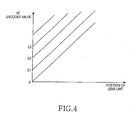
- a characteristic of the encoder initial value a graphical illustration of the position values of the lens unit in the VCM in which encoder initial values i.e., E1, E2 and E3 are mutually different is shown in FIG. 4 below.
- FIG. 4 illustrates a position value of the lens unit according to an encoder value on the auto focus process according to an exemplary embodiment of the present invention.
- the encoder initial values of each VCM of the driving unit are expressed in the order of E1, E2 and E3, respectively. This shows that the initial value may vary according to the individual variations of each respective VCM.
- the feedback control circuit 43 of the control unit 44 receives from the encoder 41 the value of the actual travel distance of the lens by each step, including the encoder initial value. After receiving the value of the actual travel distance, the feedback control circuit 43 compares, according to the corresponding steps, the AF encoder value received from the ISP 42 with the value of actual travel distance of the lens, generates a control signal for controlling the drive unit 40, and then linearizes the control signal by the addition and subtraction of actual travel distance of the lens on the basis of the AF encoder value received from the ISP 42. Such a linearized control signal is transmitted from the feedback control circuit 43 to the motor driver 45 of the control unit 44. After receiving, the motor driver 45 controls the driving unit 40 and linearly moves the position of the lens unit by each step, which is illustrated in FIG. 5 below.
- FIG. 5 illustrates a linear graph showing that a scaling factor of the position of the lens unit to an encoder value by each step is "1" in the auto focus camera according to an exemplary embodiment of the present invention.
- the VCM of the driving unit 40 performs an AF by moving the position of a lens.
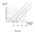
- the process of performing the AF according to the encoder value by each step based on the present invention is shown in the graphs of FIGs. 6A and 6B below.
- FIGs. 6A and 6B illustrates graphs showing a time required for the auto focus by using an initial value of the encoder according to respective first and second embodiments of the present invention.
- the AF is performed only by the minimum numbers of AF step in FIG. 6A and 6B .
- an encoder initial value of the driving unit is E1. Since the encoder initial value of the corresponding driving unit can be known before starting AF, the encoder value of the first AF step is set to E1. As a result, the position of a carrier is 0 as illustrated in the graph. That is, the driving unit does not drive until the encoder value becomes E1.
- the encoder value of the second AF step is set to E1+ ⁇ (i.e., the size of AF step) after the first AF step, the position of the carrier becomes ⁇ (i.e., tilt ⁇ ⁇ ).
- the encoder value of the third AF step is set to E1+2 ⁇ , the position of the carrier becomes 2 ⁇ .
- the encoder value of the AF step is increased by ⁇ , the position of the carrier moves as much as ⁇ .
- the initial value of the encoder of the driving unit is E2, unlike the encoder initial value of the driving unit in FIG. 6A .
- the encoder value of the first AF step is set to E2.
- the position of a carrier is 0 as illustrated in the graph. That is, the driving unit does not drive until the encoder value becomes E2.
- the encoder value of the second AF step is set to E2+ ⁇ (i.e., the size of AF step) after the first AF step, the position of the carrier becomes ⁇ (i.e., tilt ⁇ ⁇ ).
- the encoder value of the third AF step is set to E2+2 ⁇ , the position of the carrier becomes 2 ⁇ .
- the position of the carrier moves by as much as ⁇ .
- FIG. 7 illustrates a flowchart showing a process of performing the auto focus of the auto focus camera using the initial value of the encoder according to an exemplary embodiment of the present invention.
- step 701 the initial position of the lens unit is detected by using an encoder.
- the detected initial position value of the lens unit corresponds to an encoder initial value.
- step 703 the measured encoder initial value is matched to the initial position value of the lens unit, that is, a position where the lens unit starts to move for the first time.
- Step 703 prevents an unnecessary step by matching the encoder initial value to the starting point of the first AF step.
- the ISP adjusts the distance, which the lens unit will cover in progress of performing AF, by dividing the distance into sections corresponding to the preset number of steps by using the encoder initial value.
- the control unit moves the lens unit to the position corresponding to the encoder value of the corresponding step transmitted from the ISP.
- step 709 the control unit compares the value of the position where the lens unit is to supposed move according to the corresponding step with the value of the position where the lens unit actually has moved. If both the values are equal, the control unit proceeds to step 713 and detects the corresponding edge value. If not, the control unit proceeds to step 711 and readjusts the value of the position where the lens unit has actually moved, on the basis of the position value detected by the ISP, such that the encoder value detected by the ISP and the readjusted position value of the lens unit are equal, and then proceeds to step 713 and detects the corresponding edge value.
- step 715 the processes from step 707 to step 713 are repeatedly executed until all the edge values necessary for the AF are detected.
- the control unit proceeds to step 717 and performs the AF without generating the unnecessary step by determining the maximum edge value among the detected edge values.
- the AF steps are performed at a certain position irrespective of the different VCM driving current value according to the driving unit so that the AF driving time can be reduced.
- the present invention in an auto focus apparatus and method for a camera, it is possible to prevent the waste of auto focus steps by setting the starting point of the auto focus of the driving unit to "0" through use of the encoder initial value and by performing the first auto focus step at a certain position regardless of the different VCM driving current value according to the driving unit.
- At least one advantage is the ability set the minimum number of the auto focus steps. Accordingly, the present invention has an effect that it can reduce the auto focus driving time.
Landscapes
- Physics & Mathematics (AREA)
- General Physics & Mathematics (AREA)
- Engineering & Computer Science (AREA)
- Multimedia (AREA)
- Signal Processing (AREA)
- Optics & Photonics (AREA)
- Studio Devices (AREA)
- Lens Barrels (AREA)
Claims (15)
- Automatisches Fokussierungsverfahren in einer Kamera, wobei das Verfahren folgende Schritte umfasst:Erkennen durch einen Codierer eines Anfangswertes des Codierers, der einem Antriebsstromwert entspricht, der für eine Linseneinheit benötigt wird, damit sie damit beginnt, sich zum ersten Mal (701) zu bewegen, und Empfangen des Anfangswertes des Codierers durch einen Bildsignalprozessor, wobei der Anfangswert des Codierers einer der Codiererwerte ist, der einer Position entspricht, die gleich "0" ist, von der aus die Linseneinheit anfängt, sich zum ersten Mal zu bewegen, als Startpunkt eines Autofokusvorgangs (703), und jeder der Codiererwerte einem Positionswert entspricht, um den die Linseneinheit bewegt werden soll;Ausführen des Autofokusvorgangs durch Beginnen mit dem erkannten Anfangswert des Codierers und Teilen einer Strecke, über welche die Linseneinheit bewegt werden soll, in Abschnitte, die einer vorgegebenen Anzahl von Schritten (705) entsprechen;Vergleichen eines Positionswertes (709), um den die Linseneinheit in jedem Schritt der vorgegebenen Anzahl von Schritten bewegt werden soll, mit einem Positionswert, um den sich die Linseneinheit in jedem Schritt tatsächlich bewegt hat;Erkennen eines Randwertes (713), der eine Helligkeitsänderung für einen Umriss eines Motivs in jedem Schritt zeigt; undBeenden des Autofokusvorgangs (717) durch Bewegen der Linseneinheit in eine Position, die dem Randwert entspricht, der eine maximale Helligkeitsänderung für den Umriss des Motivs aufweist und aus den Randwerten ausgewählt wird, die für die vorgegebene Anzahl von Schritten erkannt wurden.
- Automatisches Fokussierungsverfahren nach Anspruch 1, wobei ein Hall-Sensor zum Messen der Anfangsposition der Linseneinheit durch den Codierer verwendet wird.
- Automatisches Fokussierungsverfahren nach Anspruch 2, wobei für eine Vielzahl von Linseneinheiten gemäß einer Blockierungsart und einer Blockierungsposition jeder jeweiligen Linseneinheit Anfangswerte des Codierers erkannt werden.
- Automatisches Fokussierungsverfahren nach Anspruch 1, wobei beim Abgleichen des gemessenen Anfangswertes des Codierers mit dem Anfangspositionswert, zu dem die Linseneinheit bewegt werden soll, kein Autofokusvorgang ausgeführt wird, bis ein Antriebsstromwert dem Anfangswert des Codierers entspricht.
- Automatisches Fokussierungsverfahren nach Anspruch 1, wobei beim Erkennen von Randwerten für so viele Schritte wie die Anzahl der vorgegebenen Anzahl von Schritten das Erkennen jedes Randwertes zum Einstellen des Positionswertes, um den sich die Linseneinheit während jedes Schritts der vorgegebenen Anzahl von Schritten tatsächlich bewegt hat, während der Ausführung in einer normalen Reihenfolge von einem ersten Schritt der vorgegebenen Anzahl ab linearisiert wird.
- Automatisches Fokussierungsverfahren nach Anspruch 5, wobei beim Einstellen des Positionswertes der zu linearisierenden Linseneinheit ein Randwert erkannt wird, indem die Position der Linseneinheit derart linear nachgestellt wird, dass ein Skalierungsfaktor des Positionswertes, um den sich die Linseneinheit bewegen soll, gemäß einem entsprechenden Schritt des Positionswertes, um den sich die Linseneinheit tatsächlich bewegt hat, gleich "1" ist.
- Autofokusgerät für eine Kamera, wobei das Gerät Folgendes umfasst:einen Codierer (340, 41) zum Erkennen eines Anfangswertes des Codierers, der einem Antriebsstrom entspricht, der für eine Linseneinheit (310) benötigt wird, damit sie damit beginnt, sich zum ersten Mal zu bewegen, wobei der Anfangswert des Codierers einer der Codiererwerte ist, der einer Position entspricht, die gleich "0" ist, von der aus die Linseneinheit anfängt, sich zum ersten Mal zu bewegen, als Startpunkt eines Autofokusvorgangs, und jeder der Codiererwerte einem Positionswert entspricht, um den die Linseneinheit bewegt werden soll;einen Bildsignalprozessor (350, 42) zum Empfangen des Anfangswertes des Codierers und zum gleichwertigen Einstellen einer Strecke, um die sich die Linseneinheit bewegen soll, durch Unterteilen der Strecke in eine gewisse Anzahl von Schritten während des Autofokusvorgangs; undeine Steuereinheit (370, 44) zum Vergleichen eines Positionswertes, um den die Linseneinheit in jedem Schritt bewegt werden soll, mit einem Positionswert, um den sich die Linseneinheit tatsächlich in jedem Schritt bewegt hat, wobei der Positionswert der Linseneinheit eingestellt wird, um den sich die Linseneinheit in jedem Schritt tatsächlich bewegt hat.
- Autofokusgerät nach Anspruch 7, wobei die Steuereinheit (370, 44) eine lineare Einstellung des Positionswertes vornimmt.
- Autofokusgerät nach Anspruch 7, wobei die Steuereinheit (370, 44) Folgendes umfasst:einen Rückkopplungs-Regelkreis zum linearen Nachstellen der Position der Linseneinheit, so dass ein Skalierungsfaktor des Positionswertes, um den sich die Linseneinheit bewegen soll, gemäß einem entsprechenden Schritt des Positionswertes, um den sich die Linseneinheit tatsächlich bewegt hat, gleich "1" ist; undeinen Antrieb (45) zum Bewegen der Linseneinheit durch Steuern eines Motors einer Antriebseinheit (330, 40), die den Positionswert der Linseneinheit empfängt, der durch den Rückkopplungs-Regelkreis nachgestellt wird, und die Linseneinheit bewegt.
- Autofokusgerät nach Anspruch 9, wobei die Antriebseinheit (330, 40) ferner einen Träger (334) umfasst, um die Linseneinheit entlang einer optischen Achse durch eine Antriebskraft des Motors (45) vor und zurück zu bewegen.
- Autofokusgerät nach Anspruch 7, wobei der Codierer (340, 41) einen Sensor umfasst, um eine Positionsänderung der Linseneinheit (310) zu erkennen.
- Autofokusgerät nach Anspruch 10, wobei der Codierer (340, 41) einen Hall-Sensor (342) und einen Magneten umfasst, wobei ein Magnet (344) an dem Träger der Antriebseinheit (330, 40) angebracht ist.
- Autofokusgerät nach Anspruch 7, wobei die Kamera Folgendes umfasst:eine Linseneinheit (310), die mindestens eine Linse (312) umfasst, um ein Bild eines Motivs zu formen;einen Bildsensor (320), um das Bild zu erkennen, das durch die Linseneinheit geformt wird, und um das erkannte Bild als elektrisches Signal bereitzustellen;einen Bildsignalprozessor (350, 42), um das Bildsignal zu verarbeiten, das von dem Bildsensor (320) Einzelbild für Einzelbild übertragen wird, und um das Bildsignal in mindestens eine vorherbestimmte Bildschirmcharakteristik umzuwandeln;eine Antriebseinheit (330, 40), um die Linseneinheit entlang der optischen Achse anzutreiben, wobei die Antriebseinheit einen Träger (334) umfasst; undeine Steuereinheit (370, 44), um die Antriebseinheit zu steuern.
- Autofokusgerät nach Anspruch 9, wobei der Rückkopplungs-Regelkreis (43) geeignet ist, um einen Wert von dem Codierer von einer tatsächlichen Bewegungsstrecke der Linseneinheit in jedem Schritt zu empfangen, wozu der Anfangswert des Codierers gehört, und wobei der Rückkopplungs-Regelkreis geeignet ist, um einen Codiererwert, der von dem Bildsignalprozessor (350, 42) empfangen wird, mit dem Wert der tatsächlichen Bewegungsstrecke der Linseneinheit (310) zu vergleichen, um ein Steuersignal zu generieren, um die Antriebseinheit zu steuern, und um das Steuersignal durch Addition und Subtraktion der tatsächlichen Bewegungsstrecke der Linseneinheit auf der Grundlage des Codiererwertes, der von dem Bildsignalprozessor empfangen wird, zu linearisieren.
- Autofokusgerät nach Anspruch 14, wobei das linearisierte Steuersignal, das von der Rückkopplungs-Regelschaltung (43) übertragen wird, einem Motorantrieb (45) der Steuereinheit (370, 44) bereitgestellt wird, um die Antriebseinheit zu steuern, indem die Position der Linseneinheit (310) in jedem Schritt linear bewegt wird.
Applications Claiming Priority (2)
| Application Number | Priority Date | Filing Date | Title |
|---|---|---|---|
| KR20070059886 | 2007-06-19 | ||
| KR1020070087650A KR101295433B1 (ko) | 2007-06-19 | 2007-08-30 | 카메라의 자동초점조절 장치 및 방법 |
Publications (2)
| Publication Number | Publication Date |
|---|---|
| EP2006733A1 EP2006733A1 (de) | 2008-12-24 |
| EP2006733B1 true EP2006733B1 (de) | 2013-05-22 |
Family
ID=39735323
Family Applications (1)
| Application Number | Title | Priority Date | Filing Date |
|---|---|---|---|
| EP08006315.9A Expired - Fee Related EP2006733B1 (de) | 2007-06-19 | 2008-03-31 | Autofokusvorrichtung und Verfahren für eine Kamera |
Country Status (2)
| Country | Link |
|---|---|
| US (1) | US8059956B2 (de) |
| EP (1) | EP2006733B1 (de) |
Cited By (2)
| Publication number | Priority date | Publication date | Assignee | Title |
|---|---|---|---|---|
| CN104301601A (zh) * | 2013-11-27 | 2015-01-21 | 中国航空工业集团公司洛阳电光设备研究所 | 一种粗精调结合的红外图像自动调焦方法 |
| US11805315B2 (en) | 2021-09-30 | 2023-10-31 | L3Harris Technologies, Inc. | Semi-transparent detector array for auto-focused nightvision systems |
Families Citing this family (10)
| Publication number | Priority date | Publication date | Assignee | Title |
|---|---|---|---|---|
| CN101603805B (zh) * | 2008-06-11 | 2012-05-16 | 鸿富锦精密工业(深圳)有限公司 | 测量系统 |
| KR100890590B1 (ko) * | 2008-10-02 | 2009-03-25 | 주식회사 세코닉스 | 카메라 모듈 및 그의 구동 방법 |
| CN101930150B (zh) * | 2009-06-18 | 2012-01-04 | 三洋电机株式会社 | 聚焦控制电路 |
| KR101137615B1 (ko) * | 2010-01-12 | 2012-04-19 | 삼성전자주식회사 | 디지털 카메라의 자동 초점 조정 방법 및 장치 |
| JP5609214B2 (ja) * | 2010-04-02 | 2014-10-22 | セイコーエプソン株式会社 | プロジェクターおよびその制御方法 |
| EP3260898B1 (de) | 2014-01-28 | 2021-09-15 | LG Innotek Co., Ltd. | Linsenbewegungseinheit und kameramodul damit |
| US9431887B2 (en) | 2014-06-06 | 2016-08-30 | Align Technology, Inc. | Lens positioning system |
| US10365121B2 (en) | 2015-02-06 | 2019-07-30 | Apple Inc. | Magnetic sensing for auto focus position detection |
| KR101912277B1 (ko) | 2015-11-23 | 2018-10-30 | 삼성전기 주식회사 | 액추에이터 구동 장치 및 이를 포함하는 카메라 모듈 |
| KR20210155695A (ko) | 2020-06-16 | 2021-12-23 | 삼성전자주식회사 | 화질 튜닝을 수행하는 이미지 처리 시스템 및 화질 튜닝 방법 |
Family Cites Families (15)
| Publication number | Priority date | Publication date | Assignee | Title |
|---|---|---|---|---|
| JP3581513B2 (ja) * | 1997-01-23 | 2004-10-27 | キヤノン株式会社 | 光学機器 |
| US5966550A (en) * | 1997-02-24 | 1999-10-12 | Asahi Kogaku Kogyo Kabushiki Kaisha | Automatic focusing apparatus in a camera |
| US6989865B1 (en) * | 1997-12-19 | 2006-01-24 | Canon Kabushiki Kaisha | Optical equipment and it control method, and computer-readable storage medium |
| JP4006082B2 (ja) * | 1998-03-20 | 2007-11-14 | キヤノン株式会社 | パルスモータ制御装置および方法、撮像装置 |
| JP3992992B2 (ja) * | 2002-02-19 | 2007-10-17 | 株式会社リコー | 被写体像取得装置 |
| JP2003333411A (ja) * | 2002-03-06 | 2003-11-21 | Canon Inc | 撮像装置、撮像方法、及び撮像制御コンピュータプログラム |
| US7391461B2 (en) | 2002-03-06 | 2008-06-24 | Canon Kabushiki Kaisha | Apparatus, method and control computer program for imaging a plurality of objects at different distances |
| JP2004048446A (ja) * | 2002-07-12 | 2004-02-12 | Fuji Photo Film Co Ltd | 自動焦点調節制御方法及び電子カメラ |
| US7355646B2 (en) * | 2003-03-27 | 2008-04-08 | Canon Kabushiki Kaisha | Drive control apparatus for driving magnification-varying lens unit to wide-angle end or telephoto end when switching from AF mode to MF mode |
| US7526192B2 (en) * | 2004-10-07 | 2009-04-28 | Hoya Corporation | Focus detection method and focus detection apparatus |
| US7929848B2 (en) * | 2006-02-14 | 2011-04-19 | Nikon Corporation | Vibration detection device, optical device, and method of operation of vibration detection device |
| US7773874B2 (en) * | 2006-06-05 | 2010-08-10 | Hoya Corporation | Focus detection method and focus detection device |
| KR20080081693A (ko) * | 2007-03-06 | 2008-09-10 | 삼성전자주식회사 | 카메라의 자동초점조절 방법 |
| KR101420425B1 (ko) * | 2007-09-03 | 2014-07-16 | 삼성전자주식회사 | 카메라의 자동 초점 조절 장치 및 방법 |
| US8084969B2 (en) * | 2007-10-01 | 2011-12-27 | Allegro Microsystems, Inc. | Hall-effect based linear motor controller |
-
2008
- 2008-03-31 EP EP08006315.9A patent/EP2006733B1/de not_active Expired - Fee Related
- 2008-05-20 US US12/123,563 patent/US8059956B2/en active Active
Cited By (3)
| Publication number | Priority date | Publication date | Assignee | Title |
|---|---|---|---|---|
| CN104301601A (zh) * | 2013-11-27 | 2015-01-21 | 中国航空工业集团公司洛阳电光设备研究所 | 一种粗精调结合的红外图像自动调焦方法 |
| CN104301601B (zh) * | 2013-11-27 | 2017-11-03 | 中国航空工业集团公司洛阳电光设备研究所 | 一种粗精调结合的红外图像自动调焦方法 |
| US11805315B2 (en) | 2021-09-30 | 2023-10-31 | L3Harris Technologies, Inc. | Semi-transparent detector array for auto-focused nightvision systems |
Also Published As
| Publication number | Publication date |
|---|---|
| US20080317452A1 (en) | 2008-12-25 |
| US8059956B2 (en) | 2011-11-15 |
| EP2006733A1 (de) | 2008-12-24 |
Similar Documents
| Publication | Publication Date | Title |
|---|---|---|
| EP2006733B1 (de) | Autofokusvorrichtung und Verfahren für eine Kamera | |
| KR101295433B1 (ko) | 카메라의 자동초점조절 장치 및 방법 | |
| EP2031442B1 (de) | Autofokusvorrichtung und Verfahren für eine Kamera | |
| JP3992992B2 (ja) | 被写体像取得装置 | |
| US7469098B2 (en) | Optical apparatus | |
| US7831138B2 (en) | Focus adjusting method and focus adjusting device | |
| JP4582152B2 (ja) | 撮像装置、および撮像装置制御方法、並びにコンピュータ・プログラム | |
| US7450836B2 (en) | Image device, control method for the imaging device, program for performing the control method, and recording medium recording the program | |
| JP5380784B2 (ja) | オートフォーカス装置、撮像装置及びオートフォーカス方法 | |
| US20080219655A1 (en) | Autofocus method for a camera | |
| US20100067890A1 (en) | Autofocus apparatus and method for controlling the same | |
| US8564713B2 (en) | Image pickup apparatus that makes movement of focus lens inconspicuous, and control method for the image pickup apparatus | |
| JP2728316B2 (ja) | レンズ位置制御装置を有する光学機器 | |
| US9900493B2 (en) | Focus detecting apparatus, and method of prediction for the same | |
| JP6727453B2 (ja) | 撮像装置、撮像装置の制御方法、及び撮像装置の制御プログラム | |
| US8154624B2 (en) | Image pickup apparatus and control method thereof | |
| US7411624B2 (en) | Image sensing apparatus, control method therefor, program, and storage medium | |
| JP2006208703A (ja) | 電子カメラ | |
| JP2000009982A (ja) | 撮影レンズの組立時ピント調整方法 | |
| JPWO2019064759A1 (ja) | 撮像装置、撮像方法、及びプログラム | |
| US20080024648A1 (en) | Image-pickup apparatus and focus control method | |
| JP4779383B2 (ja) | デジタルカメラ | |
| JP2006011035A (ja) | 自動合焦装置、撮像装置及び合焦位置検出方法 | |
| JP5574634B2 (ja) | 撮像装置及びその制御方法 | |
| JP2004177476A (ja) | カメラ |
Legal Events
| Date | Code | Title | Description |
|---|---|---|---|
| PUAI | Public reference made under article 153(3) epc to a published international application that has entered the european phase |
Free format text: ORIGINAL CODE: 0009012 |
|
| 17P | Request for examination filed |
Effective date: 20080331 |
|
| AK | Designated contracting states |
Kind code of ref document: A1 Designated state(s): AT BE BG CH CY CZ DE DK EE ES FI FR GB GR HR HU IE IS IT LI LT LU LV MC MT NL NO PL PT RO SE SI SK TR |
|
| AX | Request for extension of the european patent |
Extension state: AL BA MK RS |
|
| 17Q | First examination report despatched |
Effective date: 20090724 |
|
| AKX | Designation fees paid |
Designated state(s): DE FR GB |
|
| RAP1 | Party data changed (applicant data changed or rights of an application transferred) |
Owner name: SAMSUNG ELECTRONICS CO., LTD. |
|
| GRAP | Despatch of communication of intention to grant a patent |
Free format text: ORIGINAL CODE: EPIDOSNIGR1 |
|
| GRAS | Grant fee paid |
Free format text: ORIGINAL CODE: EPIDOSNIGR3 |
|
| GRAA | (expected) grant |
Free format text: ORIGINAL CODE: 0009210 |
|
| AK | Designated contracting states |
Kind code of ref document: B1 Designated state(s): DE FR GB |
|
| REG | Reference to a national code |
Ref country code: GB Ref legal event code: FG4D |
|
| REG | Reference to a national code |
Ref country code: DE Ref legal event code: R096 Ref document number: 602008024680 Country of ref document: DE Effective date: 20130718 |
|
| PLBE | No opposition filed within time limit |
Free format text: ORIGINAL CODE: 0009261 |
|
| STAA | Information on the status of an ep patent application or granted ep patent |
Free format text: STATUS: NO OPPOSITION FILED WITHIN TIME LIMIT |
|
| 26N | No opposition filed |
Effective date: 20140225 |
|
| REG | Reference to a national code |
Ref country code: DE Ref legal event code: R097 Ref document number: 602008024680 Country of ref document: DE Effective date: 20140225 |
|
| REG | Reference to a national code |
Ref country code: FR Ref legal event code: PLFP Year of fee payment: 9 |
|
| REG | Reference to a national code |
Ref country code: FR Ref legal event code: PLFP Year of fee payment: 10 |
|
| REG | Reference to a national code |
Ref country code: FR Ref legal event code: PLFP Year of fee payment: 11 |
|
| PGFP | Annual fee paid to national office [announced via postgrant information from national office to epo] |
Ref country code: DE Payment date: 20190220 Year of fee payment: 12 |
|
| PGFP | Annual fee paid to national office [announced via postgrant information from national office to epo] |
Ref country code: FR Payment date: 20190225 Year of fee payment: 12 |
|
| PGFP | Annual fee paid to national office [announced via postgrant information from national office to epo] |
Ref country code: GB Payment date: 20200225 Year of fee payment: 13 |
|
| REG | Reference to a national code |
Ref country code: DE Ref legal event code: R119 Ref document number: 602008024680 Country of ref document: DE |
|
| PG25 | Lapsed in a contracting state [announced via postgrant information from national office to epo] |
Ref country code: FR Free format text: LAPSE BECAUSE OF NON-PAYMENT OF DUE FEES Effective date: 20200331 Ref country code: DE Free format text: LAPSE BECAUSE OF NON-PAYMENT OF DUE FEES Effective date: 20201001 |
|
| GBPC | Gb: european patent ceased through non-payment of renewal fee |
Effective date: 20210331 |
|
| PG25 | Lapsed in a contracting state [announced via postgrant information from national office to epo] |
Ref country code: GB Free format text: LAPSE BECAUSE OF NON-PAYMENT OF DUE FEES Effective date: 20210331 |