EP2006256A1 - Quartz glass made burner - Google Patents
Quartz glass made burner Download PDFInfo
- Publication number
- EP2006256A1 EP2006256A1 EP07737559A EP07737559A EP2006256A1 EP 2006256 A1 EP2006256 A1 EP 2006256A1 EP 07737559 A EP07737559 A EP 07737559A EP 07737559 A EP07737559 A EP 07737559A EP 2006256 A1 EP2006256 A1 EP 2006256A1
- Authority
- EP
- European Patent Office
- Prior art keywords
- outer tube
- quartz glass
- burner
- tip
- inner diameter
- Prior art date
- Legal status (The legal status is an assumption and is not a legal conclusion. Google has not performed a legal analysis and makes no representation as to the accuracy of the status listed.)
- Granted
Links
Images
Classifications
-
- C—CHEMISTRY; METALLURGY
- C03—GLASS; MINERAL OR SLAG WOOL
- C03B—MANUFACTURE, SHAPING, OR SUPPLEMENTARY PROCESSES
- C03B19/00—Other methods of shaping glass
- C03B19/14—Other methods of shaping glass by gas- or vapour- phase reaction processes
-
- F—MECHANICAL ENGINEERING; LIGHTING; HEATING; WEAPONS; BLASTING
- F23—COMBUSTION APPARATUS; COMBUSTION PROCESSES
- F23D—BURNERS
- F23D14/00—Burners for combustion of a gas, e.g. of a gas stored under pressure as a liquid
- F23D14/20—Non-premix gas burners, i.e. in which gaseous fuel is mixed with combustion air on arrival at the combustion zone
- F23D14/22—Non-premix gas burners, i.e. in which gaseous fuel is mixed with combustion air on arrival at the combustion zone with separate air and gas feed ducts, e.g. with ducts running parallel or crossing each other
-
- C—CHEMISTRY; METALLURGY
- C03—GLASS; MINERAL OR SLAG WOOL
- C03B—MANUFACTURE, SHAPING, OR SUPPLEMENTARY PROCESSES
- C03B19/00—Other methods of shaping glass
- C03B19/14—Other methods of shaping glass by gas- or vapour- phase reaction processes
- C03B19/1415—Reactant delivery systems
- C03B19/1423—Reactant deposition burners
-
- C—CHEMISTRY; METALLURGY
- C03—GLASS; MINERAL OR SLAG WOOL
- C03B—MANUFACTURE, SHAPING, OR SUPPLEMENTARY PROCESSES
- C03B2207/00—Glass deposition burners
- C03B2207/04—Multi-nested ports
- C03B2207/12—Nozzle or orifice plates
-
- C—CHEMISTRY; METALLURGY
- C03—GLASS; MINERAL OR SLAG WOOL
- C03B—MANUFACTURE, SHAPING, OR SUPPLEMENTARY PROCESSES
- C03B2207/00—Glass deposition burners
- C03B2207/04—Multi-nested ports
- C03B2207/14—Tapered or flared nozzles or ports angled to central burner axis
Definitions
- the present invention relates to a quartz glass burner.
- the present invention relates to a quartz glass burner suitable for use in flame working, manufacturing of synthetic quartz glass, and the like.
- the present application claims priority from a Japanese Patent Application No. 2006-053215 filed on February 28, 2006 , the contents of which are incorporated herein by reference, if applicable.
- a quartz glass burner can achieve high temperatures by feeding a supporting gas from an inner tube nozzle into an outer tube containing a combustible gas to ignite the combustible gas, and is therefore used for various types of flame working.
- a gas containing pieces of glass is fed through any of the tubules to achieve flame hydrolysis, thereby synthesizing the quartz glass microparticles.
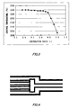
- Fig. 4 shows a conventional quartz glass burner.
- the quartz glass burner is provided with a quartz glass outer tube, a tubule branching portion, and a multibranched-tube quartz glass nozzle that is positioned on an inner side of an outer tube and that houses a plurality of tubules formed continuously along the tubule branching portion.
- Patent Document 1 designates the positioning and number of nozzles in order to enhance the glass microparticle synthesizing efficiency and deposition efficiency.
- Patent Document 2 the diameter and speed of the nozzle is designated.
- a quartz glass burner characterized by having a multibranched-tube quartz glass nozzle made up of multiple tubules housed in a quartz glass outer tube, and by having an inner diameter of the outer tube contracted such that an inner diameter of a tip of the outer tube is between 0.65 and 0.90 times the inner diameter of a trunk of the outer tube.
- the nozzle is structured such that a region from a tubule branching portion to a tip of the nozzle is housed in the outer tube, and that the outer tube housing the tubules has a length that is greater than or equal to 1.5 times the inner diameter of the tip of the outer tube.
- the quartz glass burner of the present invention decreases the temperature irregularity of the flame working and the deposition body surface by causing the flow velocity distribution of the combustible gas to be uniform at the tip of the outer tube of the burner. Decreasing the temperature irregularity in this way yields favorable results, such as enhancement of the firepower during flame working and enhancement of the glass microparticle deposition efficiency.
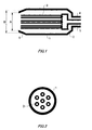
- Fig. 1 is a schematic cross-sectional view taken along a vertical axis of the burner showing an exemplary quartz glass burner of the present invention.
- Fig, 2 is a horizontal cross-sectional view showing the quartz glass burner of Fig. 1 .
- the quartz glass burner is designed for flame working of synthetic quartz glass.
- An outer tube 1 of the quartz glass burner houses a multibranched-tube nozzle 3, which is made up of a plurality of tubules mounted on a tubule branching portion 2.
- a hydrogen gas injector 4 that injects hydrogen gas, serving as the combustible gas, is connected to the outer tube 1.
- This burner can be used as a burner for synthesizing/depositing glass microparticles by connecting a glass injecting tube, not shown, to any of the tubules.
- the inner diameter of the outer tube 1 decreases gradually from B to A beginning at the contracted portion 6 at the tip. More specifically, the inner diameter of the outer tube tip is decreased to be between 0.65 and 0.90 times the inner diameter of the trunk of the outer tube.
- this contraction ratio is greater than 0.90, the flow velocity distribution is not uniform at the tip of the outer tube because sufficient pressure is not applied during the ejection of the gas, thereby causing a decrease in the flame working efficiency.
- the quartz glass burner is configured to be able to supply glass to any one of the tubules in order to synthesize the glass microparticles, the temperature of the deposition surface decreases, thereby decreasing the adhesive efficiency of the synthesized glass microparticles.
- the contraction ratio is less than 0.65, a greater enhancement of flame working efficiency and adhesion efficiency is not achieved since sufficient pressure is already being applied, and also the outer diameter of the outer tube is enlarged and therefore requires a larger space than allowed by the apparatus.
- Contracting the tip of the outer tube in this way enables sufficient pressure to be applied at the contracted portion, even if the tip of the outer tube is enlarged.
- the flow velocity distribution of the combustible gas is uniform at the tip of the outer tube, thereby decreasing the temperature irregularity of the flame working surface and the deposition surface.
- the decrease in the temperature irregularity results in enhanced firepower during flame working and enhanced glass microparticle deposition efficiency.
- a more uniform flow velocity distribution can be achieved by setting the length of the outer tube to be greater than or equal to 1.5 times the diameter of the tip of the outer tube.
- one nozzle is disposed in the center of the outer tube for the supporting gas, this nozzle is surrounded with six other nozzles, and the inner diameter of the tip of the outer tube to be 25mm ⁇ .
- Quartz glass burners were manufactured with the above specifications and a large variety of contraction ratios by changing the inner diameter of the trunk of the outer tube.
- quartz glass burners having differing contraction ratios were used for flame working of a quartz glass rod having an outer diameter of 60mm ⁇ .
- Each of the seven tubules forming the nozzle may be disposed parallel to the central axis of the burner or mounted in the outer tube in a manner to come together at a focal point at a desired position lengthwise on the central axis.
- the quartz glass burner of the present invention is beneficial when used for flame working or manufacturing of synthetic quartz glass, and provides low manufacturing costs and enhanced quality.
Landscapes
- Engineering & Computer Science (AREA)
- Chemical & Material Sciences (AREA)
- Combustion & Propulsion (AREA)
- Mechanical Engineering (AREA)
- General Engineering & Computer Science (AREA)
- Chemical Kinetics & Catalysis (AREA)
- Manufacturing & Machinery (AREA)
- Materials Engineering (AREA)
- Organic Chemistry (AREA)
- Glass Melting And Manufacturing (AREA)
- Gas Burners (AREA)
- Manufacture, Treatment Of Glass Fibers (AREA)
Abstract
Description
- The present invention relates to a quartz glass burner. In particular, the present invention relates to a quartz glass burner suitable for use in flame working, manufacturing of synthetic quartz glass, and the like. The present application claims priority from a Japanese Patent Application No.
2006-053215 filed on February 28, 2006 - A quartz glass burner can achieve high temperatures by feeding a supporting gas from an inner tube nozzle into an outer tube containing a combustible gas to ignite the combustible gas, and is therefore used for various types of flame working. When using a burner in which a plurality of tubules serving as nozzles are inserted throughout the outer tube, in addition to feeding a supporting gas from an inner tube nozzle into an outer tube containing a combustible gas to ignite the combustible gas, a gas containing pieces of glass is fed through any of the tubules to achieve flame hydrolysis, thereby synthesizing the quartz glass microparticles.
-
Fig. 4 shows a conventional quartz glass burner. InFig. 4 , the quartz glass burner is provided with a quartz glass outer tube, a tubule branching portion, and a multibranched-tube quartz glass nozzle that is positioned on an inner side of an outer tube and that houses a plurality of tubules formed continuously along the tubule branching portion. - Conventionally, the positioning and number of nozzles feeding the supporting gas in this type of quartz glass burner is considered in an attempt to enhance the firepower during flame working and increase the glass microparticle deposition efficiency.
- For example, Patent Document 1 designates the positioning and number of nozzles in order to enhance the glass microparticle synthesizing efficiency and deposition efficiency. In
Patent Document 2, the diameter and speed of the nozzle is designated. - However, optimizing the supply of gas from the nozzles is not the only way to enhance the flame working efficiency and the deposition efficiency. It is also important to optimize the supply of gas from the outer tube. A flow velocity distribution often occurs in the supply of gas from the outer tube due to the large area through which the gas flows, such that the flow velocity at the tip of the burner is uneven. This causes a temperature irregularity, which decreases the flame working efficiency and the deposition efficiency. This temperature irregularity is especially prominent when enlarging the diameter of the outer tube to enlarge the flame.
Patent Document 1: Japanese Patent Application Publication No.2003-206154
Patent Document 2: Japanese Patent Application Publication No.2003-165737 - It is an object of the present invention to provide a quartz glass burner that enhances the firepower during flame working and increases the glass microparticle deposition efficiency by causing the flow velocity distribution of the gas supplied from the outer tube to be uniform at the tip of the burner.
- So as to solve the above-described problems, as a first embodiment of the present invention, provided is a quartz glass burner characterized by having a multibranched-tube quartz glass nozzle made up of multiple tubules housed in a quartz glass outer tube, and by having an inner diameter of the outer tube contracted such that an inner diameter of a tip of the outer tube is between 0.65 and 0.90 times the inner diameter of a trunk of the outer tube.
- It is desirable that the nozzle is structured such that a region from a tubule branching portion to a tip of the nozzle is housed in the outer tube, and that the outer tube housing the tubules has a length that is greater than or equal to 1.5 times the inner diameter of the tip of the outer tube.
- The summary clause does not necessarily describe all necessary features of the embodiments of the present invention. The present invention may also be a sub-combination of the features described above.
- The quartz glass burner of the present invention decreases the temperature irregularity of the flame working and the deposition body surface by causing the flow velocity distribution of the combustible gas to be uniform at the tip of the outer tube of the burner. Decreasing the temperature irregularity in this way yields favorable results, such as enhancement of the firepower during flame working and enhancement of the glass microparticle deposition efficiency.
-
-
Fig. 1 is a schematic cross-sectional view taken along a vertical axis of the burner showing an exemplary quartz glass burner of the present invention. -
Fig. 2 is a horizontal cross-sectional view showing the quartz glass burner ofFig. 1 . -
Fig. 3 is a graph showing a relation between contraction ratios of various burners and the maximum surface temperatures of heated quartz glass rods. -
Fig. 4 is a horizontal cross-sectional view taken along a vertical axis of the burner showing a conventional quartz glass burner. - As follows, an aspect of the present invention is described by embodiments. The following embodiments do not limit the invention that relates to the claims and not all combinations of the features described in the embodiments are necessarily essential to means for solving the problems of the invention.
-
Fig. 1 is a schematic cross-sectional view taken along a vertical axis of the burner showing an exemplary quartz glass burner of the present invention.Fig, 2 is a horizontal cross-sectional view showing the quartz glass burner ofFig. 1 . - The quartz glass burner is designed for flame working of synthetic quartz glass. An outer tube 1 of the quartz glass burner houses a multibranched-
tube nozzle 3, which is made up of a plurality of tubules mounted on atubule branching portion 2. A hydrogen gas injector 4 that injects hydrogen gas, serving as the combustible gas, is connected to the outer tube 1. Anoxygen gas injector 5 that injects oxygen gas, serving as the supporting gas, is connected to thetubule branching portion 2 on which the plurality of tubules are mounted. - This burner can be used as a burner for synthesizing/depositing glass microparticles by connecting a glass injecting tube, not shown, to any of the tubules.
- As shown in
Fig. 1 , the inner diameter of the outer tube 1 decreases gradually from B to A beginning at the contractedportion 6 at the tip. More specifically, the inner diameter of the outer tube tip is decreased to be between 0.65 and 0.90 times the inner diameter of the trunk of the outer tube. - If this contraction ratio is greater than 0.90, the flow velocity distribution is not uniform at the tip of the outer tube because sufficient pressure is not applied during the ejection of the gas, thereby causing a decrease in the flame working efficiency. If the quartz glass burner is configured to be able to supply glass to any one of the tubules in order to synthesize the glass microparticles, the temperature of the deposition surface decreases, thereby decreasing the adhesive efficiency of the synthesized glass microparticles. If the contraction ratio is less than 0.65, a greater enhancement of flame working efficiency and adhesion efficiency is not achieved since sufficient pressure is already being applied, and also the outer diameter of the outer tube is enlarged and therefore requires a larger space than allowed by the apparatus.
- Contracting the tip of the outer tube in this way enables sufficient pressure to be applied at the contracted portion, even if the tip of the outer tube is enlarged. As a result, the flow velocity distribution of the combustible gas is uniform at the tip of the outer tube, thereby decreasing the temperature irregularity of the flame working surface and the deposition surface. The decrease in the temperature irregularity results in enhanced firepower during flame working and enhanced glass microparticle deposition efficiency.
Furthermore, a more uniform flow velocity distribution can be achieved by setting the length of the outer tube to be greater than or equal to 1.5 times the diameter of the tip of the outer tube. - As shown in
Fig. 2 , one nozzle is disposed in the center of the outer tube for the supporting gas, this nozzle is surrounded with six other nozzles, and the inner diameter of the tip of the outer tube to be 25mmϕ. Quartz glass burners were manufactured with the above specifications and a large variety of contraction ratios by changing the inner diameter of the trunk of the outer tube. - These quartz glass burners having differing contraction ratios were used for flame working of a quartz glass rod having an outer diameter of 60mmϕ. Each of the seven tubules forming the nozzle may be disposed parallel to the central axis of the burner or mounted in the outer tube in a manner to come together at a focal point at a desired position lengthwise on the central axis.
- While measuring the surface temperature of a flame working section of each of the burners with a radiation thermometer, the amounts of the gases fed through the outer tube and the nozzle was changed for each burner to achieve the maximum surface temperature. The resulting relation between the contraction ratios and the maximum temperatures is shown in
Fig. 3 . - As shown in
Fig. 3 , when the contraction ratio A/B is greater than 0.90, the surface temperature decreases, which also decreases the thermal efficiency. This drop occurs because insufficient contraction results in a large flow velocity distribution of the combustible gas at the tip of the outer tube. On the other hand, when the contraction ratio is less than or equal to 0.65, greater efficiency is not expected since there is already sufficient contraction. Furthermore, when the contraction ratio is 0.65 and the internal diameter of the tip contracted portion is set to 25mmϕ, the inner diameter of the trunk of the outer tube becomes 38mmϕ, which is undesirable as it requires a space greater than the apparatus can allow. - While the embodiments of the present invention have been described, the technical scope of the invention is not limited to the above described embodiments. It is apparent to persons skilled in the art that various alterations and improvements can be added to the above-described embodiments. It is also apparent from the scope of the claims that the embodiments added with such alterations or improvements can be included in the technical scope of the invention.
- The quartz glass burner of the present invention is beneficial when used for flame working or manufacturing of synthetic quartz glass, and provides low manufacturing costs and enhanced quality.
Claims (3)
- A quartz glass burner comprising a multibranched-tube quartz glass nozzle made up of multiple tubules housed in a quartz glass outer tube, wherein
an inner diameter of the outer tube contracted such that an inner diameter of a tip of the outer tube is between 0.65 and 0.90 times the inner diameter of a trunk of the outer tube. - The quartz glass burner according to Claim 1, wherein
the nozzle is structured such that a region from a tubule branching portion to a tip of the nozzle is housed in the outer tube. - The quartz glass burner according to any one of Claim 1 and Claim 2, wherein
the outer tube housing the tubules has a length that is greater than or equal to 1.5 times the inner diameter of the tip of the outer tube.
Applications Claiming Priority (2)
| Application Number | Priority Date | Filing Date | Title |
|---|---|---|---|
| JP2006053215A JP5036193B2 (en) | 2006-02-28 | 2006-02-28 | Flame adjustment method for quartz glass burner |
| PCT/JP2007/053841 WO2007100019A1 (en) | 2006-02-28 | 2007-02-28 | Quartz glass made burner |
Publications (3)
| Publication Number | Publication Date |
|---|---|
| EP2006256A1 true EP2006256A1 (en) | 2008-12-24 |
| EP2006256A4 EP2006256A4 (en) | 2012-07-11 |
| EP2006256B1 EP2006256B1 (en) | 2016-10-19 |
Family
ID=38459120
Family Applications (1)
| Application Number | Title | Priority Date | Filing Date |
|---|---|---|---|
| EP07737559.0A Ceased EP2006256B1 (en) | 2006-02-28 | 2007-02-28 | Quartz glass made burner |
Country Status (6)
| Country | Link |
|---|---|
| US (1) | US20090068605A1 (en) |
| EP (1) | EP2006256B1 (en) |
| JP (1) | JP5036193B2 (en) |
| KR (1) | KR100979867B1 (en) |
| CN (2) | CN101426738A (en) |
| WO (1) | WO2007100019A1 (en) |
Families Citing this family (9)
| Publication number | Priority date | Publication date | Assignee | Title |
|---|---|---|---|---|
| KR101036064B1 (en) | 2008-02-27 | 2011-05-19 | 신에쓰 가가꾸 고교 가부시끼가이샤 | Burner for manufacturing porous glass base material |
| JP5234672B2 (en) * | 2010-09-24 | 2013-07-10 | 信越化学工業株式会社 | Quartz glass burner |
| CN103842303B (en) | 2011-09-29 | 2018-07-03 | 住友电气工业株式会社 | The manufacturing method of glass microbead deposit and gas preform |
| JP5682577B2 (en) * | 2011-09-29 | 2015-03-11 | 住友電気工業株式会社 | Fine glass particle deposit and method for producing glass matrix |
| KR101659339B1 (en) * | 2014-04-18 | 2016-09-23 | (주) 디에스테크노 | The burner for manufacturing quartz glass ingot |
| KR101718915B1 (en) | 2015-04-03 | 2017-03-24 | (주) 디에스테크노 | Multi burner for manufacturing quartz glass ingot |
| CN107448941A (en) * | 2017-09-12 | 2017-12-08 | 河北明亮玻璃制品有限公司 | The combustion-supporting lamp blown glass processing bank light of binary air intake |
| JP6979915B2 (en) * | 2018-03-29 | 2021-12-15 | 古河電気工業株式会社 | Optical fiber porous base material manufacturing equipment and optical fiber porous base material manufacturing method |
| CN113666613A (en) * | 2021-08-21 | 2021-11-19 | 江苏圣君纳米科技有限公司 | Metal high-temperature fire head |
Family Cites Families (26)
| Publication number | Priority date | Publication date | Assignee | Title |
|---|---|---|---|---|
| US2911035A (en) * | 1956-12-05 | 1959-11-03 | Bethlehem Apparatus Company In | Polymix gas burner |
| NL285334A (en) * | 1962-01-13 | 1900-01-01 | ||
| US3856457A (en) * | 1972-12-29 | 1974-12-24 | Air Prod & Chem | Burner of the oxy-fuel type |
| JPH0729795B2 (en) * | 1987-04-30 | 1995-04-05 | 信越化学工業株式会社 | Quartz glass burner |
| JPS6467519A (en) * | 1987-09-08 | 1989-03-14 | Shinetsu Sekiei Yamagata | Burner made of quartz glass |
| JPH04209725A (en) * | 1990-11-30 | 1992-07-31 | Toshiba Ceramics Co Ltd | Burner device |
| JPH04209730A (en) * | 1990-11-30 | 1992-07-31 | Fujikura Ltd | Production of preform of optical fiber |
| US5120582A (en) * | 1991-01-16 | 1992-06-09 | Browning James A | Maximum combustion energy conversion air fuel internal burner |
| JPH05105471A (en) * | 1991-10-11 | 1993-04-27 | Fujikura Ltd | Optical fiber base material manufacturing method |
| JP3182222B2 (en) * | 1992-08-17 | 2001-07-03 | 東芝セラミックス株式会社 | Quartz glass burner |
| JPH07232929A (en) * | 1994-02-22 | 1995-09-05 | Sumitomo Electric Ind Ltd | Oxyhydrogen burner for glass processing |
| US5516281A (en) * | 1995-02-06 | 1996-05-14 | Molodow; Marvin A. | Multiple jet burner |
| JP3045719B1 (en) * | 1999-02-01 | 2000-05-29 | 信越化学工業株式会社 | Optical fiber preform burner |
| JP3714823B2 (en) * | 1999-04-27 | 2005-11-09 | 信越化学工業株式会社 | Burner for optical fiber preform processing |
| JP2001342026A (en) * | 2000-05-30 | 2001-12-11 | Tosoh Quartz Corp | Method and apparatus of manufacturing quartz glass |
| JP4388206B2 (en) * | 2000-06-28 | 2009-12-24 | 東ソー・クォーツ株式会社 | Burner for manufacturing fused silica glass |
| JP2002228121A (en) * | 2001-01-31 | 2002-08-14 | Toshiba Ceramics Co Ltd | Method and apparatus for manufacturing nozzle for quartz glass burner |
| JP2002356332A (en) * | 2001-05-31 | 2002-12-13 | Toshiba Ceramics Co Ltd | Quartz glass burner, method of manufacturing the same, and inner diameter measuring jig used therein |
| JP4043768B2 (en) | 2001-11-27 | 2008-02-06 | 古河電気工業株式会社 | Manufacturing method of optical fiber preform |
| JP3881985B2 (en) * | 2001-12-04 | 2007-02-14 | 株式会社アトック | Quartz glass fluid single-hole nozzle and quartz glass fluid multi-hole burner head |
| JP2003206154A (en) | 2002-01-15 | 2003-07-22 | Fujikura Ltd | Burner device for producing optical fiber porous preform and method for producing optical fiber porous preform using the same |
| JP3640071B2 (en) * | 2002-06-28 | 2005-04-20 | 株式会社 旭セミコン | Quartz burner equipment |
| JP2004203670A (en) * | 2002-12-25 | 2004-07-22 | Shin Etsu Chem Co Ltd | Processing method of preform for optical fiber and apparatus used for the method |
| JP4220809B2 (en) * | 2003-03-11 | 2009-02-04 | 株式会社フジクラ | Burner for synthesizing glass fine particles and method for producing porous preform for optical fiber |
| JP2006053215A (en) | 2004-08-10 | 2006-02-23 | Konica Minolta Photo Imaging Inc | Development processing apparatus and maintenance system for silver halide photographic material |
| JP4645972B2 (en) * | 2005-12-14 | 2011-03-09 | 修 廣田 | Injection flame burner and furnace, and flame generation method |
-
2006
- 2006-02-28 JP JP2006053215A patent/JP5036193B2/en not_active Expired - Fee Related
-
2007
- 2007-02-28 CN CNA2007800138217A patent/CN101426738A/en active Pending
- 2007-02-28 EP EP07737559.0A patent/EP2006256B1/en not_active Ceased
- 2007-02-28 KR KR1020087021301A patent/KR100979867B1/en not_active Expired - Fee Related
- 2007-02-28 CN CN201410549826.3A patent/CN104445874A/en active Pending
- 2007-02-28 WO PCT/JP2007/053841 patent/WO2007100019A1/en not_active Ceased
-
2008
- 2008-08-27 US US12/199,597 patent/US20090068605A1/en not_active Abandoned
Also Published As
| Publication number | Publication date |
|---|---|
| KR100979867B1 (en) | 2010-09-02 |
| EP2006256B1 (en) | 2016-10-19 |
| CN104445874A (en) | 2015-03-25 |
| KR20080098402A (en) | 2008-11-07 |
| CN101426738A (en) | 2009-05-06 |
| WO2007100019A1 (en) | 2007-09-07 |
| JP2007230813A (en) | 2007-09-13 |
| US20090068605A1 (en) | 2009-03-12 |
| EP2006256A4 (en) | 2012-07-11 |
| JP5036193B2 (en) | 2012-09-26 |
Similar Documents
| Publication | Publication Date | Title |
|---|---|---|
| EP2006256B1 (en) | Quartz glass made burner | |
| KR101168494B1 (en) | Gas turbine combustor | |
| CN101965316B (en) | Burner for manufacturing porous glass base material | |
| US9032761B2 (en) | Porous glass matrix producing burner and porous glass matrix producing method | |
| CN102234178B (en) | For the manufacture of the burner of porous glass preform | |
| EP2249082B1 (en) | Combustion heater | |
| EP2244012A1 (en) | Combustion heater | |
| CN209604175U (en) | engine and casing thereof | |
| US8402788B2 (en) | Method for manufacturing optical fiber base material | |
| JP4845221B2 (en) | Method for producing porous glass base material | |
| EP2221281A2 (en) | Burner for manufacturing porous glass base material, and manufacturing method of porous glass base material | |
| JP2012066998A (en) | Burner for glass fine particle synthesis and manufacturing method for glass fine particle deposited body | |
| JP5234672B2 (en) | Quartz glass burner | |
| KR101036064B1 (en) | Burner for manufacturing porous glass base material | |
| JP5359573B2 (en) | Multi-tube burner manufacturing method and multi-tube burner | |
| GB2092738A (en) | Burner for the production of preforms for optical fibres | |
| JP5485003B2 (en) | Optical fiber preform manufacturing method | |
| US8459063B2 (en) | Burner for producing porous glass preform | |
| EP1736448A1 (en) | Manufacturing apparatus for porous glass preform and glass preform for optical fiber | |
| KR20060024447A (en) | Manufacturing method of optical fiber base material | |
| JPH09132415A (en) | Torch for synthesizing glass particles | |
| US8312744B2 (en) | Burner for producing glass fine particles and method for manufacturing porous glass base material using the same | |
| CN110966607B (en) | Natural gas auxiliary flame treatment burner |
Legal Events
| Date | Code | Title | Description |
|---|---|---|---|
| PUAI | Public reference made under article 153(3) epc to a published international application that has entered the european phase |
Free format text: ORIGINAL CODE: 0009012 |
|
| 17P | Request for examination filed |
Effective date: 20080916 |
|
| AK | Designated contracting states |
Kind code of ref document: A1 Designated state(s): DE FR IT |
|
| RBV | Designated contracting states (corrected) |
Designated state(s): DE FR IT |
|
| A4 | Supplementary search report drawn up and despatched |
Effective date: 20120612 |
|
| RIC1 | Information provided on ipc code assigned before grant |
Ipc: C03B 8/04 20060101AFI20120605BHEP Ipc: F23D 14/22 20060101ALI20120605BHEP |
|
| DAX | Request for extension of the european patent (deleted) | ||
| 17Q | First examination report despatched |
Effective date: 20130325 |
|
| GRAP | Despatch of communication of intention to grant a patent |
Free format text: ORIGINAL CODE: EPIDOSNIGR1 |
|
| INTG | Intention to grant announced |
Effective date: 20160519 |
|
| GRAS | Grant fee paid |
Free format text: ORIGINAL CODE: EPIDOSNIGR3 |
|
| GRAA | (expected) grant |
Free format text: ORIGINAL CODE: 0009210 |
|
| AK | Designated contracting states |
Kind code of ref document: B1 Designated state(s): DE FR IT |
|
| REG | Reference to a national code |
Ref country code: DE Ref legal event code: R096 Ref document number: 602007048373 Country of ref document: DE |
|
| REG | Reference to a national code |
Ref country code: FR Ref legal event code: PLFP Year of fee payment: 11 |
|
| REG | Reference to a national code |
Ref country code: DE Ref legal event code: R097 Ref document number: 602007048373 Country of ref document: DE |
|
| PLBE | No opposition filed within time limit |
Free format text: ORIGINAL CODE: 0009261 |
|
| STAA | Information on the status of an ep patent application or granted ep patent |
Free format text: STATUS: NO OPPOSITION FILED WITHIN TIME LIMIT |
|
| 26N | No opposition filed |
Effective date: 20170720 |
|
| REG | Reference to a national code |
Ref country code: FR Ref legal event code: PLFP Year of fee payment: 12 |
|
| PGFP | Annual fee paid to national office [announced via postgrant information from national office to epo] |
Ref country code: FR Payment date: 20230110 Year of fee payment: 17 |
|
| PGFP | Annual fee paid to national office [announced via postgrant information from national office to epo] |
Ref country code: IT Payment date: 20230110 Year of fee payment: 17 Ref country code: DE Payment date: 20221230 Year of fee payment: 17 |
|
| REG | Reference to a national code |
Ref country code: DE Ref legal event code: R119 Ref document number: 602007048373 Country of ref document: DE |
|
| PG25 | Lapsed in a contracting state [announced via postgrant information from national office to epo] |
Ref country code: DE Free format text: LAPSE BECAUSE OF NON-PAYMENT OF DUE FEES Effective date: 20240903 |
|
| PG25 | Lapsed in a contracting state [announced via postgrant information from national office to epo] |
Ref country code: FR Free format text: LAPSE BECAUSE OF NON-PAYMENT OF DUE FEES Effective date: 20240229 |
|
| PG25 | Lapsed in a contracting state [announced via postgrant information from national office to epo] |
Ref country code: FR Free format text: LAPSE BECAUSE OF NON-PAYMENT OF DUE FEES Effective date: 20240229 Ref country code: DE Free format text: LAPSE BECAUSE OF NON-PAYMENT OF DUE FEES Effective date: 20240903 |
|
| PG25 | Lapsed in a contracting state [announced via postgrant information from national office to epo] |
Ref country code: IT Free format text: LAPSE BECAUSE OF NON-PAYMENT OF DUE FEES Effective date: 20240228 |