EP2006164A2 - Système de protection contre les tonneaux pour véhicules automobiles dotés d'au moins un arceau de sécurité pyrotechnique pouvant être monté activement - Google Patents
Système de protection contre les tonneaux pour véhicules automobiles dotés d'au moins un arceau de sécurité pyrotechnique pouvant être monté activement Download PDFInfo
- Publication number
- EP2006164A2 EP2006164A2 EP08158249A EP08158249A EP2006164A2 EP 2006164 A2 EP2006164 A2 EP 2006164A2 EP 08158249 A EP08158249 A EP 08158249A EP 08158249 A EP08158249 A EP 08158249A EP 2006164 A2 EP2006164 A2 EP 2006164A2
- Authority
- EP
- European Patent Office
- Prior art keywords
- rollover
- protection system
- rollover protection
- pyrotechnic actuator
- rollover body
- Prior art date
- Legal status (The legal status is an assumption and is not a legal conclusion. Google has not performed a legal analysis and makes no representation as to the accuracy of the status listed.)
- Withdrawn
Links
Images


Classifications
-
- B—PERFORMING OPERATIONS; TRANSPORTING
- B60—VEHICLES IN GENERAL
- B60R—VEHICLES, VEHICLE FITTINGS, OR VEHICLE PARTS, NOT OTHERWISE PROVIDED FOR
- B60R21/00—Arrangements or fittings on vehicles for protecting or preventing injuries to occupants or pedestrians in case of accidents or other traffic risks
- B60R21/02—Occupant safety arrangements or fittings, e.g. crash pads
- B60R21/13—Roll-over protection
- B60R2021/132—Roll bars for convertible vehicles
- B60R2021/134—Roll bars for convertible vehicles movable from a retracted to a protection position
- B60R2021/135—Roll bars for convertible vehicles movable from a retracted to a protection position automatically during an accident
Definitions
- the invention relates to a rollover protection system for motor vehicles according to the preamble of claim 1.
- Such rollover protection systems serve to protect the occupants in motor vehicles without a protective roof, typically in convertibles or roadsters during a rollover, since the vehicle will roll over the deployed rollover body, which provides the occupants with a survival space.
- each vehicle seat installed in the passenger compartment in a height-invariable manner, i. rigid to assign U-shaped roll bar.
- This solution is typically used in roadsters to underline the sporty appearance.
- active rollover protection systems typically have one in a vehicle-fixed guide body guided U-shaped roll bar or a roll body formed from a profile body, wherein the guide body in a cassette housing having side parts and a bottom part is fixed.
- This roll bar or rollover body is held in the normal state against the biasing force of at least one drive compression spring by a holding device in a position, a rest position, and is in the rollover case, sensor-controlled releasing the holding device, by the spring force of the drive compression spring in an upper, protective Position can be brought, with a then entering interlocking operative engagement locking device, the re-entry lock, a pushing back of the roll bar prevented.
- each vehicle seat is associated with a cassette.
- Such a cassette construction of an active rollover protection system with a U-shaped roll bar shows, for example, the DE 100 40 649 C1 ,
- rollover protection systems with an approximately the entire vehicle width spanning, actively deployable roll bar are known.
- Both the seat-mounted cassette constructions as well as the roll bars spanning approximately the entire width of the vehicle are marketed and in operation in various embodiments adapted to the respective vehicle type.
- Typical releasable holding devices consist, for example, of a holding member attached to the rollover body and a triggering mechanism, typically a pawl mechanism, on a sensor-controlled actuator, which is actuated by a so-called electrically activatable triggering magnet or alternatively by a pyrotechnic element corresponding to FIG DE 43 42 401 A1 can be formed.
- a pyrotechnic element typically has a pyrotechnic propellant (charge) incorporated in a housing of a cylinder-piston unit, a small piston rod (pin-withdrawing or pin-ejecting) actuating the triggering mechanism through the ignited pyrotechnic propellant charge and thus retaining the fixed one Rollover body picks up.
- a pyrotechnic propellant charge
- a small piston rod pin-withdrawing or pin-ejecting
- FIG. 2 shows an example of how the upper part of a roll bar can be driven directly by a gas generator.
- the piston defines a substantially cylindrical expansion chamber, to which a gas generator is attached. If the pyrotechnic ignition in the vehicle-mounted gas generator ignited by an electrical voltage, the resulting gas builds up in the expansion chamber to a pneumatic pressure, which displaces the piston.
- the roll bar is extended in this way. Except in the Fig. 2 also described indirect drive by the pressure generated by the gas generator is possible, in any case, the gas generator is arranged fixed to the vehicle direct drive a rollover bar.
- the DE 954 021 B discloses a device for the automatic regulation of a recoil drive, preferably a rocket, wherein the thrust is controlled by the amount of reactants. This is a known drive in the field of aviation.
- the holding device is formed from a locking mandrel with an undercut flange, which communicates with the movable member and a body-mounted locking ring with movable locking hooks for releasable operative engagement with the undercut on the locking mandrel.
- the object of the invention is to provide a reliable and cost-effective rollover protection system that can be integrated into a vehicle to save space.
- Characteristic of the rollover protection system according to the invention is that the pyrotechnic actuator is attached to the deployable part of the rollover protection system, the rollover body in a pressure chamber of the rollover body, wherein the pyrotechnic actuator is a gas generator.
- the rollover body is always the extendable part of the rollover protection system.
- the rollover protection system according to the invention allows a very compact design of the entire rollover protection system. On additional components such as drive piston, piston rod, cylinder tube, Aufstellfedern and the like, which are required in the known from the prior art rollover protection systems, can be completely eliminated.
- the rollover protection system according to the invention is characterized by its cost-effective, unreliable, reliable and highly effective Structure, which, as described above, in particular results from the small number of required components.
- the pyrotechnic actuator is located in a kind of "pressure chamber" of the rollover body.
- the pressure chamber is already present by the predetermined shape of the rollover body in almost all cases of execution, the rollover protection systems introduced on the market.
- the invention uses the existing cavities without requiring additional components.
- the pressure chamber can be purposefully reduced by a bulkhead element located above the pyrotechnic actuator in order to be able to use pyrotechnic actuators with smaller charges.
- the pyrotechnic actuator is so installed in the pressure chamber that there is enough space around the pyrotechnic actuator, so that the pressure gases around the actuator can escape around and so the corresponding thrust arises.
- connection between the pulse-generating sensor unit and the pyrotechnic actuator in the basic position of the rollover body is formed by contacts, so that an electrical supply line to the pyrotechnic actuator is not torn off in the raising movement.
- the pyrotechnic actuator can be replaced after its ignition, without having to rewire the pyrotechnic actuator.
- the pyrotechnic actuators or gas generators have a very high energy input, so that it is possible without problems to fill the different cavities with their different Voluminas with compressed gas.
- the installation of the rollover body works like a "rocket drive”.
- the holder of the rollover body is released by the pyrotechnic actuator after its "ignition".
- the holder can be formed by a destructive "bursting".
- the bursting element is a connecting element between the vehicle-fixed part of the rollover protection system and the extendable part of the rollover protection system, the rollover body.
- the bursting element can have a defined predetermined breaking point which is destroyed when the pyrotechnic actuator is ignited. Due to the described holder via a bursting element of the rollover body is held in its retracted position, the rest position, so it does not cause rattling noises in road bumps and improper pulling out of the rollover body is also prevented.
- the holder may also be formed by a conventional latch arrangement.
- the exiting gas pressure then first opens the pawl before the remaining gas pressure sets up the rollover body.
- a latch arrangement is a kind of "rocker".
- This rocker has two arms, with one arm with a corresponding shape ensures that the rollover body is held, the other arm takes the Pressure of the propellant gases and thus dissolves the bracket.
- this second arm has a large surface to effectively absorb the compressed gases accordingly.
- the second arm can sit directly below the pressure chamber of the rollover body and the first arm next to the pressure chamber, thus the pressure of the propellant gases is advantageously only on the second lever arm.
- An alternative design provides an additional pressure chamber element, which lies at least partially within the rollover body or can at least partially surround it.
- the additional pressure chamber element is then fixedly attached to the vehicle-fixed part of the rollover protection system.
- smaller pyrotechnic charges can be used by this alternative design.
- the overroll protection system may have various embodiments, e.g. a pipe construction for the extendable part of the rollover protection system, so the actual rollover body, as well as a cassette system which is formed by profiles.
- the materials used can be very different.
- steel, plastic, in particular fiber-reinforced plastic, magnesium and aluminum can be used.
- plastic in particular fiber-reinforced plastic, magnesium and aluminum
- a combination of different materials is conceivable.
- the rollover protection system according to the invention is characterized i.a. due to its compact design.
- An additional space saving can be achieved according to a development of the invention in that the bar arms or the profile body of the rollover body in close proximity to the bottom of the rollover protection system or, if space reasons, this is dispensed with in the immediate vicinity of the car structure, located below the Rollover body is located.
- the deployment stroke results from the difference between retracted rollover body and extended rollover body.
- the more space underneath this tangent to the occupants the greater the safety for the vehicle occupants in the event of a rollover.
- the training improves protection for the vehicle occupants in a complementary manner.
- the pyrotechnic actuator can be fixed with a variety of attachment methods on the rollover body. Both non-positive, positive and cohesive connections are possible. By way of example, only glands, riveting, snap-in connections and gluing are mentioned here.
- the space-saving accommodation of the pyrotechnic actuator provides space in the periphery, so that space for through-loading or other components is created.
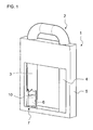
- An in Fig.1 illustrated rollover protection system 1 has a rollover body 2, which is essentially formed of two mutually connected at the head side about a kind of cross bar stirrup legs 3.4 and is in a rest position.
- the arrangement of a pyrotechnic actuator 6 can be seen in the left-hand bent leg 3 broken down by drawing. Information such as left, right or above and below refer to the graphic representation.
- the holder is formed by a not shown Berstelement which secures the position of the rollover body 2 in the rest position and prevents withdrawal of the rollover body 2 or the backup against unintentional rattling illustrated rest position of the rollover body 2 represents.
- the bursting element is the holding member between the vehicle-fixed part of the rollover protection system 1 and the extendable rollover body 2. Es is located on the one hand in opposite holes 7 a lower Traverse of the housing 5 and on the other in opposite holes 8 of the end-side left stirrup leg. 3
- the pyrotechnic actuator 6 is seated in this embodiment in the lower end of the left stirrup leg 3.
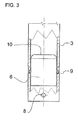
- the locking elements 9 engage in holes of the left stirrup leg 3, which are assigned to this. If the pyrotechnic actuator 6 is ignited, the compressed gases escape at the upper end of the pyrotechnic generator 10. They fill the rollover body 2, i. they are passed through the left stirrup leg 3 via the transverse yoke in the right stirrup leg 4. The pressure force is so great that first the bursting element is destroyed at its predetermined breaking point. The other compressed gases ensure that the rollover body is positioned like a "rocket". In the extended position, the rollover body 2 locks.
- the components required for the function of the active rollover protection system 1, such as the guide and the locking unit for the erected rollover body 2, are not shown, but are well known from the relevant industrial property rights, in particular the applicant.
- the bursting element next to a predetermined breaking point at one end has a head and is fixed in the area of the other end by a securing means, such as a lock washer in the position.
- a securing means such as a lock washer
Landscapes
- Engineering & Computer Science (AREA)
- Mechanical Engineering (AREA)
- Automotive Seat Belt Assembly (AREA)
- Actuator (AREA)
- Air Bags (AREA)
Applications Claiming Priority (1)
| Application Number | Priority Date | Filing Date | Title |
|---|---|---|---|
| DE102007029097A DE102007029097B4 (de) | 2007-06-21 | 2007-06-21 | Überrollschutzsystem für Kraftfahrzeuge mit zumindest einem pyrotechnisch aufstellbaren Überrollkörper |
Publications (2)
| Publication Number | Publication Date |
|---|---|
| EP2006164A2 true EP2006164A2 (fr) | 2008-12-24 |
| EP2006164A3 EP2006164A3 (fr) | 2009-08-05 |
Family
ID=39720377
Family Applications (1)
| Application Number | Title | Priority Date | Filing Date |
|---|---|---|---|
| EP08158249A Withdrawn EP2006164A3 (fr) | 2007-06-21 | 2008-06-13 | Système de protection contre les tonneaux pour véhicules automobiles dotés d'au moins un arceau de sécurité pyrotechnique pouvant être monté activement |
Country Status (3)
| Country | Link |
|---|---|
| US (1) | US20090020994A1 (fr) |
| EP (1) | EP2006164A3 (fr) |
| DE (1) | DE102007029097B4 (fr) |
Cited By (3)
| Publication number | Priority date | Publication date | Assignee | Title |
|---|---|---|---|---|
| EP2329996A1 (fr) * | 2010-09-23 | 2011-06-08 | ISE Automotive GmbH | Unité d'entraînement d'arceau de sécurité pour le logement d'un arceau de sécurité à partir d'une position de logement dans une position de renversement et système de protection contre les tonneaux pour véhicules automobiles |
| EP2384939A1 (fr) * | 2011-02-04 | 2011-11-09 | ISE Automotive GmbH | Système de protection contre les tonneaux pour des véhicules automobiles |
| AT515658B1 (de) * | 2014-06-04 | 2015-11-15 | Hirtenberger Automotive Safety | Überrollkörper für Fahrzeuge |
Families Citing this family (8)
| Publication number | Priority date | Publication date | Assignee | Title |
|---|---|---|---|---|
| DE102004035015B3 (de) * | 2004-07-20 | 2005-12-08 | Ise Innomotive Systems Europe Gmbh | Überrollschutzsystem für Kraftfahrzeuge mit versenkbarem Dach |
| DE102007013954A1 (de) * | 2007-03-23 | 2008-09-25 | Automotive Group Ise Innomotive Systems Europe Gmbh | Überrollschutzsystem für Kraftfahrzeuge mit einem sensorgesteuert aktiv aufstellbaren Überrollkörper |
| DE102007046535A1 (de) * | 2007-09-28 | 2009-04-02 | Dr. Ing. H.C. F. Porsche Aktiengesellschaft | Kraftfahrzeug, insbesondere Cabriolet, mit einer hinter den Sitzen angeordneten Überrollschutzvorrichtung |
| DE102009010189A1 (de) * | 2009-02-23 | 2010-08-26 | Dr. Ing. H.C. F. Porsche Aktiengesellschaft | Messgerät zur Bestimmung des Überlebensraumes in einem Kraftfahrzeug |
| DE102013101210B4 (de) * | 2013-02-07 | 2017-09-21 | Benteler Automobiltechnik Gmbh | Fahrzeugschutzvorrichtung |
| DE102013103771A1 (de) * | 2013-04-15 | 2014-10-16 | Benteler Automobiltechnik Gmbh | Überrollschutzvorrichtung für ein Kraftfahrzeug |
| DE102014009760A1 (de) | 2014-07-01 | 2015-02-19 | Daimler Ag | Überrollschutzvorrichtung für einen Kraftwagen |
| US10390831B2 (en) * | 2015-11-10 | 2019-08-27 | Covidien Lp | Endoscopic reposable surgical clip applier |
Citations (6)
| Publication number | Priority date | Publication date | Assignee | Title |
|---|---|---|---|---|
| DE954021C (de) | 1953-08-28 | 1956-12-13 | Snecma | Vorrichtung zur selbsttaetigen Regelung eines Rueckstossantriebes, vorzugsweise einer Rakete |
| DE4342401A1 (de) | 1993-12-13 | 1995-06-14 | Teves Gmbh Alfred | Überrollbügel für Kraftfahrzeuge |
| DE19906912C1 (de) | 1999-02-19 | 2000-04-13 | Ise Gmbh | Überroll-Schutzsystem für Kraftfahrzeuge |
| DE10040649C1 (de) | 2000-08-19 | 2001-09-13 | Ise Gmbh | Überrollschutzsystem |
| DE19960764B4 (de) | 1999-12-16 | 2005-09-29 | Autoliv Development Ab | Pyrotechnisch angetriebener Überrollbügel für Kraftfahrzeuge |
| DE102005004646B3 (de) | 2005-02-02 | 2006-03-02 | Ise Innomotive Systems Europe Gmbh | Überrollschutzsystem für Kraftfahrzeuge mit einem Überrollkörper, dessen Bügelkopf U-förmig gerundet ist |
Family Cites Families (15)
| Publication number | Priority date | Publication date | Assignee | Title |
|---|---|---|---|---|
| DE4324785A1 (de) * | 1993-07-23 | 1995-01-26 | Bayerische Motoren Werke Ag | Befestigungsvorrichtung für einen Umlenkbeschlag |
| DE19501522A1 (de) * | 1994-01-29 | 1995-08-03 | Volkswagen Ag | Überrollschutzvorrichtung für eine Cabriolet |
| DE19523929A1 (de) * | 1995-06-30 | 1997-01-09 | Daimler Benz Ag | Kraftfahrzeug, insbesondere offener Personenkraftwagen |
| US5845937A (en) * | 1997-02-10 | 1998-12-08 | Morton International, Inc. | Structural assembly |
| DE19922674A1 (de) * | 1999-05-18 | 2000-11-23 | Goetz Coenen | Pyrotechnischer Aktuator |
| JP2001039249A (ja) * | 1999-07-30 | 2001-02-13 | Honda Motor Co Ltd | 自動車の車体構造 |
| JP2003080985A (ja) * | 2001-06-26 | 2003-03-19 | Nhk Spring Co Ltd | 自動車用シート装置 |
| DE10219447B4 (de) * | 2002-05-02 | 2005-10-20 | Ise Gmbh | Überrollschutzsystem für Kraftfahrzeuge mit einer selbsthaltenden Entriegelungseinrichtung |
| GB0319981D0 (en) * | 2003-08-27 | 2003-10-01 | Ford Global Tech Llc | Roll bar assembly for a vehicle |
| WO2005087536A1 (fr) * | 2004-03-09 | 2005-09-22 | C. Rob. Hammerstein Gmbh & Co. Kg | Appuie-tête doté d'un élément d'appui pour siège de véhicule |
| GB0423709D0 (en) * | 2004-10-26 | 2004-11-24 | Ford Global Tech Llc | Motor vehicles incorporating deployable roll bar assemblies |
| GB0513278D0 (en) * | 2005-07-01 | 2005-08-03 | Delphi Tech Inc | Head restraint system |
| US7690684B2 (en) * | 2005-09-07 | 2010-04-06 | Honda Motor Co., Ltd. | Vehicle occupant protection apparatus and startup method of same |
| US7384067B2 (en) * | 2006-01-06 | 2008-06-10 | Autoliv Asp, Inc. | Rollover protection for motor vehicles |
| US20070200330A1 (en) * | 2006-02-24 | 2007-08-30 | Dan Tang | Occupant Safety Device For Roof Reinforcement |
-
2007
- 2007-06-21 DE DE102007029097A patent/DE102007029097B4/de not_active Expired - Fee Related
-
2008
- 2008-06-13 EP EP08158249A patent/EP2006164A3/fr not_active Withdrawn
- 2008-06-23 US US12/143,908 patent/US20090020994A1/en not_active Abandoned
Patent Citations (6)
| Publication number | Priority date | Publication date | Assignee | Title |
|---|---|---|---|---|
| DE954021C (de) | 1953-08-28 | 1956-12-13 | Snecma | Vorrichtung zur selbsttaetigen Regelung eines Rueckstossantriebes, vorzugsweise einer Rakete |
| DE4342401A1 (de) | 1993-12-13 | 1995-06-14 | Teves Gmbh Alfred | Überrollbügel für Kraftfahrzeuge |
| DE19906912C1 (de) | 1999-02-19 | 2000-04-13 | Ise Gmbh | Überroll-Schutzsystem für Kraftfahrzeuge |
| DE19960764B4 (de) | 1999-12-16 | 2005-09-29 | Autoliv Development Ab | Pyrotechnisch angetriebener Überrollbügel für Kraftfahrzeuge |
| DE10040649C1 (de) | 2000-08-19 | 2001-09-13 | Ise Gmbh | Überrollschutzsystem |
| DE102005004646B3 (de) | 2005-02-02 | 2006-03-02 | Ise Innomotive Systems Europe Gmbh | Überrollschutzsystem für Kraftfahrzeuge mit einem Überrollkörper, dessen Bügelkopf U-förmig gerundet ist |
Cited By (4)
| Publication number | Priority date | Publication date | Assignee | Title |
|---|---|---|---|---|
| EP2329996A1 (fr) * | 2010-09-23 | 2011-06-08 | ISE Automotive GmbH | Unité d'entraînement d'arceau de sécurité pour le logement d'un arceau de sécurité à partir d'une position de logement dans une position de renversement et système de protection contre les tonneaux pour véhicules automobiles |
| EP2384939A1 (fr) * | 2011-02-04 | 2011-11-09 | ISE Automotive GmbH | Système de protection contre les tonneaux pour des véhicules automobiles |
| AT515658B1 (de) * | 2014-06-04 | 2015-11-15 | Hirtenberger Automotive Safety | Überrollkörper für Fahrzeuge |
| AT515658A4 (de) * | 2014-06-04 | 2015-11-15 | Hirtenberger Automotive Safety | Überrollkörper für Fahrzeuge |
Also Published As
| Publication number | Publication date |
|---|---|
| US20090020994A1 (en) | 2009-01-22 |
| DE102007029097B4 (de) | 2009-06-18 |
| DE102007029097A1 (de) | 2009-01-02 |
| EP2006164A3 (fr) | 2009-08-05 |
Similar Documents
| Publication | Publication Date | Title |
|---|---|---|
| DE102007029097B4 (de) | Überrollschutzsystem für Kraftfahrzeuge mit zumindest einem pyrotechnisch aufstellbaren Überrollkörper | |
| EP1736376A2 (fr) | Module pré assemblé pour un véhicule cabriolet | |
| EP1745991B1 (fr) | Système de retenue d'un passager d'un véhicule avec un coussin gonflable | |
| DE102008039514A1 (de) | Einrichtung für ein Strukturbauteil eines Kraftwagens | |
| DE10007343A1 (de) | Sicherheitseinrichtung für die Insassen eines Fahrzeugs, insbesondere für ein Kraftfahrzeug | |
| EP1757497B1 (fr) | Dispositif pyrotechnique de commande pour un moyen de retenue placé dans un véhicule automobile | |
| DE60130018T2 (de) | Anordnung zur schwächung einer konstruktion | |
| DE102007052973A1 (de) | Airbagmodul, Airbagmodulanordnung und Befestigungsverfahren | |
| EP2001712B1 (fr) | Dispositif de protection des personnes dans des vehicules automobiles | |
| DE102006057030A1 (de) | Überrollschutzsystem für Kraftfahrzeuge mit einem sensorgesteuert aktiv aufstellbaren Überrollkörper | |
| WO2016045775A1 (fr) | Système de retenue d'occupant de véhicule | |
| DE10039800B4 (de) | Fahrzeugdach, insbesondere für ein Kraftfahrzeug | |
| EP1955908B1 (fr) | Système de protection en cas de tonneaux pour véhicules automobiles comprenant un arceau orientable dirigé par capteur pouvant être placé activement | |
| WO2005044645A1 (fr) | Actionneur pour systeme antichoc d'un vehicule | |
| EP1547873B1 (fr) | système d'arceau de sécurité pour véhicule avec arceau déployable | |
| DE10039802B4 (de) | Sicherheitseinrichtung für die Insassen eines Fahrzeugs, insbesondere eines Kraftfahrzeugs | |
| WO2006122535A1 (fr) | Systeme d'airbag pour vehicule automobile | |
| EP1935696A1 (fr) | Véhicule automobile doté d'un dispositif de sécurité | |
| DE102005028967B4 (de) | Betätigungsvorrichtung und Verfahren zum Betreiben einer Betätigungsvorrichtung | |
| DE102004056359B3 (de) | Überrollschutzeinrichtung | |
| EP1955907B1 (fr) | Système de protection avec arceau de sécurité pour des véhicules automobiles | |
| DE10039801B4 (de) | Fahrzeugdach, insbesondere für ein Kraftfahrzeug | |
| DE102011082154A1 (de) | Pedalanordnung mit Sicherheitseinrichtung | |
| DE102011082150A1 (de) | Pedalanordnung mit Sicherheitseinrichtung | |
| DE102017007380A1 (de) | Instrumententafel für ein Fahrzeug mit einem Beifahrerairbag sowie Verfahren zum Auslösen des Beifahrerairbags |
Legal Events
| Date | Code | Title | Description |
|---|---|---|---|
| PUAI | Public reference made under article 153(3) epc to a published international application that has entered the european phase |
Free format text: ORIGINAL CODE: 0009012 |
|
| AK | Designated contracting states |
Kind code of ref document: A2 Designated state(s): AT BE BG CH CY CZ DE DK EE ES FI FR GB GR HR HU IE IS IT LI LT LU LV MC MT NL NO PL PT RO SE SI SK TR |
|
| AX | Request for extension of the european patent |
Extension state: AL BA MK RS |
|
| PUAL | Search report despatched |
Free format text: ORIGINAL CODE: 0009013 |
|
| AK | Designated contracting states |
Kind code of ref document: A3 Designated state(s): AT BE BG CH CY CZ DE DK EE ES FI FR GB GR HR HU IE IS IT LI LT LU LV MC MT NL NO PL PT RO SE SI SK TR |
|
| AX | Request for extension of the european patent |
Extension state: AL BA MK RS |
|
| AKX | Designation fees paid | ||
| STAA | Information on the status of an ep patent application or granted ep patent |
Free format text: STATUS: THE APPLICATION IS DEEMED TO BE WITHDRAWN |
|
| 18D | Application deemed to be withdrawn |
Effective date: 20100206 |
|
| REG | Reference to a national code |
Ref country code: DE Ref legal event code: 8566 |