EP2006164A2 - Rollover protection system for motor vehicles with at least one pyrotechnically positioned roll-bar - Google Patents
Rollover protection system for motor vehicles with at least one pyrotechnically positioned roll-bar Download PDFInfo
- Publication number
- EP2006164A2 EP2006164A2 EP08158249A EP08158249A EP2006164A2 EP 2006164 A2 EP2006164 A2 EP 2006164A2 EP 08158249 A EP08158249 A EP 08158249A EP 08158249 A EP08158249 A EP 08158249A EP 2006164 A2 EP2006164 A2 EP 2006164A2
- Authority
- EP
- European Patent Office
- Prior art keywords
- rollover
- protection system
- rollover protection
- pyrotechnic actuator
- rollover body
- Prior art date
- Legal status (The legal status is an assumption and is not a legal conclusion. Google has not performed a legal analysis and makes no representation as to the accuracy of the status listed.)
- Withdrawn
Links
Images


Classifications
-
- B—PERFORMING OPERATIONS; TRANSPORTING
- B60—VEHICLES IN GENERAL
- B60R—VEHICLES, VEHICLE FITTINGS, OR VEHICLE PARTS, NOT OTHERWISE PROVIDED FOR
- B60R21/00—Arrangements or fittings on vehicles for protecting or preventing injuries to occupants or pedestrians in case of accidents or other traffic risks
- B60R21/02—Occupant safety arrangements or fittings, e.g. crash pads
- B60R21/13—Roll-over protection
- B60R2021/132—Roll bars for convertible vehicles
- B60R2021/134—Roll bars for convertible vehicles movable from a retracted to a protection position
- B60R2021/135—Roll bars for convertible vehicles movable from a retracted to a protection position automatically during an accident
Definitions
- the invention relates to a rollover protection system for motor vehicles according to the preamble of claim 1.
- Such rollover protection systems serve to protect the occupants in motor vehicles without a protective roof, typically in convertibles or roadsters during a rollover, since the vehicle will roll over the deployed rollover body, which provides the occupants with a survival space.
- each vehicle seat installed in the passenger compartment in a height-invariable manner, i. rigid to assign U-shaped roll bar.
- This solution is typically used in roadsters to underline the sporty appearance.
- active rollover protection systems typically have one in a vehicle-fixed guide body guided U-shaped roll bar or a roll body formed from a profile body, wherein the guide body in a cassette housing having side parts and a bottom part is fixed.
- This roll bar or rollover body is held in the normal state against the biasing force of at least one drive compression spring by a holding device in a position, a rest position, and is in the rollover case, sensor-controlled releasing the holding device, by the spring force of the drive compression spring in an upper, protective Position can be brought, with a then entering interlocking operative engagement locking device, the re-entry lock, a pushing back of the roll bar prevented.
- each vehicle seat is associated with a cassette.
- Such a cassette construction of an active rollover protection system with a U-shaped roll bar shows, for example, the DE 100 40 649 C1 ,
- rollover protection systems with an approximately the entire vehicle width spanning, actively deployable roll bar are known.
- Both the seat-mounted cassette constructions as well as the roll bars spanning approximately the entire width of the vehicle are marketed and in operation in various embodiments adapted to the respective vehicle type.
- Typical releasable holding devices consist, for example, of a holding member attached to the rollover body and a triggering mechanism, typically a pawl mechanism, on a sensor-controlled actuator, which is actuated by a so-called electrically activatable triggering magnet or alternatively by a pyrotechnic element corresponding to FIG DE 43 42 401 A1 can be formed.
- a pyrotechnic element typically has a pyrotechnic propellant (charge) incorporated in a housing of a cylinder-piston unit, a small piston rod (pin-withdrawing or pin-ejecting) actuating the triggering mechanism through the ignited pyrotechnic propellant charge and thus retaining the fixed one Rollover body picks up.
- a pyrotechnic propellant charge
- a small piston rod pin-withdrawing or pin-ejecting
- FIG. 2 shows an example of how the upper part of a roll bar can be driven directly by a gas generator.
- the piston defines a substantially cylindrical expansion chamber, to which a gas generator is attached. If the pyrotechnic ignition in the vehicle-mounted gas generator ignited by an electrical voltage, the resulting gas builds up in the expansion chamber to a pneumatic pressure, which displaces the piston.
- the roll bar is extended in this way. Except in the Fig. 2 also described indirect drive by the pressure generated by the gas generator is possible, in any case, the gas generator is arranged fixed to the vehicle direct drive a rollover bar.
- the DE 954 021 B discloses a device for the automatic regulation of a recoil drive, preferably a rocket, wherein the thrust is controlled by the amount of reactants. This is a known drive in the field of aviation.
- the holding device is formed from a locking mandrel with an undercut flange, which communicates with the movable member and a body-mounted locking ring with movable locking hooks for releasable operative engagement with the undercut on the locking mandrel.
- the object of the invention is to provide a reliable and cost-effective rollover protection system that can be integrated into a vehicle to save space.
- Characteristic of the rollover protection system according to the invention is that the pyrotechnic actuator is attached to the deployable part of the rollover protection system, the rollover body in a pressure chamber of the rollover body, wherein the pyrotechnic actuator is a gas generator.
- the rollover body is always the extendable part of the rollover protection system.
- the rollover protection system according to the invention allows a very compact design of the entire rollover protection system. On additional components such as drive piston, piston rod, cylinder tube, Aufstellfedern and the like, which are required in the known from the prior art rollover protection systems, can be completely eliminated.
- the rollover protection system according to the invention is characterized by its cost-effective, unreliable, reliable and highly effective Structure, which, as described above, in particular results from the small number of required components.
- the pyrotechnic actuator is located in a kind of "pressure chamber" of the rollover body.
- the pressure chamber is already present by the predetermined shape of the rollover body in almost all cases of execution, the rollover protection systems introduced on the market.
- the invention uses the existing cavities without requiring additional components.
- the pressure chamber can be purposefully reduced by a bulkhead element located above the pyrotechnic actuator in order to be able to use pyrotechnic actuators with smaller charges.
- the pyrotechnic actuator is so installed in the pressure chamber that there is enough space around the pyrotechnic actuator, so that the pressure gases around the actuator can escape around and so the corresponding thrust arises.
- connection between the pulse-generating sensor unit and the pyrotechnic actuator in the basic position of the rollover body is formed by contacts, so that an electrical supply line to the pyrotechnic actuator is not torn off in the raising movement.
- the pyrotechnic actuator can be replaced after its ignition, without having to rewire the pyrotechnic actuator.
- the pyrotechnic actuators or gas generators have a very high energy input, so that it is possible without problems to fill the different cavities with their different Voluminas with compressed gas.
- the installation of the rollover body works like a "rocket drive”.
- the holder of the rollover body is released by the pyrotechnic actuator after its "ignition".
- the holder can be formed by a destructive "bursting".
- the bursting element is a connecting element between the vehicle-fixed part of the rollover protection system and the extendable part of the rollover protection system, the rollover body.
- the bursting element can have a defined predetermined breaking point which is destroyed when the pyrotechnic actuator is ignited. Due to the described holder via a bursting element of the rollover body is held in its retracted position, the rest position, so it does not cause rattling noises in road bumps and improper pulling out of the rollover body is also prevented.
- the holder may also be formed by a conventional latch arrangement.
- the exiting gas pressure then first opens the pawl before the remaining gas pressure sets up the rollover body.
- a latch arrangement is a kind of "rocker".
- This rocker has two arms, with one arm with a corresponding shape ensures that the rollover body is held, the other arm takes the Pressure of the propellant gases and thus dissolves the bracket.
- this second arm has a large surface to effectively absorb the compressed gases accordingly.
- the second arm can sit directly below the pressure chamber of the rollover body and the first arm next to the pressure chamber, thus the pressure of the propellant gases is advantageously only on the second lever arm.
- An alternative design provides an additional pressure chamber element, which lies at least partially within the rollover body or can at least partially surround it.
- the additional pressure chamber element is then fixedly attached to the vehicle-fixed part of the rollover protection system.
- smaller pyrotechnic charges can be used by this alternative design.
- the overroll protection system may have various embodiments, e.g. a pipe construction for the extendable part of the rollover protection system, so the actual rollover body, as well as a cassette system which is formed by profiles.
- the materials used can be very different.
- steel, plastic, in particular fiber-reinforced plastic, magnesium and aluminum can be used.
- plastic in particular fiber-reinforced plastic, magnesium and aluminum
- a combination of different materials is conceivable.
- the rollover protection system according to the invention is characterized i.a. due to its compact design.
- An additional space saving can be achieved according to a development of the invention in that the bar arms or the profile body of the rollover body in close proximity to the bottom of the rollover protection system or, if space reasons, this is dispensed with in the immediate vicinity of the car structure, located below the Rollover body is located.
- the deployment stroke results from the difference between retracted rollover body and extended rollover body.
- the more space underneath this tangent to the occupants the greater the safety for the vehicle occupants in the event of a rollover.
- the training improves protection for the vehicle occupants in a complementary manner.
- the pyrotechnic actuator can be fixed with a variety of attachment methods on the rollover body. Both non-positive, positive and cohesive connections are possible. By way of example, only glands, riveting, snap-in connections and gluing are mentioned here.
- the space-saving accommodation of the pyrotechnic actuator provides space in the periphery, so that space for through-loading or other components is created.
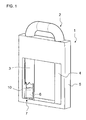
- An in Fig.1 illustrated rollover protection system 1 has a rollover body 2, which is essentially formed of two mutually connected at the head side about a kind of cross bar stirrup legs 3.4 and is in a rest position.
- the arrangement of a pyrotechnic actuator 6 can be seen in the left-hand bent leg 3 broken down by drawing. Information such as left, right or above and below refer to the graphic representation.
- the holder is formed by a not shown Berstelement which secures the position of the rollover body 2 in the rest position and prevents withdrawal of the rollover body 2 or the backup against unintentional rattling illustrated rest position of the rollover body 2 represents.
- the bursting element is the holding member between the vehicle-fixed part of the rollover protection system 1 and the extendable rollover body 2. Es is located on the one hand in opposite holes 7 a lower Traverse of the housing 5 and on the other in opposite holes 8 of the end-side left stirrup leg. 3
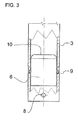
- the pyrotechnic actuator 6 is seated in this embodiment in the lower end of the left stirrup leg 3.
- the locking elements 9 engage in holes of the left stirrup leg 3, which are assigned to this. If the pyrotechnic actuator 6 is ignited, the compressed gases escape at the upper end of the pyrotechnic generator 10. They fill the rollover body 2, i. they are passed through the left stirrup leg 3 via the transverse yoke in the right stirrup leg 4. The pressure force is so great that first the bursting element is destroyed at its predetermined breaking point. The other compressed gases ensure that the rollover body is positioned like a "rocket". In the extended position, the rollover body 2 locks.
- the components required for the function of the active rollover protection system 1, such as the guide and the locking unit for the erected rollover body 2, are not shown, but are well known from the relevant industrial property rights, in particular the applicant.
- the bursting element next to a predetermined breaking point at one end has a head and is fixed in the area of the other end by a securing means, such as a lock washer in the position.
- a securing means such as a lock washer
Abstract
Description
Die Erfindung bezieht sich auf ein Überrollschutzsystem für Kraftfahrzeuge gemäß dem Oberbegriff des Anspruchs 1.The invention relates to a rollover protection system for motor vehicles according to the preamble of
Derartige Überrollschutzsysteme dienen zum Schutz der Insassen in Kraftfahrzeugen ohne schützendes Dach, typischerweise in Cabriolets oder Roadstern bei einem Überschlag, da das Fahrzeug über den aufgestellten Überrollkörper abrollen wird, der den Insassen einen Überlebensraum bietet.Such rollover protection systems serve to protect the occupants in motor vehicles without a protective roof, typically in convertibles or roadsters during a rollover, since the vehicle will roll over the deployed rollover body, which provides the occupants with a survival space.
Es ist dabei bekannt, einen die gesamte Fahrzeugbreite überspannenden, als Teil der Karosserie ausgebildeten Überrollbügel vorzusehen. Bei dieser Lösung wird der erhöhte Luftwiderstand und das Auftreten von Fahrgeräuschen als nachteilig empfunden, abgesehen von der Beeinträchtigung des Fahrzeugaussehens.It is known to provide an over the entire vehicle width spanning, designed as part of the body roll bar. In this solution, the increased air resistance and the occurrence of driving noise is perceived as disadvantageous, apart from the impairment of the vehicle appearance.
Es ist auch bekannt, jedem Fahrzeugsitz einen höhenunveränderlich fest im Fahrgastraum installierten, d.h. starren, U-förmigen Überrollbügel zuzuordnen. Diese Lösung wird typischerweise bei Roadstern zur Unterstreichung des sportlichen Aussehens eingesetzt.It is also known to have each vehicle seat installed in the passenger compartment in a height-invariable manner, i. rigid to assign U-shaped roll bar. This solution is typically used in roadsters to underline the sporty appearance.
Weit verbreitet bei Cabriolets sind konstruktive Lösungen, bei denen der Überrollkörper im Normalzustand eingefahren ist, und im Gefahrenfall, also bei einem drohenden Überschlag, sehr schnell in eine schützende Position aufgestellt wird, um zu verhindern, dass die Fahrzeuginsassen durch das sich überschlagende Fahrzeug erdrückt werden.Widely used in convertibles are constructive solutions in which the rollover body is retracted in the normal state, and in case of danger, so at a threatening rollover, is placed very quickly in a protective position to prevent the vehicle occupants are crushed by the overturning vehicle ,
Diese sogenannten "aktiven" Überrollschutzsysteme weisen typischerweise einen in einem fahrzeugfesten Führungskörper geführten U-förmigen Überrollbügel oder einen aus einem Profilkörper gebildeten Überrollkörper auf, wobei der Führungskörper in einem Kassetten-Gehäuse, das Seitenteile und ein Bodenteil aufweist, befestigt ist. Dieser Überrollbügel bzw. Überrollkörper wird im Normalzustand gegen die Vorspannkraft mindestens einer Antriebs-Druckfeder durch eine Haltevorrichtung in einer Stellung, einer Ruhelage gehalten, und ist im Überschlagfall, sensorgesteuert unter Lösen der Haltevorrichtung, durch die Federkraft der Antriebs-Druckfeder in eine obere, schützende Stellung bringbar, wobei eine dann in verzahnenden Wirkeingriff tretende Verriegelungseinrichtung, die Wiedereinfahrsperre, ein Zurückdrücken des Überrollbügels verhindert. Dabei ist typischerweise jedem Fahrzeugsitz eine Kassette zugeordnet. Eine derartige Kassetten-Konstruktion eines aktiven Überrollschutzsystems mit einem U-förmigen Überrollbügel zeigt beispielsweise die
Des weiteren sind auch Überrollschutzsysteme mit einem annähernd die gesamte Fahrzeugbreite überspannenden, aktiv aufstellbaren Überrollbügel bekannt.Furthermore, rollover protection systems with an approximately the entire vehicle width spanning, actively deployable roll bar are known.
Sowohl die sitzbezogenen Kassetten-Konstruktionen als auch die annähernd die gesamte Fahrzeugbreite überspannenden Überrollbügel sind in vielfältigen Ausführungsformen, angepasst an den jeweiligen Fahrzeugtyp, auf dem Markt eingeführt und in Betrieb.
Es sind dabei auch Fahrzeuge bekannt, bei denen ein Überrollbügel aus einer horizontalen Ruhelage in eine vertikale Schutzposition hochschwenkbar ist.Both the seat-mounted cassette constructions as well as the roll bars spanning approximately the entire width of the vehicle are marketed and in operation in various embodiments adapted to the respective vehicle type.
There are also known vehicles in which a roll bar from a horizontal rest position can be pivoted into a vertical protection position.
Bei all diesen unterschiedlichen Ausgestaltungen des Überrollschutzes, die auch unter Verwendung der Erfindung gebildet werden können, ist es notwendig, eine im Gefahrenfall auslösbare Haltevorrichtung für den in einer Ruhelage fixierten Überrollkörper und einen Antrieb zum Aufstellen bzw. Verschwenken des jeweiligen Überrollkörpers nach dem Lösen der Haltevorrichtung vorzusehen.In all these different embodiments of the rollover protection, which can also be formed using the invention, it is necessary to trigger a releasable in case of danger holding device for the fixed in a rest position rollover body and a drive for Erecting or pivoting of the respective rollover body to provide after the release of the holding device.
Typische auslösbare Haltevorrichtungen bestehen beispielsweise aus einem am Überrollkörper angebrachten Halteglied und einer Auslösemechanik, typischerweise einer Klinkenmechanik, an einem sensorgesteuerten Aktuator, der durch einen sogenannten elektrisch aktivierbaren Auslösemagneten oder alternativ durch ein pyrotechnisches Element entsprechend der
Durch die
Die
Aus der
Mit steigender Anzahl an Bauteilen zur Herstellung der Haltevorrichtung steigt auch das Risiko für Fehlfunktionen. Diese resultieren u.a. aus einer Addition der unterschiedlichen Toleranzen. Ferner handelt es sich bei der gesamten Halte- und Aufstelleinheit um eine zusätzliche und somit teure Ausführungsform; aufgrund des Kostendrucks in der Automobilzulieferindustrie wird jedoch der Ruf nach kostengünstigen Systemen immer lauter.With increasing number of components for the production of the holding device also increases the risk of malfunction. These result u.a. from an addition of the different tolerances. Furthermore, the entire holding and erection unit is an additional and therefore expensive embodiment; However, due to the cost pressure in the automotive supply industry, the call for cost-effective systems is becoming louder and louder.
Aufgabe der Erfindung ist es ein zuverlässiges und kostengünstiges Überrollschutzsystem bereitzustellen, das sich platzsparend in ein Fahrzeug integrieren lässt.The object of the invention is to provide a reliable and cost-effective rollover protection system that can be integrated into a vehicle to save space.
Die Erfindung löst die Aufgabe durch ein Überrollschutzsystem mit den Merkmalen des Anspruchs 1. Vorteilhafte Weiterbildungen der Erfindung sind in den Unteransprüchen angegeben.The invention solves the problem by a rollover protection system having the features of
Kennzeichnend für das erfindungsgemäße Überrollschutzsystem ist, dass der pyrotechnische Aktuator am aufstellbaren Teil des Überrollschutzsystems, dem Überrollkörper in einer Druckkammer des Überrollkörpers , befestigt ist, wobei der pyrotechnische Aktuator ein Gasgenerator ist. Im Rahmen der Erfindung handelt es sich bei dem Überrollkörper immer um den ausfahrbaren Teil des Überrollschutzsystems.Characteristic of the rollover protection system according to the invention is that the pyrotechnic actuator is attached to the deployable part of the rollover protection system, the rollover body in a pressure chamber of the rollover body, wherein the pyrotechnic actuator is a gas generator. In the context of the invention, the rollover body is always the extendable part of the rollover protection system.
Das erfindungsgemäße Überrollschutzsystem ermöglicht eine sehr kompakte Bauweise des gesamten Überrollschutzsystems. Auf zusätzliche Bauteile wie Antriebskolben, Kolbenstange, Zylinderrohr, Aufstellfedern und dergleichen, die bei dem aus dem Stand der Technik bekannten Überrollschutzsystemen erforderlich sind, kann vollständig verzichtet werden. Somit zeichnet sich das erfindungsgemäße Überrollschutzsystem durch seinen kostengünstigen, unanfälligen, zuverlässigen und hochwirksamen Aufbau aus, der, wie oben beschrieben, insbesondere aus der geringen Anzahl erforderlicher Bauteile resultiert.The rollover protection system according to the invention allows a very compact design of the entire rollover protection system. On additional components such as drive piston, piston rod, cylinder tube, Aufstellfedern and the like, which are required in the known from the prior art rollover protection systems, can be completely eliminated. Thus, the rollover protection system according to the invention is characterized by its cost-effective, unreliable, reliable and highly effective Structure, which, as described above, in particular results from the small number of required components.
Der pyrotechnische Aktuator befindet sich in einer Art "Druckkammer" des Überrollkörpers. Die Druckkammer ist durch die vorgegebene Form des Überrollkörpers in nahezu allen Ausführungsfällen, der auf dem Markt eingeführten Überrollschutzsysteme, bereits vorhanden. Dies betrifft sowohl die U-förmigen Überrollkörper, welche aus Rohren gebildet werden, ebenso wie die in schalenbauweise, wie aus
Schon aus gewichts-, material- und kostentechnischen Gründen handelt es sich bei all diesen Varianten um Hohlkörper. Vorteilhafterweise nutzt die Erfindung die vorhandenen Hohlräume, ohne zusätzliche Bauteile zu benötigen.The pyrotechnic actuator is located in a kind of "pressure chamber" of the rollover body. The pressure chamber is already present by the predetermined shape of the rollover body in almost all cases of execution, the rollover protection systems introduced on the market. This concerns both the U-shaped rollover body, which are formed from tubes, as well as the shell-like, as from
Already for weight, material and cost reasons, all these variants are hollow bodies. Advantageously, the invention uses the existing cavities without requiring additional components.
Der Druckraum kann durch ein oberhalb des pyrotechnischen Aktuators gelegenes Schottelement gezielt verkleinert werden, um auch pyrotechnische Aktuatoren mit kleineren Ladungen einsetzen zu können. In diesem Fall ist der pyrotechnische Aktuator so im Druckraum eingebaut sein, dass genügend Platz um den pyrotechnischen Aktuator vorhanden ist, damit die Druckgase um den Aktuator herum entweichen können und so die entsprechende Schubkraft entsteht.The pressure chamber can be purposefully reduced by a bulkhead element located above the pyrotechnic actuator in order to be able to use pyrotechnic actuators with smaller charges. In this case, the pyrotechnic actuator is so installed in the pressure chamber that there is enough space around the pyrotechnic actuator, so that the pressure gases around the actuator can escape around and so the corresponding thrust arises.
Mit Vorteil wird die Verbindung zwischen der impulsgebenden Sensoreinheit und dem pyrotechnischen Aktuator in der Grundstellung des Überrollkörpers durch Kontakte gebildet, so dass eine elektrische Zuleitung zu dem pyrotechnischen Aktuator bei der Aufstellbewegung nicht abgerissen wird.Advantageously, the connection between the pulse-generating sensor unit and the pyrotechnic actuator in the basic position of the rollover body is formed by contacts, so that an electrical supply line to the pyrotechnic actuator is not torn off in the raising movement.
Nach einer Weiterbildung der Erfindung kann der pyrotechnische Aktuator nach dessen Zündung ausgewechselt werden, ohne dass eine neue Verdrahtung des pyrotechnischen Aktuators erfolgen muss.
Die pyrotechnischen Aktuatoren oder Gasgeneratoren haben von Hause aus ein sehr hohes Energieaufkommen, so dass es ohne Probleme möglich ist, die verschiedenen Hohlräume mit ihren unterschiedlichen Voluminas mit Druckgas zu füllen.
Im Prinzip funktioniert die Aufstellung des Überrollkörpers wie ein "Raketenantrieb".According to a development of the invention, the pyrotechnic actuator can be replaced after its ignition, without having to rewire the pyrotechnic actuator.
The pyrotechnic actuators or gas generators have a very high energy input, so that it is possible without problems to fill the different cavities with their different Voluminas with compressed gas.
In principle, the installation of the rollover body works like a "rocket drive".
In einer Ausgestaltung wird durch den pyrotechnischen Aktuator nach dessen "Zündung" auch die Halterung des Überrollkörpers gelöst. Die Halterung kann dabei durch ein sich zerstörendes "Berstelement" gebildet werden. Bei dem Berstelement handelt es sich um ein Verbindungselement zwischen dem fahrzeugfestem Teil des Überrollschutzsystems und dem ausfahrbaren Teil des Überrollschutzsystems, dem Überrollkörper. So kann das Berstelement über eine definierte Sollbruchstelle verfügen, die bei Zündung des pyrotechnischen Aktuators zerstört wird. Durch die beschriebene Halterung über ein Berstelement wird der Überrollkörper in seiner eingefahrenen Stellung, der Ruhelage, gehalten, es kommt somit nicht zu Klappergeräuschen bei Fahrbahnunebenheiten und ein missbräuchliches Herausziehen des Überrollkörpers wird ebenfalls verhindert.In one embodiment, the holder of the rollover body is released by the pyrotechnic actuator after its "ignition". The holder can be formed by a destructive "bursting". The bursting element is a connecting element between the vehicle-fixed part of the rollover protection system and the extendable part of the rollover protection system, the rollover body. Thus, the bursting element can have a defined predetermined breaking point which is destroyed when the pyrotechnic actuator is ignited. Due to the described holder via a bursting element of the rollover body is held in its retracted position, the rest position, so it does not cause rattling noises in road bumps and improper pulling out of the rollover body is also prevented.
Anstelle eines Berstelementes kann die Halterung auch durch eine herkömmliche Klinkenanordnung gebildet sein. Der austretende Gasdruck öffnet dann zunächst die Klinke, bevor der restliche Gasdruck den Überrollkörper aufstellt. Vorteilhafterweise handelt es sich bei einer solchen Klinkenanordnung um eine Art "Wippe". Diese Wippe hat zwei Arme, wobei der eine Arm mit einer entsprechenden Ausformung dafür sorgt, dass der Überrollkörper gehalten ist, der andere Arm nimmt den Druck der Treibgase auf und löst somit die Halterung. Mit Vorteil hat dieser zweite Arm eine große Oberfläche, um die Druckgase entsprechend wirksam zu absorbieren. Der zweite Arm kann unmittelbar unterhalb der Druckkammer des Überrollkörpers sitzen und der erste Arm neben der Druckkammer, somit kommt der Druck der Treibgase mit Vorteil lediglich auf den zweiten Hebelarm.Instead of a bursting element, the holder may also be formed by a conventional latch arrangement. The exiting gas pressure then first opens the pawl before the remaining gas pressure sets up the rollover body. Advantageously, such a latch arrangement is a kind of "rocker". This rocker has two arms, with one arm with a corresponding shape ensures that the rollover body is held, the other arm takes the Pressure of the propellant gases and thus dissolves the bracket. Advantageously, this second arm has a large surface to effectively absorb the compressed gases accordingly. The second arm can sit directly below the pressure chamber of the rollover body and the first arm next to the pressure chamber, thus the pressure of the propellant gases is advantageously only on the second lever arm.
Es können aber auch andere form- und/oder kraftschlüssige Verbindungen als Halterung vorgesehen sein, wie Verstemmung, Bördelung, Presspassung etc.. Auch durch den Druck der Treibgase lösbare stoffschlüssige Verbindungen sind denkbar.However, other positive and / or non-positive connections can be provided as a holder, such as caulking, flanging, press fit etc. Also by the pressure of the propellant gases releasable cohesive connections are conceivable.
Eine alternative Bauform sieht ein zusätzliches Druckkammerelement vor, welches zumindest teilweise innerhalb des Überrollkörpers liegt oder diesen zumindest teilweise umgeben kann. Das zusätzliche Druckkammerelement ist dann ortsfest an dem fahrzeugfesten Teil des Überrollschutzsystems befestigt. Mit Vorteil sind durch diese alternative Bauform kleinere pyrotechnische Ladungen einsetzbar.An alternative design provides an additional pressure chamber element, which lies at least partially within the rollover body or can at least partially surround it. The additional pressure chamber element is then fixedly attached to the vehicle-fixed part of the rollover protection system. Advantageously, smaller pyrotechnic charges can be used by this alternative design.
Das Überollschutzsystem kann vielfältige Ausgestaltungsformen aufweisen, so kommt z.B. eine Rohrkonstruktion für den ausfahrbaren Teil des Überrollschutzsystems, also dem eigentlichen Überrollkörper, genauso in Betracht, wie ein Kassettensystem welches durch Profile gebildet wird.The overroll protection system may have various embodiments, e.g. a pipe construction for the extendable part of the rollover protection system, so the actual rollover body, as well as a cassette system which is formed by profiles.
Auch die verwendeten Materialien können sehr unterschiedlich sein. So können z.B. Stahl, Kunststoff, insbesondere faserverstärkter Kunststoff, Magnesium und Aluminium Verwendung finden. Hierbei ist selbstverständlich auch eine Kombination der unterschiedlichen Materialien denkbar.The materials used can be very different. For example, steel, plastic, in particular fiber-reinforced plastic, magnesium and aluminum can be used. Of course, a combination of different materials is conceivable.
Das erfindungsgemäße Überrollschutzsystem zeichnet sich u.a. durch seine kompakte Bauweise aus. Eine zusätzliche Platzersparnis kann nach einer Weiterbildung der Erfindung dadurch erreicht werden, dass die Bügelschenkel oder auch der Profilkörper des Überrollkörpers in unmittelbarer Nähe zum Boden des Überrollschutzsystem oder, falls aus platztechnischen Gründen auf diesen verzichtet wird, in unmittelbarer Nähe zur Wagenstruktur, die sich unterhalb des Überrollkörpers befindet, liegen. Somit geht kein wertvoller Bauraum verloren, der für den Aufstellhub genutzt werden kann und den Überlebensraum für die Insassen vergrößert. Der Aufstellhub ergibt sich aus der Differenz zwischen eingefahrenen Überrollkörper und ausgefahrenen Überrollkörper. Je weiter der Überrollkörper ausfahren kann, desto größer wird auch die Überrolltangente. Diese ergibt sich indem man eine Tangente über den dachseitigen Windschutzscheibenrahmen hin zu den ausgefahrenen Überrollkörpern legt. Je mehr Platz sich unterhalb dieser Tangente für die Insassen bildet, desto größer ist die Sicherheit für die Fahrzeuginsassen im Falle eines Überschlags. Die Weiterbildung verbessert den Schutz für die Fahrzeuginsassen in ergänzender Weise.The rollover protection system according to the invention is characterized i.a. due to its compact design. An additional space saving can be achieved according to a development of the invention in that the bar arms or the profile body of the rollover body in close proximity to the bottom of the rollover protection system or, if space reasons, this is dispensed with in the immediate vicinity of the car structure, located below the Rollover body is located. Thus, no valuable space is lost, which can be used for the deployment and increases the survival space for the occupants. The deployment stroke results from the difference between retracted rollover body and extended rollover body. The further the rollover body can extend, the larger the rollover tangent becomes. This results from placing a tangent over the roof-side windshield frame towards the extended rollover bodies. The more space underneath this tangent to the occupants, the greater the safety for the vehicle occupants in the event of a rollover. The training improves protection for the vehicle occupants in a complementary manner.
Der pyrotechnische Aktuator kann mit den unterschiedlichsten Befestigungsmethoden am Überrollkörper fixiert werden.
Möglich sind sowohl kraftschlüssige, formschlüssige als auch stoffschlüssige Verbindungen. Exemplarisch seien hier nur Verschraubungen, Vernietungen, Rastverbindungen und Verklebungen genannt.The pyrotechnic actuator can be fixed with a variety of attachment methods on the rollover body.
Both non-positive, positive and cohesive connections are possible. By way of example, only glands, riveting, snap-in connections and gluing are mentioned here.
In ergänzender Weise sorgt die platzsparende Unterbringung des pyrotechnischen Aktuators für Raum in der Peripherie, so dass Platz für Durchlademöglichkeiten oder andere Bauteile geschaffen wird.In addition, the space-saving accommodation of the pyrotechnic actuator provides space in the periphery, so that space for through-loading or other components is created.
Anhand von mehreren in den Zeichnungen in verschiedenen Ansichten und Zuständen dargestellten vorteilhaften Ausführungsbeispielen wird die Erfindung näher erläutert.On the basis of several advantageous embodiments shown in the drawings in different views and states, the invention is explained in detail.
Es zeigen:
- Fig.1
- ein Überrollschutzsystem in Ruhelage in einer schematisierten, teilweise weggebrochenen isometrischen Ansicht, das einen pyrotechnischen Aktuator im Überrollkörper aufweist,
- Fig.2
- das System nach
Fig. 1 , jedoch im aufgestellten Zustand des Überrollkörpers, - Fig.3
- ein Überrollschutzsystem in einem schematisierten Teilausschnitt nach
Fig. 1 zur Verdeutlichung der erfindungsgemäßen Lage des pyrotechnischen Aktuators, und - Fig.4
- eine Variante des Überrollschutzsystems nach
Fig. 2 , mit einem Druckkammerelement.
- Fig.1
- a rollover protection system in rest position in a schematic, partially broken isometric view, which has a pyrotechnic actuator in the rollover body,
- Fig.2
- the system after
Fig. 1 but in the erected state of the rollover body, - Figure 3
- a rollover protection system in a schematic partial section after
Fig. 1 to illustrate the position of the pyrotechnic actuator according to the invention, and - Figure 4
- a variant of the rollover protection system according to
Fig. 2 , with a pressure chamber element.
Ein in
Angaben wie links, rechts oder oben und unten beziehen sich auf die zeichnerische Darstellung.An in
Information such as left, right or above and below refer to the graphic representation.
In der in
Der pyrotechnische Aktuator 6 sitzt bei diesem Ausführungsbeispiel im unteren Ende des linken Bügelschenkels 3. Durch zwei Rastelemente 9, die Bestandteil des pyrotechnischen Aktuators 6 sind, wird dieser in der vorgegebenen Position im Überrollkörper 2, in diesem Fall dem linken Bügelschenkel 3, gehalten. Die Rastelemente 9 verrasten in Löchern des linken Bügelschenkels 3, die diesem zugeordnet sind. Wird der pyrotechnische Aktuator 6 gezündet, entweichen am oberen Ende des pyrotechnischen Generators 10 die Druckgase. Sie füllen den Überrollkörper 2 aus, d.h. sie werden durch den linken Bügelschenkel 3 über das Querjoch in den rechten Bügelschenkel 4 geleitet. Die Druckkraft ist so groß, dass zunächst das Berstelement an seiner Sollbruchstelle zerstört wird. Die übrigen Druckgase sorgen dafür, dass der Überrollkörper wie eine "Rakete" aufgestellt wird. In der ausgefahrenen Stellung verriegelt der Überrollkörper 2.The
Die für die Funktion des aktiven Überrollschutzsystems 1 erforderlichen Bauteile wie die Führung und die Verriegelungseinheit für den aufgestellten Überrollkörper 2 sind nicht dargestellt, jedoch aus einschlägigen Schutzrechtsschriften, insbesondere der Anmelderin, hinlänglich bekannt.The components required for the function of the active
In einer hier nicht dargestellten Ausführungsform besitzt das Berstelement neben einer Sollbruchstelle einerends einen Kopf und wird im Bereich des anderen Endes durch ein Sicherungsmittel, wie einer Sicherungsscheibe, in der Lage fixiert. Somit besitzt das Berstelement eine für alle Betriebszustände sichere Lage.In one embodiment, not shown here, the bursting element next to a predetermined breaking point at one end has a head and is fixed in the area of the other end by a securing means, such as a lock washer in the position. Thus, the bursting element has a safe for all operating conditions.
- 11
- ÜberrollschutzsystemRollover protection system
- 22
- ÜberrollkörperRollover body
- 33
- Linker BügelschenkelLeft thigh
- 44
- Rechter BügelschenkelRight hanger leg
- 55
- Kassettenartiges GehäuseCassette-like housing
- 66
- Pyrotechnischer AktuatorPyrotechnic actuator
- 77
- Loch im GehäuseHole in the housing
- 88th
- Loch im BügelschenkelHole in the hanger leg
- 99
- Rastelementlocking element
- 1010
- Oberes Ende des pyrotechnischen AktuatorsUpper end of the pyrotechnic actuator
- 1111
- DruckkammerelementPressure chamber member
Claims (12)
Applications Claiming Priority (1)
| Application Number | Priority Date | Filing Date | Title |
|---|---|---|---|
| DE102007029097A DE102007029097B4 (en) | 2007-06-21 | 2007-06-21 | Rollover protection system for motor vehicles with at least one pyrotechnic deployable rollover body |
Publications (2)
| Publication Number | Publication Date |
|---|---|
| EP2006164A2 true EP2006164A2 (en) | 2008-12-24 |
| EP2006164A3 EP2006164A3 (en) | 2009-08-05 |
Family
ID=39720377
Family Applications (1)
| Application Number | Title | Priority Date | Filing Date |
|---|---|---|---|
| EP08158249A Withdrawn EP2006164A3 (en) | 2007-06-21 | 2008-06-13 | Rollover protection system for motor vehicles with at least one pyrotechnically positioned roll-bar |
Country Status (3)
| Country | Link |
|---|---|
| US (1) | US20090020994A1 (en) |
| EP (1) | EP2006164A3 (en) |
| DE (1) | DE102007029097B4 (en) |
Cited By (3)
| Publication number | Priority date | Publication date | Assignee | Title |
|---|---|---|---|---|
| EP2329996A1 (en) * | 2010-09-23 | 2011-06-08 | ISE Automotive GmbH | Roll-bar drive unit for displacing a roll-bar from a storage position into a rollover position and rollover protection for motor vehicles |
| EP2384939A1 (en) * | 2011-02-04 | 2011-11-09 | ISE Automotive GmbH | Rollover protection for motor vehicles |
| AT515658A4 (en) * | 2014-06-04 | 2015-11-15 | Hirtenberger Automotive Safety | Rollover body for vehicles |
Families Citing this family (8)
| Publication number | Priority date | Publication date | Assignee | Title |
|---|---|---|---|---|
| DE102004035015B3 (en) * | 2004-07-20 | 2005-12-08 | Ise Innomotive Systems Europe Gmbh | Rollover protection system for motor vehicles with retractable roof |
| DE102007013954A1 (en) * | 2007-03-23 | 2008-09-25 | Automotive Group Ise Innomotive Systems Europe Gmbh | Rollover protection system for motor vehicles with a sensor-controlled actively deployable rollover body |
| DE102007046535A1 (en) * | 2007-09-28 | 2009-04-02 | Dr. Ing. H.C. F. Porsche Aktiengesellschaft | Motor vehicle, in particular cabriolet, with a rollover protection device arranged behind the seats |
| DE102009010189A1 (en) * | 2009-02-23 | 2010-08-26 | Dr. Ing. H.C. F. Porsche Aktiengesellschaft | Telescopic measuring device for determining survival space in motor vehicle, has position indicating device e.g. display, provided for indicating relative position of external cylindrical housing and internal cylinder |
| DE102013101210B4 (en) * | 2013-02-07 | 2017-09-21 | Benteler Automobiltechnik Gmbh | Vehicle protection device |
| DE102013103771A1 (en) * | 2013-04-15 | 2014-10-16 | Benteler Automobiltechnik Gmbh | Rollover protection device for a motor vehicle |
| DE102014009760A1 (en) | 2014-07-01 | 2015-02-19 | Daimler Ag | Rollover protection device for a motor vehicle |
| US10390831B2 (en) * | 2015-11-10 | 2019-08-27 | Covidien Lp | Endoscopic reposable surgical clip applier |
Citations (6)
| Publication number | Priority date | Publication date | Assignee | Title |
|---|---|---|---|---|
| DE954021C (en) | 1953-08-28 | 1956-12-13 | Snecma | Device for the automatic control of a recoil drive, preferably a rocket |
| DE4342401A1 (en) | 1993-12-13 | 1995-06-14 | Teves Gmbh Alfred | Roll bars for motor vehicles |
| DE19906912C1 (en) | 1999-02-19 | 2000-04-13 | Ise Gmbh | Roll-over protection system for automobile has seat headrest acting as over-roll protection profile deployed upon crash for protecting seat passenger |
| DE10040649C1 (en) | 2000-08-19 | 2001-09-13 | Ise Gmbh | Open automobile roll bar assembly has cassette housing with U-profile side walls to take guide block in firm bond, and allow sliding movement of cross beam without free play |
| DE19960764B4 (en) | 1999-12-16 | 2005-09-29 | Autoliv Development Ab | Pyrotechnically driven roll bar for motor vehicles |
| DE102005004646B3 (en) | 2005-02-02 | 2006-03-02 | Ise Innomotive Systems Europe Gmbh | A rollover protection system for convertible car has tubular arc head composed of two partly tube-shaped shells of metal sheet |
Family Cites Families (15)
| Publication number | Priority date | Publication date | Assignee | Title |
|---|---|---|---|---|
| DE4324785A1 (en) * | 1993-07-23 | 1995-01-26 | Bayerische Motoren Werke Ag | Fastening device for a deflection fitting |
| DE19501522A1 (en) * | 1994-01-29 | 1995-08-03 | Volkswagen Ag | Roll-over protection for convertible motor vehicle |
| DE19523929A1 (en) * | 1995-06-30 | 1997-01-09 | Daimler Benz Ag | Roll=over protection for open topped vehicles - consists of support frame with connecting panels, supported by airbags |
| US5845937A (en) * | 1997-02-10 | 1998-12-08 | Morton International, Inc. | Structural assembly |
| DE19922674A1 (en) * | 1999-05-18 | 2000-11-23 | Goetz Coenen | Electrically-detonated pyrotechnic actuator e.g. for automobile roll bar, has sliding piston held in initial position before detonation of explosive charge via ratchet element or spring elastic restraint |
| JP2001039249A (en) * | 1999-07-30 | 2001-02-13 | Honda Motor Co Ltd | Automobile body structure |
| JP2003080985A (en) * | 2001-06-26 | 2003-03-19 | Nhk Spring Co Ltd | Automotive seat device |
| DE10219447B4 (en) * | 2002-05-02 | 2005-10-20 | Ise Gmbh | Rollover protection system for motor vehicles with a self-locking unlocking device |
| GB0319981D0 (en) * | 2003-08-27 | 2003-10-01 | Ford Global Tech Llc | Roll bar assembly for a vehicle |
| WO2005087536A1 (en) * | 2004-03-09 | 2005-09-22 | C. Rob. Hammerstein Gmbh & Co. Kg | Headrest for the seat of a motor vehicle with a support body |
| GB0423709D0 (en) * | 2004-10-26 | 2004-11-24 | Ford Global Tech Llc | Motor vehicles incorporating deployable roll bar assemblies |
| GB0513278D0 (en) * | 2005-07-01 | 2005-08-03 | Delphi Tech Inc | Head restraint system |
| US7690684B2 (en) * | 2005-09-07 | 2010-04-06 | Honda Motor Co., Ltd. | Vehicle occupant protection apparatus and startup method of same |
| US7384067B2 (en) * | 2006-01-06 | 2008-06-10 | Autoliv Asp, Inc. | Rollover protection for motor vehicles |
| US20070200330A1 (en) * | 2006-02-24 | 2007-08-30 | Dan Tang | Occupant Safety Device For Roof Reinforcement |
-
2007
- 2007-06-21 DE DE102007029097A patent/DE102007029097B4/en not_active Expired - Fee Related
-
2008
- 2008-06-13 EP EP08158249A patent/EP2006164A3/en not_active Withdrawn
- 2008-06-23 US US12/143,908 patent/US20090020994A1/en not_active Abandoned
Patent Citations (6)
| Publication number | Priority date | Publication date | Assignee | Title |
|---|---|---|---|---|
| DE954021C (en) | 1953-08-28 | 1956-12-13 | Snecma | Device for the automatic control of a recoil drive, preferably a rocket |
| DE4342401A1 (en) | 1993-12-13 | 1995-06-14 | Teves Gmbh Alfred | Roll bars for motor vehicles |
| DE19906912C1 (en) | 1999-02-19 | 2000-04-13 | Ise Gmbh | Roll-over protection system for automobile has seat headrest acting as over-roll protection profile deployed upon crash for protecting seat passenger |
| DE19960764B4 (en) | 1999-12-16 | 2005-09-29 | Autoliv Development Ab | Pyrotechnically driven roll bar for motor vehicles |
| DE10040649C1 (en) | 2000-08-19 | 2001-09-13 | Ise Gmbh | Open automobile roll bar assembly has cassette housing with U-profile side walls to take guide block in firm bond, and allow sliding movement of cross beam without free play |
| DE102005004646B3 (en) | 2005-02-02 | 2006-03-02 | Ise Innomotive Systems Europe Gmbh | A rollover protection system for convertible car has tubular arc head composed of two partly tube-shaped shells of metal sheet |
Cited By (4)
| Publication number | Priority date | Publication date | Assignee | Title |
|---|---|---|---|---|
| EP2329996A1 (en) * | 2010-09-23 | 2011-06-08 | ISE Automotive GmbH | Roll-bar drive unit for displacing a roll-bar from a storage position into a rollover position and rollover protection for motor vehicles |
| EP2384939A1 (en) * | 2011-02-04 | 2011-11-09 | ISE Automotive GmbH | Rollover protection for motor vehicles |
| AT515658A4 (en) * | 2014-06-04 | 2015-11-15 | Hirtenberger Automotive Safety | Rollover body for vehicles |
| AT515658B1 (en) * | 2014-06-04 | 2015-11-15 | Hirtenberger Automotive Safety | Rollover body for vehicles |
Also Published As
| Publication number | Publication date |
|---|---|
| US20090020994A1 (en) | 2009-01-22 |
| DE102007029097A1 (en) | 2009-01-02 |
| EP2006164A3 (en) | 2009-08-05 |
| DE102007029097B4 (en) | 2009-06-18 |
Similar Documents
| Publication | Publication Date | Title |
|---|---|---|
| DE102007029097B4 (en) | Rollover protection system for motor vehicles with at least one pyrotechnic deployable rollover body | |
| EP1736376A2 (en) | Subassembly for a convertible vehicle | |
| EP1745991B1 (en) | Vehicle passenger restraint system with an airbag | |
| DE102008039514A1 (en) | Structural component e.g. frame side rail, retaining device for use in motor vehicle i.e. passenger car, has pressure impingement device communicating with sensor system to determine forthcoming force impingement caused by vehicle accident | |
| DE10007343A1 (en) | Safety device for vehicle occupants, especially for motor vehicle, has airbag arrangement with additional rollover airbag for unfolding over large area beneath roof seat position(s) | |
| EP1757497B1 (en) | Pyrotechnically actuated restraining device in motor vehicles | |
| DE60130018T2 (en) | ARRANGEMENT FOR WEAKING A CONSTRUCTION | |
| DE102007052973A1 (en) | Airbag module, airbag module assembly and attachment method | |
| EP2001712B1 (en) | Protection device in motor vehicles for protecting individuals | |
| DE102006057030A1 (en) | Rollover protection system for motor vehicles, has sensor controlled rollover bar, which lies in rest position in operational normal condition, and mechanically driven-interaction is provided between releasing element and rollover bar | |
| WO2016045775A1 (en) | Occupant restraining system for a vehicle | |
| DE10039800B4 (en) | Vehicle roof, in particular for a motor vehicle | |
| EP1955908B1 (en) | Rollover protection system for motor vehicles with a sensor-controlled, actively positioned rollover body | |
| WO2005044645A1 (en) | Actuator for a motor vehicle impact protection system | |
| EP1547873B1 (en) | Rollover protective system for cars with a movable rolloverbody | |
| DE10039802B4 (en) | Safety device for the occupants of a vehicle, in particular of a motor vehicle | |
| WO2006122535A1 (en) | Air-bag system for a motor vehicle | |
| EP1935696A1 (en) | Motor vehicle with a safety device | |
| DE102005028967B4 (en) | Actuating device and method for operating an actuator | |
| DE102004056359B3 (en) | Roll bar system, for a convertible automobile to protect the occupants on rolling over, has a detector linked to a control to activate the actuators for the telescopic supports in the doors to be coupled to the front A-pillars | |
| EP1955907B1 (en) | System for roll-over protection with roll bar for motor vehicles | |
| DE10039801B4 (en) | Vehicle roof, in particular for a motor vehicle | |
| DE102011082154A1 (en) | Pedal arrangement for use with pedal in vehicle, has pedal lever with aperture is mounted on two bearing pins, where bearing pins are fed through side plates of bearing block on both sides of pedal lever | |
| DE102011082150A1 (en) | Pedal arrangement for use in motor vehicle, has a pedal lever and an actuator whose operative connection is interrupted during collision or rapid deceleration of vehicle through activation of micro gas generator of safety device | |
| DE102017007380A1 (en) | Instrument panel for a vehicle with a passenger airbag and method for triggering the passenger airbag |
Legal Events
| Date | Code | Title | Description |
|---|---|---|---|
| PUAI | Public reference made under article 153(3) epc to a published international application that has entered the european phase |
Free format text: ORIGINAL CODE: 0009012 |
|
| AK | Designated contracting states |
Kind code of ref document: A2 Designated state(s): AT BE BG CH CY CZ DE DK EE ES FI FR GB GR HR HU IE IS IT LI LT LU LV MC MT NL NO PL PT RO SE SI SK TR |
|
| AX | Request for extension of the european patent |
Extension state: AL BA MK RS |
|
| PUAL | Search report despatched |
Free format text: ORIGINAL CODE: 0009013 |
|
| AK | Designated contracting states |
Kind code of ref document: A3 Designated state(s): AT BE BG CH CY CZ DE DK EE ES FI FR GB GR HR HU IE IS IT LI LT LU LV MC MT NL NO PL PT RO SE SI SK TR |
|
| AX | Request for extension of the european patent |
Extension state: AL BA MK RS |
|
| AKX | Designation fees paid | ||
| STAA | Information on the status of an ep patent application or granted ep patent |
Free format text: STATUS: THE APPLICATION IS DEEMED TO BE WITHDRAWN |
|
| 18D | Application deemed to be withdrawn |
Effective date: 20100206 |
|
| REG | Reference to a national code |
Ref country code: DE Ref legal event code: 8566 |