EP2004565B1 - Method and plant for processing waste - Google Patents
Method and plant for processing waste Download PDFInfo
- Publication number
- EP2004565B1 EP2004565B1 EP07754020A EP07754020A EP2004565B1 EP 2004565 B1 EP2004565 B1 EP 2004565B1 EP 07754020 A EP07754020 A EP 07754020A EP 07754020 A EP07754020 A EP 07754020A EP 2004565 B1 EP2004565 B1 EP 2004565B1
- Authority
- EP
- European Patent Office
- Prior art keywords
- pyrolysis
- slag
- gases
- output
- products
- Prior art date
- Legal status (The legal status is an assumption and is not a legal conclusion. Google has not performed a legal analysis and makes no representation as to the accuracy of the status listed.)
- Not-in-force
Links
Images

Classifications
-
- F—MECHANICAL ENGINEERING; LIGHTING; HEATING; WEAPONS; BLASTING
- F23—COMBUSTION APPARATUS; COMBUSTION PROCESSES
- F23G—CREMATION FURNACES; CONSUMING WASTE PRODUCTS BY COMBUSTION
- F23G5/00—Incineration of waste; Incinerator constructions; Details, accessories or control therefor
- F23G5/006—General arrangement of incineration plant, e.g. flow sheets
-
- B—PERFORMING OPERATIONS; TRANSPORTING
- B09—DISPOSAL OF SOLID WASTE; RECLAMATION OF CONTAMINATED SOIL
- B09B—DISPOSAL OF SOLID WASTE
- B09B3/00—Destroying solid waste or transforming solid waste into something useful or harmless
-
- C—CHEMISTRY; METALLURGY
- C10—PETROLEUM, GAS OR COKE INDUSTRIES; TECHNICAL GASES CONTAINING CARBON MONOXIDE; FUELS; LUBRICANTS; PEAT
- C10B—DESTRUCTIVE DISTILLATION OF CARBONACEOUS MATERIALS FOR PRODUCTION OF GAS, COKE, TAR, OR SIMILAR MATERIALS
- C10B47/00—Destructive distillation of solid carbonaceous materials with indirect heating, e.g. by external combustion
- C10B47/28—Other processes
- C10B47/30—Other processes in rotary ovens or retorts
-
- C—CHEMISTRY; METALLURGY
- C10—PETROLEUM, GAS OR COKE INDUSTRIES; TECHNICAL GASES CONTAINING CARBON MONOXIDE; FUELS; LUBRICANTS; PEAT
- C10B—DESTRUCTIVE DISTILLATION OF CARBONACEOUS MATERIALS FOR PRODUCTION OF GAS, COKE, TAR, OR SIMILAR MATERIALS
- C10B53/00—Destructive distillation, specially adapted for particular solid raw materials or solid raw materials in special form
-
- C—CHEMISTRY; METALLURGY
- C10—PETROLEUM, GAS OR COKE INDUSTRIES; TECHNICAL GASES CONTAINING CARBON MONOXIDE; FUELS; LUBRICANTS; PEAT
- C10J—PRODUCTION OF PRODUCER GAS, WATER-GAS, SYNTHESIS GAS FROM SOLID CARBONACEOUS MATERIAL, OR MIXTURES CONTAINING THESE GASES; CARBURETTING AIR OR OTHER GASES
- C10J3/00—Production of combustible gases containing carbon monoxide from solid carbonaceous fuels
- C10J3/72—Other features
- C10J3/82—Gas withdrawal means
- C10J3/84—Gas withdrawal means with means for removing dust or tar from the gas
-
- F—MECHANICAL ENGINEERING; LIGHTING; HEATING; WEAPONS; BLASTING
- F23—COMBUSTION APPARATUS; COMBUSTION PROCESSES
- F23G—CREMATION FURNACES; CONSUMING WASTE PRODUCTS BY COMBUSTION
- F23G5/00—Incineration of waste; Incinerator constructions; Details, accessories or control therefor
- F23G5/02—Incineration of waste; Incinerator constructions; Details, accessories or control therefor with pretreatment
- F23G5/027—Incineration of waste; Incinerator constructions; Details, accessories or control therefor with pretreatment pyrolising or gasifying stage
-
- F—MECHANICAL ENGINEERING; LIGHTING; HEATING; WEAPONS; BLASTING
- F23—COMBUSTION APPARATUS; COMBUSTION PROCESSES
- F23G—CREMATION FURNACES; CONSUMING WASTE PRODUCTS BY COMBUSTION
- F23G5/00—Incineration of waste; Incinerator constructions; Details, accessories or control therefor
- F23G5/02—Incineration of waste; Incinerator constructions; Details, accessories or control therefor with pretreatment
- F23G5/04—Incineration of waste; Incinerator constructions; Details, accessories or control therefor with pretreatment drying
-
- F—MECHANICAL ENGINEERING; LIGHTING; HEATING; WEAPONS; BLASTING
- F23—COMBUSTION APPARATUS; COMBUSTION PROCESSES
- F23G—CREMATION FURNACES; CONSUMING WASTE PRODUCTS BY COMBUSTION
- F23G5/00—Incineration of waste; Incinerator constructions; Details, accessories or control therefor
- F23G5/08—Incineration of waste; Incinerator constructions; Details, accessories or control therefor having supplementary heating
- F23G5/14—Incineration of waste; Incinerator constructions; Details, accessories or control therefor having supplementary heating including secondary combustion
- F23G5/16—Incineration of waste; Incinerator constructions; Details, accessories or control therefor having supplementary heating including secondary combustion in a separate combustion chamber
-
- F—MECHANICAL ENGINEERING; LIGHTING; HEATING; WEAPONS; BLASTING
- F23—COMBUSTION APPARATUS; COMBUSTION PROCESSES
- F23G—CREMATION FURNACES; CONSUMING WASTE PRODUCTS BY COMBUSTION
- F23G5/00—Incineration of waste; Incinerator constructions; Details, accessories or control therefor
- F23G5/44—Details; Accessories
- F23G5/46—Recuperation of heat
-
- C—CHEMISTRY; METALLURGY
- C10—PETROLEUM, GAS OR COKE INDUSTRIES; TECHNICAL GASES CONTAINING CARBON MONOXIDE; FUELS; LUBRICANTS; PEAT
- C10J—PRODUCTION OF PRODUCER GAS, WATER-GAS, SYNTHESIS GAS FROM SOLID CARBONACEOUS MATERIAL, OR MIXTURES CONTAINING THESE GASES; CARBURETTING AIR OR OTHER GASES
- C10J2300/00—Details of gasification processes
- C10J2300/09—Details of the feed, e.g. feeding of spent catalyst, inert gas or halogens
- C10J2300/0903—Feed preparation
- C10J2300/0906—Physical processes, e.g. shredding, comminuting, chopping, sorting
-
- C—CHEMISTRY; METALLURGY
- C10—PETROLEUM, GAS OR COKE INDUSTRIES; TECHNICAL GASES CONTAINING CARBON MONOXIDE; FUELS; LUBRICANTS; PEAT
- C10J—PRODUCTION OF PRODUCER GAS, WATER-GAS, SYNTHESIS GAS FROM SOLID CARBONACEOUS MATERIAL, OR MIXTURES CONTAINING THESE GASES; CARBURETTING AIR OR OTHER GASES
- C10J2300/00—Details of gasification processes
- C10J2300/09—Details of the feed, e.g. feeding of spent catalyst, inert gas or halogens
- C10J2300/0983—Additives
- C10J2300/0996—Calcium-containing inorganic materials, e.g. lime
-
- F—MECHANICAL ENGINEERING; LIGHTING; HEATING; WEAPONS; BLASTING
- F23—COMBUSTION APPARATUS; COMBUSTION PROCESSES
- F23G—CREMATION FURNACES; CONSUMING WASTE PRODUCTS BY COMBUSTION
- F23G2201/00—Pretreatment
- F23G2201/30—Pyrolysing
- F23G2201/303—Burning pyrogases
-
- F—MECHANICAL ENGINEERING; LIGHTING; HEATING; WEAPONS; BLASTING
- F23—COMBUSTION APPARATUS; COMBUSTION PROCESSES
- F23G—CREMATION FURNACES; CONSUMING WASTE PRODUCTS BY COMBUSTION
- F23G2201/00—Pretreatment
- F23G2201/30—Pyrolysing
- F23G2201/304—Burning pyrosolids
-
- F—MECHANICAL ENGINEERING; LIGHTING; HEATING; WEAPONS; BLASTING
- F23—COMBUSTION APPARATUS; COMBUSTION PROCESSES
- F23G—CREMATION FURNACES; CONSUMING WASTE PRODUCTS BY COMBUSTION
- F23G2201/00—Pretreatment
- F23G2201/60—Separating
- F23G2201/602—Separating different sizes
-
- F—MECHANICAL ENGINEERING; LIGHTING; HEATING; WEAPONS; BLASTING
- F23—COMBUSTION APPARATUS; COMBUSTION PROCESSES
- F23G—CREMATION FURNACES; CONSUMING WASTE PRODUCTS BY COMBUSTION
- F23G2201/00—Pretreatment
- F23G2201/70—Blending
- F23G2201/701—Blending with additives
-
- F—MECHANICAL ENGINEERING; LIGHTING; HEATING; WEAPONS; BLASTING
- F23—COMBUSTION APPARATUS; COMBUSTION PROCESSES
- F23G—CREMATION FURNACES; CONSUMING WASTE PRODUCTS BY COMBUSTION
- F23G2202/00—Combustion
- F23G2202/10—Combustion in two or more stages
- F23G2202/104—Combustion in two or more stages with ash melting stage
-
- F—MECHANICAL ENGINEERING; LIGHTING; HEATING; WEAPONS; BLASTING
- F23—COMBUSTION APPARATUS; COMBUSTION PROCESSES
- F23G—CREMATION FURNACES; CONSUMING WASTE PRODUCTS BY COMBUSTION
- F23G2206/00—Waste heat recuperation
- F23G2206/10—Waste heat recuperation reintroducing the heat in the same process, e.g. for predrying
-
- F—MECHANICAL ENGINEERING; LIGHTING; HEATING; WEAPONS; BLASTING
- F23—COMBUSTION APPARATUS; COMBUSTION PROCESSES
- F23G—CREMATION FURNACES; CONSUMING WASTE PRODUCTS BY COMBUSTION
- F23G2900/00—Special features of, or arrangements for incinerators
- F23G2900/00001—Exhaust gas recirculation
-
- F—MECHANICAL ENGINEERING; LIGHTING; HEATING; WEAPONS; BLASTING
- F23—COMBUSTION APPARATUS; COMBUSTION PROCESSES
- F23G—CREMATION FURNACES; CONSUMING WASTE PRODUCTS BY COMBUSTION
- F23G2900/00—Special features of, or arrangements for incinerators
- F23G2900/50205—Waste pre-treatment by pyrolysis, gasification or cracking followed by condensation of gas into combustible oil or fat
-
- F—MECHANICAL ENGINEERING; LIGHTING; HEATING; WEAPONS; BLASTING
- F23—COMBUSTION APPARATUS; COMBUSTION PROCESSES
- F23G—CREMATION FURNACES; CONSUMING WASTE PRODUCTS BY COMBUSTION
- F23G2900/00—Special features of, or arrangements for incinerators
- F23G2900/50401—Drying waste by mixing with drying chemicals, e.g. with CaO
-
- Y—GENERAL TAGGING OF NEW TECHNOLOGICAL DEVELOPMENTS; GENERAL TAGGING OF CROSS-SECTIONAL TECHNOLOGIES SPANNING OVER SEVERAL SECTIONS OF THE IPC; TECHNICAL SUBJECTS COVERED BY FORMER USPC CROSS-REFERENCE ART COLLECTIONS [XRACs] AND DIGESTS
- Y02—TECHNOLOGIES OR APPLICATIONS FOR MITIGATION OR ADAPTATION AGAINST CLIMATE CHANGE
- Y02E—REDUCTION OF GREENHOUSE GAS [GHG] EMISSIONS, RELATED TO ENERGY GENERATION, TRANSMISSION OR DISTRIBUTION
- Y02E20/00—Combustion technologies with mitigation potential
- Y02E20/12—Heat utilisation in combustion or incineration of waste
-
- Y—GENERAL TAGGING OF NEW TECHNOLOGICAL DEVELOPMENTS; GENERAL TAGGING OF CROSS-SECTIONAL TECHNOLOGIES SPANNING OVER SEVERAL SECTIONS OF THE IPC; TECHNICAL SUBJECTS COVERED BY FORMER USPC CROSS-REFERENCE ART COLLECTIONS [XRACs] AND DIGESTS
- Y02—TECHNOLOGIES OR APPLICATIONS FOR MITIGATION OR ADAPTATION AGAINST CLIMATE CHANGE
- Y02P—CLIMATE CHANGE MITIGATION TECHNOLOGIES IN THE PRODUCTION OR PROCESSING OF GOODS
- Y02P20/00—Technologies relating to chemical industry
- Y02P20/10—Process efficiency
- Y02P20/129—Energy recovery, e.g. by cogeneration, H2recovery or pressure recovery turbines
Definitions
- the present invention relates a method and a plant for processing waste, including solid municipal or like refuse and also of the refuse together with oil-industry wastes (oil sludge, acid tars, etc.), soil polluted by pesticides and oil products, waste products of electronics, used tires, all kinds of plastics, sewage sludge of the city waste water treatment plants, the polluted ground sediment of reservoirs, biologically polluted waste products of hospitals, etc.
- oil-industry wastes oil sludge, acid tars, etc.
- Such refuse are offered to be processed on units of thermal neutralization where as a result of pyrolysis receive dry carbon containing material - raw material for manufacture of building materials and asphalt concrete mixes, and also the condensate and the gas used as fuel in these units ( Zharov O.A., etc. Modern Russian Technologies. Vol. 2. Technologies and the Equipment for Processing and Recycling of Oil containing Waste Products and Oil Sludges. The Directory. Ecoline. Yaroslavl, 2003 ). It is necessary to note that such solution of a problem is not satisfactory as the solid rests of pyrolysis contain heavy metals and, hence, are not suitable for industrial use and a burial place also demand.
- toxic metals in the certain conditions can be washed away from blocks by rains, for example, at change of acidity of rain water according to "weather conditions" ( Yufit S.S. Incinerate Factories - Rubbish Heap in the Sky. Ecoline, 1998 ).
- the advanced method of ecological reconcreting - the integrated mineral-matrix technology should provide ecological safety of a received material due to chemical banding of contamination down to their inclusion in a breaker plate cementing new formation (for example, heavy metals) or blocking of contaminators by colloid- disperse and sol-helium phases in mass of a forming material.
- U.S. Pat. Nos. 4,726,710 , 4,741,776 and 4,872,954 U.S. Pat. Nos. 4,726,710 , 4,741,776 and 4,872,954 .
- Knatko V.M., Knatko M.V., Scherbakova E.B. IMM - Technology against Waste Products Knatko V.M., Knatko M.V., Scherbakova E.B. IMM - Technology against Waste Products.
- Modes of steaming are various and depend on structure of concrete mixes, the optimum temperature isothermal concrete warm up is 80 - 85 °C (175 - 185 °F) , that provides for 8-20 hours the same durability which concrete obtains in the age of 28 day ( Bazhenov Y.M. Concrete Technology. Moscow, 1978, p. 205 - 229 ).
- chloride calcium received at such neutralization (CaCl 2 ) in conditions of high temperature in gasifier 650 - 980°C (1200 - 1800 °F) is in the melted condition (the temperature of melt of CaCl 2 is 737 - 747 °C (1358 - 1376 °F) that results in sintering and lumping of processable waste products, to sharp decrease of efficiency of contact of environs and in a combination to weak hashing does process of neutralization of hydrogen chloride absolutely not effective and, hence, practically excludes an possibility of processing of plastic.
- the high temperature in furnace 1090 - 1315 °C results in the fused condition of salts of heavy metals, in general chlorides and sulfates, (temperature of fusion 242 - 915 °C (467 - 1678 °F), and, above their surface exist taking place in balance with these melts their steams.
- salts of heavy metals in general chlorides and sulfates, (temperature of fusion 242 - 915 °C (467 - 1678 °F), and, above their surface exist taking place in balance with these melts their steams.
- these salts is not enough, they in weight of chimney gases are carried away from the furnace in a chimney, and, due to low concentration to allocate them from gases it is practically impossible though their total represents a vital issue.
- salts of heavy metals that excludes an opportunity of its further use.
- the purpose of the invention - to create economically effective the method and plant for processing of wastes including a solid municipal or like refuse and also together with it earlier specified waste products due to manufacture of non-polluting commodity products: liquid fuel, dry calcium chloride, liquid carbonic acid, a concentrate of salts of heavy metals and slag- concrete products for the building industry.
- the following purpose of the invention - to exclude emission in an environment of organic light flying and feel unwell smelling substances, carbon monoxide (CO) and salts of heavy metals, including radioactive, to reduce emission of carbon dioxide (CO2) and nitrogen oxides (NOX), to exclude formation of highly toxic polychlorinated benzodioxins, -furanes and - biphenyls by removing of air from the preparation block of waste products and its use at the first stage of drying of initial waste products under underpressure with submission of noncondensed gases in combustion chamber, blowing of condensates by the hot air feeding then also in combustion chamber and burning in volume of combustion chamber in three stages, extraction salts of heavy metals from a solid product of pyrolysis, neutralization in the first stage of pyrolysis of evolving hydrogen chloride by limestone.
- CO carbon monoxide
- NOX nitrogen oxides
- the following purpose of the invention - to increase an output of commodity liquid fuel due to reduction of its use on own needs by deep recycling secondary waste heat of slag, a solid product of pyrolysis, pyrolitic gas, final chimney gases of combustion chamber and dryers of calcium chloride, centrifugal separation of the solid product of pyrolysis washed in an extraction unit.
- the following purpose of the invention - to provide effective preliminary drying of municipal and similar waste products of any humidity including frozen together by two-phases drying - in the beginning with the hot air which has been heated up due to utilization of heat of final chimney gases of combustion chamber after heating by them the furnace of pyrolysis and then mixing with a part of a solid product of pyrolysis.
- the following purpose of the invention - to carry out separate manufacture of a concentrate of salts of heavy metals and dry calcium chloride by consecutive elicit salts of heavy metals from washing water after an extractor at first, for example, by sorbents and electrocoagulation, and then calcium chloride in dryers due to utilization heat of final chimney gases of combustion chamber.
- the following purpose of the invention - to reduce a production cycle, to improve physico-mechanical parameters of slag-concrete products by thermohumid treatment by final damp chimney gases of dryers of the calcium chloride finishing as far as 100 % relative humidity by moist saturated steam of low pressure from the heat recovery-boiler or of the vapor of corresponding technological equipment.
- the following purpose of the invention - to reduce the consumption of water for technological needs due to return to manufacture the condensate received at condensation of a moisture from damp chimney gases after dryers of calcium chloride cooled before production of carbon dioxide and from the chamber of thermohumid treatment of slag concrete and also use of part of the made solution of calcium chloride for setting acceleration and hardening of concrete with corresponding decrease of the amount of water for concrete batch.
- the following purpose of the invention - to exclude a stop of a plant for clearing and repair in connection with slagging of a slag cooler and breakage of the recycling mechanism of pyrolysis furnaces by installation a rotating drum cooler of slag and pyrolysis to make in two stages in consistently established neutralizer and the drum furnace of the pyrolysis connected among themselves by way of a product by elevator and screw feeder and on a path of gases of pyrolysis by the pipeline with the fan providing direct-flow movement of environs in the furnace of pyrolysis.
- the offered technology provides manufacture of non-polluting commodity products is based on thermochemical processing of wastes (pyrolysis) and does not require their preliminary sorting.
- thermochemical processing of wastes pyrolysis
- the recycling system of heat carried out in productions is maximized so that provides the coefficient of useful consumption of heat energy of a plant of 93,5 % that together with manufacture of own fuel allows not only to refuse to use of fuel from the outside, but also to expose the stayed quantity on the market. Only during start-up period of a plant it is necessary to use earlier made fuel or fuel from extraneous sources.
- Process is continuous also is fully automated, allows to process effectively waste products of any humidity including frozen together.
- Capacity of the plant can vary within a wide range of parameters because it consist of separate technological lines in which the standard series-produced equipment is used only.
- Liquid fuel is used for heating buildings and in power boilers, Liquid carbon dioxide - for carbonation of beverages, in welding practice, etc.
- Calcium chloride is applied to acceleration of concrete hardening, as deicer for roads, railway switches, regelation of coal and ores, at preparation of refrigerant, medical products and in an agriculture.
- Heavy metals is raw material for a metallurgical industry. The slag cleared of heavy metals and sulfur is used in road construction and at manufacturing of slag concrete products.
- step 15.1 the drum feeders simultaneously with regulation of the consumption of pyxolysis mixture exclude external air inleakage in working volume of a dryer.
- step 15.2 condenser installation ensures the functioning of the dryer with heat-transfer surface under necessary underpressure 2-10 mm of H 2 O
- step 15.3 the temperature of the drained mixture at an output from the mixer-dryer is no more than 110-115 °C (230 - 240 °F) and is established due to speed regulation of shaft rotation inside the device.
- step 15.3 and 15.4 the ratio of the consumptions of the solid rests of pyrolysis in the mixer-dryer and an extractor it is adjusted by the drum feeders established at an output of the solid rests of pyrolysis from the rotating furnace of pyrolysis so that pyrolysis temperature of a mixture in neutralizer is established at a level 220 - 250 °C (430 - 480 °F). Additionally, it is possible that in step 15.5 the forced draft fan sends hot air at temperature 260 - 270 °C (500 - 520 °F) to a casing of neutralizer only for compensation of losses of heat into an environment.
- step 15.6 the fan of sending of pyrolysis gas of from neutralizer ensures the functioning of the furnace of pyrolysis under necessary pressurization of 5 - 15 mm of H 2 O. Additionally, it is possible that in step 15.7 regulation of the consumption of air sending in burners located above a grate bar surface of lattice is corrected depending on the content of nitrogen oxides (NOX) in final chimney gases of combustion chamber.
- NOX nitrogen oxides
- step 15.8 at infringement of a technological mode clearing of gases and vapors from the acid impurity is carried out automatically under the indication of pH-meter by turning on the metering pump connected at the input with vessel of a neutralizing solution, and at the output with the pipeline connecting a scrubber - chemisorber with the circulating pump of a cooling contour of a condensate of the specified scrubber.
- step 15.11 the electric steam boiler is intended for work during start-up and a stop of a plant and during the established operating mode is used the fan sending vapor of the mixer - dryers and extractor into the chamber of thermohumid processing of slag concrete.
- step 15.12 the initial solution of calcium chloride with concentration of 7 - 12 % to boil off up to 50 - 70 % in a spray dryer and then is finally dried up in a screw dryer up to humidity no more than 0.5 %, and, work of streams ratio block system of chimney gases among dryers is adjusted under the indication of temperature of chimney gases at an output from the specified dryers equal to 110 +-5 °C (230 °F).
- step 15.14 and 15.15 ratio of the consumption of slag in the mixer-dryer and a cooler of slag is adjusting by position of the proportioning gate established at an output of slag from combustion chamber so that the temperature of a mixture of the washed and filtered solid rest of pyrolysis and slag was established not above 101 - 102 °C (214 - 216 °F).
- step 15.15 an entrance motionless end face of a cooler of slag and 15 - 25 % of length of a rotating drum at the input of slag lining with the firebrick with fire resistance not less than 1300°C (2370 °F).
- step 15.15 for reception of uniformly crushed slag as the crushing agent steel or ceramic spheres in diameter 100 - 150mm are used occupying 10-15% of working volume of the drum limited at an output of slag by a cross lattice.
- step 15.16 the chamber of thermohumid processings of the slag concrete products is executed as the tunnel with the band conveyer located inside, a floor inclined aside pit for collecting of a condensate, a branch pipe of an input of the damp chimney gases located in the center of the top part of the tunnel, two branch pipes of an output of the chimney gases located in the beginning and the end of the top part of the tunnel, and, a drive of the conveyer is supplied with a regulator of speed, and exhausters are supplied with axial directing devices and two-high-speed electric motors.
- FIG. 1 a block diagram of a method for processing of wastes is shown.
- a municipal and similar solid waste 1 feed in a waste preparation unit A where from them separate large objects which cannot be grinded.
- the given technology does not demand preliminary sorting of wastes, however, depending on local conditions and economic reasons it is useful to allocate with known ways preliminary objects which recycling is expedient, for example, ferrous metals, aluminium and glass.
- preliminary objects which recycling is expedient, for example, ferrous metals, aluminium and glass.
- waste products crush till the size of particles no more than 10-15 mm (- 1/2 "). Simultaneously in an unit C on crushing limestone 2 feeds.
- an unit B carry out mixing limestone powder with crushed waste products in the weight ratio depending on the content in them substances, capable to react with limestone and from variant of further use of slag received in a combustion chamber (unit O) and cooled in an unit R.
- a weight ratio of limestone with solid waste is from 1:5 till 1:20 depending on content of chlorine in waste products.
- slag- concrete products on mixing in the unit B limestone in the quantity dependent on a mix formulation of concrete.
- acid tar limestone also adds in the quantity dependent on the content of sulfuric acid in tar.
- the drying agent is air 4 which are taken away from the waste preparation unit A and heated up in an unit K of utilization of heat of final chamber gases up to temperature no more 250 - 260 °C (480 - 500 °F) by a chimney gases 5 going from the combustion chamber (unit O) after heating by them of a pyrolysis furnace (unit J).
- Such low temperature of air excludes local overheating and premature decomposition during dryings (unit E) of chlorine-containing organic substances of the refuse, and warmed dryers through a surface of heat exchange excludes contact of air to refuse and, accordingly, its pollution that allows then to make them to blow away of a water phase of liquid products of pyrolysis from contaminating organic substances.
- the consumption of air 4 is defined by requirements of burning process in the combustion chamber O, that provides its further full use, excludes emission of used air and, accordingly, contained in it after to blow away of a water phase of organic and feel unwell smelling substances in an environment.
- Humidity of a mixture of refuse with limestone on an exit from the unit E depends of humidity of initial refuse and thermal balance of the system, i.e. quantity of heat which can be given strictly regulated consumption and temperature of air going finally in the combustion chamber O.
- Optimum weight ratio of the refuse with acid tars is from 5:1 to 10:1 depending on the contents of sulfuric acid in tars.
- the formed calcium sulfate (CaSO4) - gypsum is deduced from process together with slag from the combustion chamber O.
- Process of pyrolysis also is carried out in two precisely divided among themselves stages.
- the first stage is carried out in an unit G without access of air where the incoming mixture 10 first of all is heated up.
- the consumption of the heat- carrier - the solid hot rest of the pyrolysis 6 coming from the unit J - furnace of pyrolysis - is adjusted so that the temperature of a mixture was established in limits 220 - 250 °C (430 - 480 °F), that provides reaction of decomposition of chlorine- containing organic components of refuse, for example, polyvinylchloride, linoleum, plastic, etc. by necessary heat, and also simultaneously protects pyrolysis material from clotting and sticking to walls of the equipment.
- the second stage of pyrolysis is carried out also without access of air at temperature 450 - 500 °C (840 - 930 °F) in the unit J where dechlorinated solid 11 and gaseous 12 products of pyrolysis are coming from an unit G.
- Process proceeds due to heat of the chimney gases 5 entering from the combustion chamber O. Because process is conducted without access of oxygen and chlorine has been removed from the process at the first stage of pyrolysis, formation of chlorinated dioxins, furanes and biphenyls is excluded.
- the solid rest of pyrolysis 6 goes from the furnace of pyrolysis J on a stage of extraction M where it is carrying out it washing out by hot water water-soluble salts including salts of heavy metals.
- the cooled gases of pyrolysis 15 go on a stage of condensation (unit I) where they are condensed by turnaround water 8 received from the cooling tower X.
- Noncondensed part of pyrolitic gases 16 go to burn in the combustion chamber O.
- Condensed products of pyrolitic gases 17 are separated in a settler L on water 18 and organic 19 phases.
- the organic phase 19 is high-calorific liquid fuel with heat value ⁇ 8100 kcal / kg (14500 Btu/Lbm) which moves to the combustion chamber O.
- the surplus of the manufacturing fuel goes to a warehouse of finished goods.
- the water phase 18 of liquid products of pyrolysis from the unit L together with a condensate 20 from the unit F goes to an unit N where in a scrubber it is made to blow away the organic substances dissolved of water, basically the acetone, by a part of hot air 21 after drying through a heating surface of a mixture of municipal solid waste and limestone in the unit E.
- Temperature of incoming air is 105 -110 °C (220 - 230 °F). Process is carried out due to a difference of partial pressure of light organic substances in water and air at their direct contact that results in enrichment by organic substances of air.
- air 22 sated by vapors of organic substances and moisture mixes up with the main stream of hot air 21 leaving the dryer E is addition ally heated up due to cooling of slag in the unit R to temperature 260 - 270 °C (500 - 520 °F) and moves to burn in the combustion chamber O via line 23.
- the part of these gases via line 29 goes according to thermal balance of system, i.e. with that quantity of heat which can be used applying the high-temperature organic heat-carrier 14 heated up in the unit D on a stage of reception of liquid carbon dioxide (unit W). It is applied standard an absorption-desorption method with use of a solution of monoethanolamine.
- Chimney gases before isolating from them carbon dioxide (CO2) are cooled down to 35-40 °C (95-105 °F) by turnaround water 8, the condensate allocated at it 30 is used for additional feeding of turnaround systems of water supply of the extractor (unit M) and the cooling tower (unit X) .
- the exhaust chimney gases of 31 and 32 of the units U and W are blow out in a chimney (unit V). liquid carbon dioxide goes to a warehouse of finished goods.
- the washed solid products of pyrolysis 35 after centrifugation in the unit P proceed in an unit S where are dried by mixing with a part of the hot slag 36 leaving from the combustion chamber O.
- Water vapors 37 allocated from the mixer-dryer S are condensed in the condenser F.
- the hot dry mixture 38 of solid pyrolysis products and slag enter to the combustion chamber O for burning.
- the slag 39 cleared of harmful impurity is cooled in the unit R down to 200 °C (390 °F) by air 21-22 and then to 70°C (160 °F) by cleared of salts of heavy metals solution of calcium chloride 26 and to 25 - 30°C (80 - 90 °F) by turnaround cooling water 8 coming from the cooling tower X.
- the calcium chloride solution 40 goes then in the unit M of extraction, and the slag via line 41 - to warehouse of finished goods or is sent the consumer.
- composition of mixes depends on local conditions, can vary over a wide range and consist, for example, of slag, Portland cement, gypsum and water (according to 260 kg (570 Lb), 37 - 87 kg (80 - 190 Lb) depending on mark of cement, 1.5 kg (3.3 Lb) and 23 - 27 L (6 - 7 Gal) counting upon 1 ton of refuse); slag, grinding brick breakage, limestone in addition sent to a pyrolysis furnace and water (according to 260 kg (570 Lb), 100 - 150 kg (220 - 330 Lb), 50 kg (110 Lb) and 80 L (21 Gal) counting upon 1 ton of refuse), etc.
- thermohumid processing of concrete For reduction of a production cycle, increase of physics-mechanical parameters of products, an possibility to use Portland cement with the lowered activity, lime-sandy and others low- activity astringent thermohumid processing of concrete is applied.
- the heating environment is damp final chimney gases 28 after the dryer of calcium chloride (unit T).
- the heat recovery boiler In case of complexity of a choice of serially let out steam heat recovery boiler of required parameters it is used the vapor of mixer-dryers and extractor (on the circuit it is not shown). Recycling of waste final damp chimney gases reduces in 20 - 25 times the consumption of steam in comparison with the existing equipment, using steam for steaming concrete.
- a cycle of heat treatment rise of temperature of concrete products up to 80 - 85 °C (175 - 185 °F) within 2 - 3 hours, isothermal curing of concrete at the specified temperature for 4 hours and cooling 2-3 hours.
- the exhausted chimney gases via line 31 are dumped in chimney (unit V).
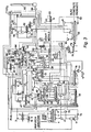
- FIG. 2 a block diagram of a waste- processing method without use of low-pressure moist saturated steam from the heat recovery is shown. Such a variant is necessary when cohoice of the specified steam heat recovery boiler of required parameters is complicated.
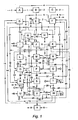
- FIG. 3 a flow diagram of one embodiment of a plant for processing wastes is shown.
- the plant works as follows.
- Known ways and on the known equipment preliminary prepared mixture of crushed municipal or similar refuse with limestone powder (on the circuit it is not shown) moved in the drying installation with heat transfer surface working under underpressure of 2-10 mm of water column (H2O) that excludes allocation of feel unwell smelling gases in an environment.
- H2O water column
- Installation consists of actually the dryer 1 supplied with a casing for the heat-carrier and internal shaft with blades putted on a screw line, a condenser 2 and a fan 3.
- a drum feeders 4 playing a role not only of batchers, but also gas sealers not admitting external air inleakage.
- screw blades provide intensive agitating, uniform warming up, moving along the device and packing of all volume of waste.
- the dryer 1 is warmed with air submitted by a fan 5 from branch of preparation of refuse (on the circuit it is not shown) through an air heater 6 where it is heated up by the final chimney gases of a combustion chamber 7, up to temperature 250 - 260°C (480 - 500 °F).
- air heater 6 where it is heated up by the final chimney gases of a combustion chamber 7, up to temperature 250 - 260°C (480 - 500 °F).
- Such low temperature of air excludes local overheating and premature decomposition in the dryer 1 chlorine-containing organic substances and warming of the dryer through a heating surface excludes contact of refuse and air without its pollution.
- the blowing rate of air is equal to requirement of process of burning in the combustion chamber 7 that provides its the further full use, excludes emission even parts of fulfilled the air in to an atmosphere.
- Water vapor leaving the dryer 1 are condensed in the condenser 2 by turnaround water coming from a cooling tower 8 or the water used for heating and hot water supply of the plant and then by turnaround water of the specified cooling tower 8, condensate gathers in a tank 9 whence by a pump 10 flows to a scrubber 11 on blowing light organic impurity. Noncondenced gases are sucked away by the fan 3 and move in burners 12 of the combustion chamber 7.
- the mix of refuse and limestone is dried up in the dryer 1 up to the intermediate humidity stipulate by quantity of heat brought in by hot air and initial humidity of refuse. Then the mix moves into a mixer-dryer 13 represented by the device in which parallel horizontal shafts with blades putted on a screw line is rotate. The drive of shafts is supplied with the speed rotation regulator. On an output of vapor it is installed the separation device. At rotation of shafts agitating, uniform warming up, transportation and final removal of a moisture from refuse is carried out due to mixing with a part of the solid rests of the pyrolysis leaving a furnace of pyrolysis 14 at temperature 450 - 500°C (840 - 930 °F). After full removal of water the temperature of a mix starts to grow quickly.
- a neutralizer 18 at temperature no more than 110 - 115 °C (230 - 240 °F) that is provided with speed regulation of shafts rotation inside the device.
- Water steam allocated by a dryer are condensed in a condenser 15 by turnaround water coming from the cooling tower 8, condensate moves in an extractor 16.
- Noncondensed gases by a fan 17 go to the burners 12 of the combustion chamber. 7.
- the first stage of pyrolysis is carried out without access of air into the neutralizer 18 which consist of the cylindrical case with branch pipes for an output of pyrolitic gases and the shaft built inside with blades putted on a screw line. Outside the case is supplied with a casing for hot air supply The incoming mix of refuse and limestone first of all is heated up.
- the heat-carrier consumption - the solid rest of the pyrolysis coining from the furnace of pyrolysis at temperature 450 - 500°C (840 - 930 °F) - is adjusted by a drum feeder 19 so that the temperature of a mix in the neutralizer 18 was established 220 - 250°C (430 - 480 °F) that provides full decomposition of chlorine- containing organic components of refuse.
- the furnace of pyrolysis 14 represents a drum rotating furnace with external heating by the chimney gases coming from the combustion chamber 7 located below External and internal surfaces of the drum are supplied with spiral edges that increases a surface of heat exchange and intensifies process of pyrolysis by the shovelling of a material.
- Process proceeds without access of air at temperature 450 - 500 °C (840 - 930 °F).
- pressurization i.e. at superfluous pressure 5-15 mm of H2O created by the fan 23, sending gases of pyrolysis from the neutralizer 18.
- the solid rests of products of pyrolysis are removed from the furnace 14 into the mixer - dryer 13 and the extractor 16.
- the ratio of consumption depends on temperature of a mix in the neutralizer 18 and is adjusted by number of revolutions of drums of the feeders 19 and 26. Washing of the solid rests of pyrolysis in the extractor 16 is carried out by the water circulating through an installation 27 for water treating from heavy metals.
- Water is entered at the opposite end of the device and after passage through all its length leaves through netted baffle plate on intake of a pump 28, the part of water recirculate into a bottom of the device, then to avoid formation of stagnant zones on its bottom.
- Other water with dissolved salts of heavy metals and calcium chloride together with a filtrate from a centrifuge 29 through a cartridge filter 71 by a pump 30 through a heat-exchanger 31 moves in the installation 27 for water treatment from salts of heavy metals in which known, cheap and reliable combined method including water treatment with coal or coke with the subsequent electrocoagulation is used (on the circuit it is not shown).
- Such way allows to remove from water solutions 99.9 % of heavy metals contained in it.
- the solution is warmed up in the heat-exchanger 31 by leaving from the extractor 16 and the centrifuge 29 liquid submitted by the pump 30 and then again goes in the extractor 16.
- the part of the circulating solution (approximately 25 %) by a pump 32 moves in a spray dryer 33 for manufacture of the calcium chloride.
- the solid phase by the rotor device of the extractor 16 is unloading in the bowl centrifuge 29 with automatic screw unloading of a sediment which humidity depending on the division factor of the established centrifuge makes 6 - 15 %.
- the subsequent drying of the damp washed from heavy metals salts and calcium chloride solid products of pyrolysis is carried out in a mixer-dryer 34 due mixing with the hot - 1150 °C (2110 °F) slag leaving from the combustion chamber 7.
- the design of the mixer-dryer 34 is similar to design of the device 13, leaving water vapor are condensed in a condenser 35 by the turnaround water coming from the cooling tower 8, condensate goes to the extractor 16.
- Noncondensed gases by the fan 17 move in the burners 12 of the combustion chamber 7.
- the drained mix of the washed solid products of pyrolysis and slag at temperature 101 - 102 °C (214 - 216 °F) by an elevator 36 and a screw feeder 37 goes to a bunker 38 of the combustion chamber 7 located below the rotating furnace of pyrolysis 14.
- gaseous and liquid products of pyrolysis of refuse are burnt, noncondensed gases from the condenser installations are deodorizing and burning.
- the solid washed out products of pyrolysis basically the carbon, are burning in layer on a moving chain-grate stoker of a direct course 39. Thickness of layer is adjusting by a gate 40. While move in depth of the combustion chamber on slowly movable grate bar surface solid products of pyrolysis are heat up, ignite and burn out then slag is dump into the mixer-dryer 34 and the cooler of slag 20 where it is cooled by air forced by a fan 41.
- the ratio of consumptions of slag in the apparatuses 20 and 34 adjust by position of gates 42 and 43, and, the gate 42 provides such consumption of hot slag at which the temperature of a mix on an output from the mixer-dryer 34 is established 101 -102°C (214 - 216 °F) that indicates about full removal of a moisture from a mixture coming on the grate bar lattice 39 of the combustion chamber 7.
- the initial solution with concentration of 7 - 12 % of calcium chloride (CaCl2) is evaporated in the spray dryer up to 50 - 70 % of concentration and flows down in the screw dryer 52 where due to heat of the chimney gases coming in the beginning in a jacket and then in a screw zone of the dryer itself, it is completely dried up to residual humidity no more than 0.5 % and then goes on cooling in a screw cooler 53 and then unloading in a warehouse of finished goods. Cooling is carried out by turnaround water from the cooling tower 8.
- the moist chimney gases after drying of calcium chloride go to a cyclone 54 where are separated from carried away drops of a solution and by an exhauster 55 moves into the chamber 50 for thermohumid processings of concrete and an installation 56 for manufacturing of carbon dioxide.
- This installation works by the standard absorption - desorption method of reception of carbonic acid from the chimney gases with the help of the monoethanolamine (on the circuit it is not shown). Quantity of the gases coming for manufacturing of carbonic acid and, accordingly, productivity of installation it is limited to thermal balance of system, i.e. that quantity of heat which can be used applying for heating of a desorber of the installations 56 heated up in a heat exchanger 57 high-temperature organic heat-carrier, for example, based on ethylene glycol.
- the chimney gases cleared from carbon dioxide (CO2) by an exhauster 58 are dumped in the common gas flue of final chimney gases of the plant.
- CO2 carbon dioxide
- the content of carbon dioxide in the chimney gases dumped in an atmosphere in comparison with incinerate factories is reduced more than on 64 % because the part of carbon remains in the commodity liquid fuel, the given technology does not use additional fuel and a part of formed carbon dioxide is manufacture as the commodity product.
- Cooled down pyrolitic gas goes in a vertical tubular heat exchanger 61 where its condensation by turnaround water from the cooling tower 8 and in a scrubber - chemisorber 62 for final condensation and clearing of gases and vapors is carried out by an irrigation of its own condensate cooled in a vertical heat exchanger 63 by turnaround water from the cooling tower 8.
- a metering pump 64 from a tank 65 supplied with an anchor mixer automatically under an indication of pH-meter moves a neutralizing solution. Circulation of a condensate is carried out by a pump 66.
- the condensate from the scrubber - chemisorber 62 goes into a separated vessel (oil sump) 67 where it is segregate on water and organic phases which accumulate in corresponding tanks 68 and 69.
- the noncondensed part of pyrolitic gas by a fan 70 goes on burning to the burners 12 of the combustion chamber 7.
- the organic phase of a condensate of a pyrolitic gas from the tank 69 through a cartridge filter 71 by a pump 72 in part goes as fuel to the warehouse of finished goods and in part - to the burning in the burners 12 of the combustion chamber 7.
- the water phase from the tank 68 through the cartridge filter 71 by a pump 73 moves to blow away from light organic substances in the scrubber 11 which is carried out by a part of hot air (- 5 %) supplied by the fan 41.
- the sediment from the cartridge filters 71 periodically during clearing pores filtering elements moves in the combustion chamber 7 (on the circuit it is not shown) .
- the temperature of air delivering in the scrubber is 105 -110°C (220 - 230 °F). Blow off from a great bulk of organic products the water phase from the scrubber 11 by a pump 74 goes on a stage of washing of the solid rests of pyrolysis to the extractor 16. Air sated with organic products and a moisture by a fan 75 moves to mix with the main stream of air leaving the dryer 1.
- the mix of streams goes in the cooler of slag 20 where is heated up to temperature 260 - 270°C (500 - 520 °F), passes through the cyclone 21 and by the fan 22 of hot blasting is dumped in the combustion chamber 7 and a casing of the neutralizer 18. Carried away by stream of air fine particles of slag collected in the cyclone 21 and through the mixer- dryer 34 come back in the combustion chamber 7.
- the drum is installed under angle of 4 - 6° to horizon and rotates with a speed 3- 6 rev/min.
- the motionless end face entrance of the slag cooler and 15 - 25% of the rotating drum length on the part of the input of slag lining by the firebrick with fire resistance not less then 1300 °C (2370 °F), other part is supplied with internal nozzles for pouring slag that helps it shoveling, the best air flow and crushing of the caked pieces.
- slag gets in a scraper conveyer 76 located in the case supplied with surfaces of cooling in which the solution of calcium chloride cleared from salts of heavy metals and turnaround water of the cooling tower 8 circulates cooling slag accordingly down to 65 - 70 °C (150 -160 °F) and 25 - 30 °C (80 - 90 °F).
- the cooled slag cleared of heavy metals and sulfur moves in a bunker 77 whence depending on local conditions is sent to the consumer or to manufacture of the slag concrete products.
- Installation for reception of slag concrete products includes a concrete mixer 78 where move slag and the solution of calcium chloride made by the given technology all necessary components deliver, for example, Portland cement, grinded brick breakages, gypsum, etc. received from extraneous sources.
- the composition of mixes depends on local conditions and can vary over a wide range.
- the received mix goes for modeling and compaction on a vibration platform 79 and then moves in the chamber 50 of thermohumid processing, of concrete products which represents the tunnel with the band conveyer located inside on which the concrete products formed earlier slowly move.
- the drive of the conveyer is supplied with a regulator of speed. Inside the tunnel is waterproofing and heat insulated.
- the floor is made with a bias aside pit for gathering a condensate.
- branch pipes for an exit of chimney gases and in the center - a branch pipe for an entrance of damp chimney gases after the dryers of calcium chloride 33 and 52 in a mix with moist saturated steam from the heat recovery boiler 49 are located.
- Exhausters 80 and 81 mounted on exits of chimney gases are supplied with axial directing devices and two speed electric motors that provides effective regulation of productivity in the big range of loading.
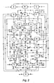
- FIG. 4 a flow diagram of a second embodiment of a plant for processing wastes without the heat recovery boiler for reception of the low pressure moist saturated steam is shown.
- an electric boiler 86 of corresponding productivity connected by system of pipelines on the part of an input of a condensate through the pump 82 with pit of a condensate and on the part of an output of a steam with section of mixting of the chamber 50 of thermohumid processings of slag-concrete products is installing.
- the electric steam boiler 86 is intended for work during start-up and a stop of a plant.
- thermohumid processings slag-concrete products During the established operating mode it is used vapor of the mixer-dryers 13 and 34 and also the extractor 16 which by a fan 87 moves in the chamber 50 of thermohumid processings slag-concrete products. Such decision considerably reduces the power inputs connected to manufacture steam and the consumption of cooling water on condensation of the vapor in the condensers 15 and 35.
Description
- The present invention relates a method and a plant for processing waste, including solid municipal or like refuse and also of the refuse together with oil-industry wastes (oil sludge, acid tars, etc.), soil polluted by pesticides and oil products, waste products of electronics, used tires, all kinds of plastics, sewage sludge of the city waste water treatment plants, the polluted ground sediment of reservoirs, biologically polluted waste products of hospitals, etc.
- Problem of pollution of cities by waste products of the its vital activity and its solution appeared extremely complex scientific - technical and social - economic task. Special specificity here is shown in a possible concentration in these waste products practically all variety of substances and the materials meeting in the nature and is artifcial by created by the human, and also in continuous growth of their quantity.
- Economically the most attractive could be sorting of refuse including on the automated sorting complexes with the subsequent returning of a significant part of components into manufacture. However, it extremely laborious, epidemically and toxically dangerous process allowing to sort no more than 30 % of refuse, as its big part is impossible to separate (Katys M. Dumps of Household Waste Products and Incinerate Factories - Sources of Dioxins. 25-11.2002 20:21/www. svoboda.org).
- Experience of Germany has shown, that recycling is economically expedient only for such materials as ferrous metals, aluminum, glass depending on local conditions, probably, a paper and is completely unacceptable for plastic, packing materials, newspapers, waste products of electronics, linoleum, etc. (Steven P. Reynolds. The German Recycling Experiment and its lessons for United States Policy. Villanova Environmental Law Journal. Vol. V1, 1995, Number 1.). In the USA 30.6 % of municipal solid waste are recovered due to recycling (23.5 %) and composting (7.1 %) (U.S. EPA. Municipal Solid Waste in the United States. 2003 Facts and Figures.). It means, that approximately 70 % of solid waste should be processed by a different way.
- The emergency has developed all over the world and with utilization of oil containing waste products. Till now the comprehensible decision of the challenge - clearing of the ground repeatedly polluted with mineral oil (for example, a ground of territories of the gas stations, seaports, railway depots, tank farms, etc.), recycling of acid tars (waste products of sulfuric purification of some mineral oils, for example, the lubricant oils, containing 15 - 70 % of the sulfuric acid dissolved in water), utilization of ground sediments of oil tanks, ponds - sediment bowls, earthen sludge barns, representing a solid phase, containing paraffins, asphalt-resinous substances, sulfur, sand, clay and other mechanical impurity, and also heavy metals - lead, cadmium, zinc, etc is not found. Such refuse are offered to be processed on units of thermal neutralization where as a result of pyrolysis receive dry carbon containing material - raw material for manufacture of building materials and asphalt concrete mixes, and also the condensate and the gas used as fuel in these units (Zharov O.A., etc. Modern Russian Technologies. Vol. 2. Technologies and the Equipment for Processing and Recycling of Oil containing Waste Products and Oil Sludges. The Directory. Ecoline. Yaroslavl, 2003). It is necessary to note that such solution of a problem is not satisfactory as the solid rests of pyrolysis contain heavy metals and, hence, are not suitable for industrial use and a burial place also demand. Besides extraction oil from ground deposits it is inexpedient in connection with high expenses and insignificant quantity of an oil phase: on the average 5 - 8 %. Most the rational way of the solution of a problem of utilization of the oil sludge is observed at joint process of pyrolysis with municipal solid waste (Muzipov H.N., Nalobova E.V., Shantarin V.D. Utilization of Ground Sediment of Oil Tanks without Waste 21.01.2003 11:29/ www.promeco.hl.ru). Thus, however, the questions associated to protection of an environment from pollution by heavy metals, polychlorinated dibenzodioxins, -furanes and -biphenyls also are not solved.
- Now in the world practice some technologies operate joint thermal processing of municipal solid waste and sludge deposits of the sewage formed on city sewage purification plants. Thus, their joint burning in furnaces of various designs with preliminary drying deposits and obligatory return of chimney gases after dryings on deodorization in a furnace is provided (
U.S. Pat. Nos. 4,753,181 ,5,630,366 ,6,412,428 and Kremer A.I, About Prospects of Joint Thermal Processing of Municipal Solid Waste and Deposits of Sewage. 26.11.2002 22:38/ www.gke.wl.dvgu.ru). In connection with the raised content of heavy metals in sludge deposits of sewage all these technologies result in reception of extremely dangerous slag and ashes which demand a burial place. Besides chlororganic compounds contained in solid waste result in environmental contamination by polychlorinated dibenzodioxins, -furanes and -biphenyls. - Now in the world wide practice it is realized more than ten technologies of processings solid municipal and industrial wastes. The most widespread among them are thermal ways: burning, pyrolysis and gasification.
- Burning cannot be considered as economically reasonable or saving resources method as many organic substances which could to be used, are burnt with additional consumption of fuel - up to 265 π (70 gal) on ton of burnt solid waste (Clarke, M.J., DeKadt, M., and Saphire D. Burning Garbage in the USA. Practice vs. State of Art. Inform Inc. 1991. p. 146-147). Besides existing and offered to use plants for refuse incineration have a lot of lacks the main thing from which is that they at work form secondary extremely toxic waste products (polychlorinated dibenzodioxins, -furanes, and - biphenyls) exude together with heavy metals in an environment with chimney gases, sewage and slag (Marjorie J. Clarke Environmental Scientist Resource Recovery and Waste Disposal Planning. Minimizing Emissions from Resource Recovery. New York City Department of Sanitation. International Workshop on Municipal Waste Incineration. Sponsored by: Environment Canada. Meridien Hotel, Montreal, Quebec. October 1-2, 1987. Second Edition and L A. Fedorov. Dioxins as Ecological Danger: Retrospective and Perspective. M. Nauka, 1993 - 266p /www.seu.ru/cci/lib/books/dioksiny/).
- As at burning waste products it is formed warmth, the desire to use it was natural. So movement:"Waste-to-Energy" has appeared (
U.S. Pat. No. 5,862,762 , Everett: B. Woodruff, Herbert B. Lammers, Thomas F. Lammers. Steam Plant Operation. 7-the Edition. Division of the McGraw-Hill Companies, 1998. and Joseph A. Salvato Nelson L. Nemerow, Franklin J. Acardy Environmental Engineering. 5-the Edition. John Wiley and Sons, Inc 2003. ). However, burning of solid waste with the purpose of reception of heat to manufacture the electric power results in the even greater environmental contamination. It speaks that the electric power consumption is not constant has daily and seasonal peaks that accordingly results in fluctuations of loading of combustion chambers of garbage incineration boilers and, as a result leads to incompletely burn of waste products and to the even greater emission of harmful substances with chimney gases, slag, ash and sewage. For only technical reasons (low-calorie fuel, ineffective generators, etc.) cost of the electric power made on municipal refuse incineration plants cannot compete to cost of the electric power on heat power stations. The price of one kilowatt on heat power stations 1 - 3 cents, and on refuse incineration plants - 11 cents. On laws in force for stabilization of the market to consumers of it is obliged to sell for 2 cents for 1 kilowatt that gives enormous losses for refuse incineration plants and in a combination to necessity of a burial place for slag and ash does these plants absolutely unprofitable, financial forecasts for their development are extremely adverse (The Wall Street Journal. August 11, 1993, p. A1 - A2). - Many companies pass from simple burning refuse to the two-level process including a stage of pyrolysis (decomposition of organic substances without access of oxygen) at rather low temperatures 450 - 800 °C (840 -1470 °F) . Such process appears energetically more favorable than simple burning. As a result of pyrolysis receive gas and the solid rest of pyrolysis. Then those and other products at once without any additional processing send to combustion chamber for burning. The part of gases of pyrolysis after condensation can be removed from system and used as liquid fuel by other consumers (
U. S. Pat. Nos. 4,485,745 and5,669,317 ). Thus the same lacks are observed as at direct burning waste products. In the same cases when gas of pyrolysis is exposed to clearing of acid gases such as chloride hydrogen (HCl), economically process becomes expensive because of application of the expensive equipment and using expensive caustic or calcinated soda and environmental contamination by heavy metals is not eliminated. - Alternative to process of pyrolysis is the process of gasification which goes similarly but at temperature 800 - 1300 °C (1470 - 2370 °F) and at presence of a small amount of air. In this case received gas represents a mix of low-molecular hydrocarbons which then burn in furnace. Such process does not improve an ecological situation whereas presence of air and availability of chlorine organic substances in refuse in combination with high temperature results in intensive formation of dioxins furanes and biphenyls. Salts of heavy metals as well as in other technologies from process are not removing and pollute an environment (
U.S. Pat. No.5,445,087 and the Review of Modern Technologies of Reception of Liquid Fuel from Biomass by Fast Pyrolysis. 06.01.2003 21:59/ www.sciteclibrary.com). - The most complete destruction of the products contained in refuse is carried out during high-temperature pyrolysis or gasification at temperature 1650-1930 °C (3000 - 3500 °F) in volume fused in a mix of mineral additives with metal (
U.S. Pat. No. 5,134,944 ), or at temperature up to 1700 °C (3100 °F) in volume melt of salts or alkalis in a mix with additives and at the presence of catalysts (Ukraine Patent No57984 A - The technology of processing of waste products on a basis of low temperature plasmas at 2000 - 100000 °C (3630 - 180000 °F) is applied basically to small volumes of especially dangerous waste products, for example, biologically polluted waste products of hospitals and differs by the high cost price of processing ($100 per ton of waste products) that-practically excludes a real opportunity to apply this method in large industrial scales (Installation for Medical and Hazardous Waste Treatment Using the AC Plasma - Arc System Soliton - NTT with Institute of Problems of Electrophysics. http://soliton.msk.ru/hazard.html 12.21.2002).
- Concentration of oxides of heavy metals in slag and ashes in 2 - 3 times (sometimes and more) is higher some heavy metals than in burnt solid waste. Therefore, though thermal methods allow to reduce considerably volume of waste products, thus ashes even more dangerous to an environment and the slag requires special measures on recycling or a burial place are formed (Yufit S. S. Incinerate Factories - Rubbish Heap in the Sky. Ecoline, 1998). For processing of toxic slags the technology of ecological concreting is used: mixture of slags after their neutralization with cement, lime or dioxide silicon with the subsequent hardening a mix. At correct mixing waste products with the cohesive agent occurs original "incapsulation" toxic substances (including heavy metals and dioxins) in the cement stone which is not passing toxic substances into an environment. (
U.S. Pat. Nos. 4,120,735 ,4,518,508 ,5,286,430 ,5,466,407 ,5,649,894 and6,342,461 ). However, such technology requires preliminary neutralization of waste products for what a plenty of chemical reagents is necessary. A number of the substances making waste products, for example, sulphur-containing can cause degradation of a cement stone that results in diffusion of contamination into an environment. Besides, toxic metals in the certain conditions can be washed away from blocks by rains, for example, at change of acidity of rain water according to "weather conditions" (Yufit S.S. Incinerate Factories - Rubbish Heap in the Sky. Ecoline, 1998). - The advanced method of ecological reconcreting - the integrated mineral-matrix technology should provide ecological safety of a received material due to chemical banding of contamination down to their inclusion in a breaker plate cementing new formation (for example, heavy metals) or blocking of contaminators by colloid- disperse and sol-helium phases in mass of a forming material. (
U.S. Pat. Nos. 4,726,710 ,4,741,776 and4,872,954 ). However, it is possible only at rationally picked up components of system when potential chemical properties of components of system and their mechanical characteristics are summarized (Knatko V.M., Knatko M.V., Scherbakova E.B. IMM - Technology Against Waste Products. /lmitation of Natural Processes of Mineral Formation - a Perspective Direction of Neutralization and Recycling of Industrial Wastes. Energy: Economy, Technique, Ecology. - No 12, 2001, p. 29-35). Commercially such condition cannot be executed as structure of municipal refuse and accordingly slag is not constant. Thus, even the advanced technologies do not provide manufacture of non- polluting, suitable for slag further use. Cost of slag burial place is ten times higher than a burial place for municipal refuse. - It is necessary to note that in all patents which have been mentioned above hardening of slag-concrete mixes it is stipulated at usual temperature of surround air that is the extremely irrational because it takes too long time and reducing forms turnaround delays release of finished goods. For acceleration hardening of concrete and increases physico - mechanical parameters of products apply thermohumid processing - steaming in chambers by the wet saturated steam which creates the thermal and damp inert environment, favorable for hardening of concrete. Modes of steaming are various and depend on structure of concrete mixes, the optimum temperature isothermal concrete warm up is 80 - 85 °C (175 - 185 °F) , that provides for 8-20 hours the same durability which concrete obtains in the age of 28 day (Bazhenov Y.M. Concrete Technology. Moscow, 1978, p. 205 - 229).
- However, such way of reduction of a production cycle, increase physico - mechanical parameters of products provides significant expenses for construction and operation of boiler-houses, the big charge of the steam reaching 1,2 τ on 1m3 concrete and, accordingly, of water and fuel (Dmitrovich A. D. Heat and Mass Exchange at Hardening of Concrete in the Steam Environment. Moscow, 1967).
- The fact of fuel production by pyrolysis of waste products is extremely important. In many cases it possible to replace oil fuel, or to use a mix of them. All known processes provide preliminary sorting and classification of waste products with the subsequent pyrolysis of an organic part in various temperature ranges: 200 - 600 °C (390-1110 °F) (
U.S. Pat. No. 5,114,541 ), 315 - 565 °C (600 - 1050 °F) (U.S. Pat. No. 4,153,514 ), 400 - 870 °C (750 - 1600 °F) (U.S. Pat. No. 4,063,903 ), 430 - 730°C (800 -1350 °F) (U.S. Pat. No. 4,077,847 ) and burning of the solid rest of pyrolysis in furnace of various designs. All these processes, however, lead to environmental contamination by toxic salts of heavy metals and are not suitable for processing the waste products containing polyvinyl chloride and other chlorine-containing plastics in connection with formation of polychlorinated dioxins, furanes and biphenyls. Besides after separation of a condensate of pyrolitic gas on fuel and water phases, enough complex water treating before its dump into the water drain is necessary. - The way of three-stage burning developed for coal-fuel oil mazut and coal-dust boilers by Japanese companies Mitsubishi Heavy Industries, Inc. and Hitachi - Zosen (Development of MACT - in Furnace NOx- Removal Process for Utility Steam Generators / Y. Takahashi e. a. // Proceeding of the American Power Conference. 1982. Vol. 44, p. 402 - 412 and Three - Stage Combustion System for Pulverized Coal Developed for Commercial Use / Y. Sekiguchi e. a. // Hitachi - Zosen Technical Review, 1982. Vol. 43, p.95-104) and also of three-stage burning for combustible solid waste is known. (
U.S. Pat. Nos. 5,205,227 and5,307,746 ). These methods allow to lower considerably emission of nitrogen oxides, however, thus its require careful preliminary sorting of municipal refuse because the methods are unsuitable for burning the waste products containing linoleum, plastic, batteries, accumulators and other materials including chlororganic substances and heavy metals as thus slag and final chimney gases contain highly toxic dioxins, furanes, biphenyl and heavy metals. - By development of modem economically effective technologies of thermal processing municipal and similar waste products are necessary for achieving the maximal recycling of secondary power resources and first of all for preliminary heating and drying highly the damp and frozen together waste products.
- In
U.S. Pat. No. 4,859,177 the furnace for burning combustible waste products which rotational device is divided into a zone of drying and a zone of burning is submitted. Such integration of zones in one device provides economy of capital expenses at construction. However, optimum work of the furnace is possible only at receipt of waste products of constant humidity when recirculation degree of the final chimney gases in the rotational device and temperature in a zone of burning of the furnace are balanced and constant. In case of submission highly the damp or frozen waste products, and also waste products of variable humidity burning becomes unstable, chemical incompletely burn waste products and, accordingly, the charge of fuel and emission of harmful substances in an atmosphere and with slag sharply grows. - In Russian Patent No. model -
35,257 - In
U.S. Pat. No. 5,052,313 ,5,080,581 and5,285,581 is described the way of processing of waste products of the high humidity including preliminary dehydration in the mechanical device with the subsequent heating and drying in a multisection dryer by final chimney gases of furnace in the beginning without contact of environs, and then at direct contact of chimney gases to waste products. The liquid educed from waste products in the mechanical device, concentrates in the evaporator due to recycling of heat leaving of a dryer gas-vapor mixture, the concentrate goes to a dryer, chimney gases after clearing in a scrubber are dumped in a chimney. Such method allows to save fuel and to receive a wide range of in regular intervals dried up waste products before their feeding on burning. However, it is impossible, to process of the waste products, containing salts of heavy metals and chlorine organic substances as it is impossible to prevent dump them into an atmosphere and with slags polychlorinated dioxins, furones, biphenyls and salts of heavy metals, and the condensate received after cooling of gas-vapor mixture of a dryer in needed complex clearing before dump into the water drain. - In
U.S. Pat. No. 5,231,936 . is described drying and burning of high damp combustible waste products. Drying is carried out by final chimney gases of furnace. The air from the bunker of initial refuse by the fan moves as blasting in furnace for burning waste products that simultaneously destroys a part of feel unwell smelling gases. Drying by final chimney gases reduces the discharge of fuel, however, direct contact of environs results in pollution of chimney gases by feel unwell smelling and other harmful substances which then together with chimney gases are dumped in an atmosphere because the cyclone established before a chimney, entraps only a dust and soot substances. - In
U.S. Pat. No. 4,542,703 unit for burning waste products of any humidity is described including subsequently positioned on the gases flow furnace of drying and burning of waste products and the afterburning of chamber of products of incomplete combustion. Waste products move in an end face of the rotating furnace opposite to a burner and move towards to a stream of gases that provides in the beginning their drying, and then and burning. Slag is unloaded from the furnace in area of location of a burner, and chimney gases go in the afterburning chamber which burner provides a spiral stream of gases inside the chamber at temperature 1200 °C (2190 °F). The afterburning chamber is established with the purpose of reduction of concentration of products of incomplete combustion including dioxins contained in final chimney gases of the furnace that would enable to burn plastics and toxins. However, in the Commoner's work (Commoner B. et al. Waste Management and Research 5:327 - 346, 1987) it is informed that at inspection of incinerators has been established that dioxins are formed during burning and that formation of them occurs also in a zone of cooling, therefore rise in temperature at burning does not result to destruction of dioxins. It is established that emissions of products of incomplete combustion from a different sort of furnaces of burning do not decrease at change of temperature from 700°C up to 1600 °C (1290 - 2910 °F) (Trenholm A., Thurnay R. Proceedings of the Thirteen Annual Research Symposium. Cincinnati, OH: U.S. EPA Hazardous Waste Engineering Research Laboratory,EPA/600/9 - 87/015, Jule 1987 - In
U.S. Pat. 4,292,742 is presented the plant of preliminary drying of burnt fuel by the impoverished oxygen gas or other inert gas, for example, by nitrogen. The system of drying of fuel represents the circulating contour included a heater of air with the fluidized bed of cooled slag, a dryer with the fluidized bed of dried up fuel, the cyclone, the filter and the fan connected among themselves by system of pipelines. Effective work of such plant is possible only for homogeneous in composition of a dried up material, for example, fuel. At processing non-uniform, complex waste products in composition what the municipal refuse is the high degree of ablation of light particles (a paper, a film, etc.), i.e. short time of their stay in the fluidized bed of a dried up material that will result to final high moisture content of refuse, to fast plug up of the cyclone, the filter and the condenser a damp material, a stop of a plant on clearing will be observed. - In
U.S. Pat. No. 5,762,010 the way of processing of waste products of any humidity providing preliminary heating of the intermediate heat-carrier (the ceramic spheres used simultaneously and as the crushing agent) is described, due to utilization heat of process of pyrolysis with the subsequent separation of ashes from spheres in the punched part of a drum-type dryer. Then the specified spheres at temperature 750°C (1380 °F) mix up with initial waste products and dry them with simultaneous heating of air submitted in a casing of a dryer. Exuded from waste products steam mixes with hot air and moves to heat the initial waste products. The part of the received gas of pyrolysis without additional processing goes to furnace to the burning, final chimney gases heat up other part of gas of pyrolysis to temperature 750 °C (1380 °F) which moves in the chamber of gasification for pyrolysis of waste products. Surplus of gas of pyrolysis is burnt in burners on open air. However, this way is suitable only for processing of industrial residue with the content of dry substances no more than 10 % when formed ashes is easily kibble by spheres and then is eliminating on screens. At processing of municipal waste products stable fine grind formed slag and, accordingly, its separation on screens from spheres is impossible that will result in an often stop of the equipment for cleaning. Use of surplus of gas of pyrolysis is not stipulated as commodity fuel therefore it is all burnt for nothing in burners at open air that in addition ally pollutes an environment, chemical neutralization of steam condensate of dryer before its dump in the water drain is necessary. Besides at processing the waste products containing chlororganic substances and heavy metals, environmental contamination by dioxins, furanes, biphenyls and salts of heavy metals is inevitable. - In
U.S. Pat. No. 4,797,091 preliminary drying of an organic part of sorted crushed waste products before hauling in a pyrolysis reactor by air which has been heated up due to recovery of heat of slag leaving of the rotational furnace is provided. The system of drying of waste products represents the circulating contour including a cooler of slag, a crusher of waste products, a pneumatic dryer and a cyclone connected among themselves by system of pipelines. Drying of waste products is carried out by direct contact to hot air in a vertical pipe of a pneumatic dryer. However, because in plant removal of a moisture from the heat-carrier or preliminary heating of cold damp refuse is not provided, at their direct contact the temperature of air can be reduced up to temperature of a dew-point what will result in drainage of air due to loss of a condensate and, accordingly, to humidifying instead of drying of refuse. In case of increase of the flow of the hot air what excluding its cooling up to a dew-point consumption of the electric power for blasting sharply increases what is inherent in work of pneumatic dryers. Besides, to adjust duration of drying and final moisture content of dried up refuse is practically impossible. Thereof into reactor of pyrolysis enters non-uniformly dried up waste products that, accordingly, results in the overexpenditure of fuel in pyrolysis process. - Thus, the problem of preliminary drying municipal and similar waste products before its delivery for thermal processing has no satisfactory solution.
- In
U.S. Pat Nos. 4,353,713 ,4,448,558 and4,597,771 are described processing of coal together with light fraction of the municipal solid waste including preliminary sorting and crushing of the specified waste products their mixing with limestone, pyrolysis of the received mixture with the subsequent clearing of pyrolitic gas, allocation of some products, burning of the rest and use of heat of exothermal reactions between limestone or dolomite and dioxide of carbon. These processes, however, lead to environmental contamination by toxic salts of heavy metals and are not suitable for processing of waste products of plastic, despite that limestone or dolomite could neutralize discharged at decomposition of plastic hydrogen chloride (HCl). It speaks that chloride calcium received at such neutralization (CaCl2) in conditions of high temperature in gasifier 650 - 980°C (1200 - 1800 °F) is in the melted condition (the temperature of melt of CaCl2 is 737 - 747 °C (1358 - 1376 °F) that results in sintering and lumping of processable waste products, to sharp decrease of efficiency of contact of environs and in a combination to weak hashing does process of neutralization of hydrogen chloride absolutely not effective and, hence, practically excludes an possibility of processing of plastic. The high temperature in furnace 1090 - 1315 °C (2000 - 2400 °F) results in the fused condition of salts of heavy metals, in general chlorides and sulfates, (temperature of fusion 242 - 915 °C (467 - 1678 °F), and, above their surface exist taking place in balance with these melts their steams. As partial pressure of steams these salts is not enough, they in weight of chimney gases are carried away from the furnace in a chimney, and, due to low concentration to allocate them from gases it is practically impossible though their total represents a vital issue. In slag also there are salts of heavy metals that excludes an opportunity of its further use. - In
U.S. Pat. No. 6,202,577 is shown processing of municipal and similar waste products including removal from them large metal objects crushing and mixing with limestone. Pyrolysis of the specified mixture is carried out in two stages. The first stage - in the mixer located in the furnace, at temperature 240 - 260°C (460 - 500 °F) due to heat recycling of part of the solid rest of pyrolysis when chlororganic compounds which are taking place in refuse, decay with allocation of hydrogen chloride (HCl) which reacts with crushed limestone and thus is lead out from process. The second stage is carried out at temperature 450 - 500°C (840 - 930 °F) due to utilization heat of the chimney gases received in combustion chamber located below. Thus polychlorinated dioxins, furanes and biphenyls in volume of the furnace are not formed because all chlorine has been removed from processable refuse at the previous stage of pyrolysis. Gas allocated during pyrolysis is condensed, the organic phase of it, is liquid fuel and goes together with noncondensed gases in combustion chamber. The water phase feeds on a stage of washing out salts of heavy metals and calcium chloride (CaCl2) which formed at neutralization of hydrogen chloride (HCl). The washed out part of solid products of pyrolysis after drying by mixing with hot slag feeds in combustion chamber on burning. As a result received slag not containing heavy metals and sulfur. The presented way has a number of essential lacks: - 1. Process of preliminary drying of initial municipal refuse is not anticipated. It is known that process of pyrolysis begins only then when water is completely evaporated and temperature has achieved critical value at which decompose of organics contained in the refuse takes place. This period depends of humidity of initial refuse can take up to 30 - 40 % of length of all path of a material in the furnace of pyrolysis. Thus, presence of a moisture in refuse results in increase in time of presence of waste products in the furnace of pyrolysis that essentially reduces its productivity, results in the overspend of fuel and, accordingly, reduction of an out put of commodity fuel.
- 2. The municipal refuse contains different objects and materials including glass, the temperature interval of beginning of its softening depending on composition is equal 400 - 600°C (750 - 1110 °F). Thus, cooling of slag by air which temperature is below specified will result in glass-transition and slagging of slag cooler and, accordingly, in stop of work of all factory. Slag cooling at higher than the specified temperature the significant part of heat is losing what results in the overspend of fuel in combustion chamber and, accordingly, to reduction of an output of commodity fuel.
- 3. The washed out solid products of pyrolysis after a scrubber have high humidity that causes the big consumption of hot slag for their drying in the mixer before feeding on burning. As a result in combustion chamber recycling the significant amount of slag which to ballast combustion chamber what complicates burning out combustible components of a solid product of pyrolysis, results in the overspend of fuel and, accordingly, reduction of an output of commodity fuel.
- 4. Manufacture of finished articles from slag is not stipulated what considerably reduces economic parameters of work of a plant.
- 5. At use of limestone during pyrolysis of municipal refuse alongside with its interaction with hydrogen chloride it is impossible to exclude and interaction with organic acids. Therefore to expect reception of organic acids including acetic, ant, metactonic, oil, etc. in essential quantities it is impossible. In this connection instead of reception of organic acids it is more rational to organize manufacture of liquid hydrocarbonic fuel.
- 6. The water entered together with damp refuse is processed during the process. Due to evaporation of a plenty of water in dryers of calcium chloride and dump water steams together with final chimney gases into an atmosphere the given technology has no sewage, however, the significant amount of fresh water is needed on additional adding water to turnaround system of cooling and cooling of slag before its sending to the consumer.
- 7. During neutralization of hydrogen chloride by limestone in the furnace of pyrolysis calcium chloride is formed which then together with salts of heavy metals is extracting by washing water. After drying a part of this solution receive dry calcium chloride together with a concentrate of salts of heavy metals. Such mix is not a commodity product, it is necessary to provide their separate manufacture.
- 8. Their complex and expensive preliminary clearing of harmful impurity (acids, sulfuric compounds, etc.) is necessary for producing of liquid carbonic acid from gases of pyrolysis by chemical sorbents with the subsequent clearing gas in electrofilters or by compressing up to high pressures with the subsequent condensation and separation of impurity that does production of carbonic acid economically not the favorable enterprise and, accordingly, does not reduce emission of carbon dioxide (CO2) into an atmosphere.
- 9. The joint burning in combustion chamber liquid fuel, noncondensed gases of pyrolysis and solid products of pyrolysis is executed not rationally what leads to significant emissions of nitrogen oxides in an atmosphere.
- 10. Direct contact between washing water and noncondensed gases of pyrolysis in a scrubber due to a difference in partial pressure of light organic substances in water and gas in the beginning results in enrichment by organic substances of the gas phase feeding in combustion chamber, i.e. to blowing waters from light organic substances. Then taking into account that the quantity of these gases is not enough and also that in them due to ablation in separated vessel products of incomplete condensation of organic substances will collect that will result in receipt in dryer of calcium chloride the water phase with the raised contents of organic substances and, accordingly, will start the emissions of organic substances in a chimney and an environment
- 11. For carrying out the process of pyrolysis the rotating drum furnace including built - in devices for return of a part of a solid product of pyrolysis in the beginning of process and its mixture with again acting mix of waste products with a limestone is used. Such complex design of the furnace creates difficulties while in service including to stops on cleaning and repair.
- Thus, for creation of the advanced highly effective technology and a plant for processing municipal and similar waste products it is necessary to exclude all lacks specified in the previous patents.
- The purpose of the invention - to create economically effective the method and plant for processing of wastes including a solid municipal or like refuse and also together with it earlier specified waste products due to manufacture of non-polluting commodity products: liquid fuel, dry calcium chloride, liquid carbonic acid, a concentrate of salts of heavy metals and slag- concrete products for the building industry.
- The following purpose of the invention - to exclude emission in an environment of organic light flying and feel unwell smelling substances, carbon monoxide (CO) and salts of heavy metals, including radioactive, to reduce emission of carbon dioxide (CO2) and nitrogen oxides (NOX), to exclude formation of highly toxic polychlorinated benzodioxins, -furanes and - biphenyls by removing of air from the preparation block of waste products and its use at the first stage of drying of initial waste products under underpressure with submission of noncondensed gases in combustion chamber, blowing of condensates by the hot air feeding then also in combustion chamber and burning in volume of combustion chamber in three stages, extraction salts of heavy metals from a solid product of pyrolysis, neutralization in the first stage of pyrolysis of evolving hydrogen chloride by limestone.
- The following purpose of the invention - to increase an output of commodity liquid fuel due to reduction of its use on own needs by deep recycling secondary waste heat of slag, a solid product of pyrolysis, pyrolitic gas, final chimney gases of combustion chamber and dryers of calcium chloride, centrifugal separation of the solid product of pyrolysis washed in an extraction unit.
- The following purpose of the invention - to provide effective preliminary drying of municipal and similar waste products of any humidity including frozen together by two-phases drying - in the beginning with the hot air which has been heated up due to utilization of heat of final chimney gases of combustion chamber after heating by them the furnace of pyrolysis and then mixing with a part of a solid product of pyrolysis.
- The following purpose of the invention - to carry out separate manufacture of a concentrate of salts of heavy metals and dry calcium chloride by consecutive elicit salts of heavy metals from washing water after an extractor at first, for example, by sorbents and electrocoagulation, and then calcium chloride in dryers due to utilization heat of final chimney gases of combustion chamber.
- The following purpose of the invention - to reduce a production cycle, to improve physico-mechanical parameters of slag-concrete products by thermohumid treatment by final damp chimney gases of dryers of the calcium chloride finishing as far as 100 % relative humidity by moist saturated steam of low pressure from the heat recovery-boiler or of the vapor of corresponding technological equipment.
- The following purpose of the invention - to reduce the consumption of water for technological needs due to return to manufacture the condensate received at condensation of a moisture from damp chimney gases after dryers of calcium chloride cooled before production of carbon dioxide and from the chamber of thermohumid treatment of slag concrete and also use of part of the made solution of calcium chloride for setting acceleration and hardening of concrete with corresponding decrease of the amount of water for concrete batch.
- The following purpose of the invention - to exclude a stop of a plant for clearing and repair in connection with slagging of a slag cooler and breakage of the recycling mechanism of pyrolysis furnaces by installation a rotating drum cooler of slag and pyrolysis to make in two stages in consistently established neutralizer and the drum furnace of the pyrolysis connected among themselves by way of a product by elevator and screw feeder and on a path of gases of pyrolysis by the pipeline with the fan providing direct-flow movement of environs in the furnace of pyrolysis.
- More detailed explanation of mentioned above and other purposes and advantages is submitted in the detailed description of the invention together with accompanied drawings.
- Thus, the offered technology provides manufacture of non-polluting commodity products is based on thermochemical processing of wastes (pyrolysis) and does not require their preliminary sorting. However, taking into account experience of Germany, local conditions and economic reasons it is useful to allocate preliminary with known ways objects which recycling is expedient, for example, ferrous metals, aluminum and glass though the technology of it does not demand it.
- During process such highly toxic substances as polychlorinated dibenzodioxins, -furanes and -biphenyls are not formed, and salts of heavy metals, including radioactive, instead of emission in an environment gather as a concentrate. Atmospheric discharge of carbon monoxide (CO) is excluded, organic light flying and feel unwell smelling substances is excluded too, emission of carbon dioxide (CO2) is reduced in comparison with working plants on 64 %, and nitrogen oxides (NOx) - on 60 %.
- The recycling system of heat carried out in productions is maximized so that provides the coefficient of useful consumption of heat energy of a plant of 93,5 % that together with manufacture of own fuel allows not only to refuse to use of fuel from the outside, but also to expose the stayed quantity on the market. Only during start-up period of a plant it is necessary to use earlier made fuel or fuel from extraneous sources.
- All stages of process are not toxic, not fire hazardous and explosive. Process is continuous also is fully automated, allows to process effectively waste products of any humidity including frozen together.
- There are no liquid and solid secondary waste products as water and the water solutions formed in process are processed during the process and the slag cleared of heavy metals and sulfur is used in manufacture slag-concrete products Production waste are only chimney gases which not containing highly toxic components. Besides in connection with application of thermohumid treatment and depending on composition in 30 - 80 times are reduced hardening time of concrete mixes, increase of physics - mechanical parameters of slag concrete products. Thus the consumption of fuel is excluded due to heat utilization of final chimney gases combustion chamber and dryers of calcium chloride.
- Capacity of the plant can vary within a wide range of parameters because it consist of separate technological lines in which the standard series-produced equipment is used only.
- As a result of the calculations it is established, that at processing of one ton of municipal refuse of average composition the following commodity products are manufacturing: 110 kg of liquid fuel with heat value about 8100 kcal/kg (14,500 Btu/lbm), liquid carbon dioxide and dry calcium chloride (more than on 30 kg of each product), up to 6 kg of a mix of salts of heavy metals and coke or coal (150 g actually salts), up to 300 kg of slag not containing a harmful impurity.
- Liquid fuel is used for heating buildings and in power boilers, Liquid carbon dioxide - for carbonation of beverages, in welding practice, etc. Calcium chloride is applied to acceleration of concrete hardening, as deicer for roads, railway switches, regelation of coal and ores, at preparation of refrigerant, medical products and in an agriculture. Heavy metals is raw material for a metallurgical industry. The slag cleared of heavy metals and sulfur is used in road construction and at manufacturing of slag concrete products.
- An advantageous embodiment concerns a plant for processing of wastes comprising the steps of:
- 15.1 a dryer with heat-transfer surface supplied with a casing for the heat-carrier, internal shaft with blades mounted on a screw line for mixing, moving and tightening of pyrolysis mixture, the drum feeders installed at input and output of the specified mixture, an additional branch pipe with the regulating gate for submission of acid tars, connected by system of pipelines from the part of an output of vapor with condenser installation, an input of the heat-carrier - with the air heater installed in chimney of final chimney gases of a plant, and from the part of an output- with the fan feeding an air in a scrubber for blow away a condensate from an impurity the organic substances and the cooler of slag located below combustion chamber;
- 15.2 a condenser installation for vapor of a dryer supplied with the condenser, the fan, the tank of a condensate and the condensate removal pump connected by system of pipelines on the part of an input of vapor with a dryer, an output of a condensate - with a scrubber to blow away of a condensate from an impurity of organic substances by air coming after heating of a dryer, and an output of noncondensed gases through the fan with burners of combustion chamber;
- 15.3 a mixer-dryer supplied with parallel horizontal shafts with speed rotation regulator and blades mounted on the screw line carrying out final drying of specified pyrolysis mixture due to mixes with a part of the solid rests of pyrolysis and connected by the pipeline with a drum feeder on the part of an input of the solid rests of pyrolysis with the furnace of pyrolysis, system of pipelines for pyrolysis mixture on the part of an input with a dryer, on the part of an output of the drained mixture with neutralizer, on the part of steam output- with the condenser and an extractor, and noncondensed gases - through the fan with burners of combustion chamber;
- 15.4 an installation for washing other part of the solid rests of the pyrolysis leaving the rotating furnace of pyrolysis supplied with the extractor which body keeps on a branch pipes of input and output of the solid rest of pyrolysis and washing water, output of vapor and an input of a condensate, an internal shaft with blades mounted on a screw line for mixing and movings of a product to a countercurrent to coming washing water and rotating device for a unloading of the washed rests of pyrolysis, pumps, the condenser, the fan and a settling centrifuge with an automatic unloading of the deposit connected by system of pipelines thus, that the extractor an input of the rests of pyrolysis connected through a drum feeder to the furnace of pyrolysis, and on an output - with a centrifuge, on an output of vapor - with the condenser, the condensate from which again comes back in an extractor, and noncondenced gases by the fan move in the burners of combustion chamber, and, the centrifuge via line of filtrate through the pump and heat exchanger is consistently connected with installation for clearing of liquids from heavy metals and with an extractor, and via line of deposit - with the mixer-dryer installed under a furnace;
- 15.5 a neutralizer supplied with branch pipes for an output of gases of pyrolysis, a casing for feed of hot air and the shaft built in inside with blades mounted on the screw line providing the first stage of pyrolysis with simultaneous neutralization of hydrogen chloride and reception of the calcium chloride connected on the part of an input of pyrolysis mixture with the mixer-dryer, on an output - through elevator and screw feeder with the rotating furnace of pyrolysis, and, branch pipes of an output of pyrolitic gas by system of pipelines through the fan are connected to the furnace of pyrolysis, branch pipes of a casing on an input of air are connected with the forced draft fan and on an output - to a cooler of stag;
- 15.6 a furnace of pyrolysis of the organic products contained in pyrolysis mixture supplied with a rotating drum with external heating by chimney gases of combustion chamber, external and internal ribbing surfaces, motionless loading and unloading the end faces connected on the part of an input with a screw feeder of a mixture and with a forced draft fan of gas of pyrolysis from neutralizer, on an output of the solid rests of pyrolysis through drum feeders with the mixer-dryer and an extractor, moreover on an output of chimney gases and gas of pyrolysis with the cyclones connected on an output of a dust of a product with a specified screw feeder;
- 15.7 a combustion chamber blocked with the furnace of the pyrolysis located below specified furnace and supplied with a moving chain-grate stocker for burning the washed out solid rests of pyrolysis, the burners located above of a grate bar surface for burning of liquid and gaseous products of pyrolysis and noncondensed gases, during start-up of a plant - reserve fuel and also air nozzles of the sharp blasting located above burners;
- 15-8 a condenser installation of the pyrolitic gas supplied with connected by the system of pipelines the cyclone, the heat exchanger for heating of the high temperature organic heat- carrier, the tubular condenser, the scrubber-chemisorber, the separated vessel, the tubular heat exchanger for condensate cooling, the circulating pump, the collecting tanks for water phase and organic fuel, the cartridge filters, the pump for feeding of a water phase in a scrubber for to blow away of organic impurity, the pump for feeding of liquid organic fuel in burners of combustion chamber and a warehouse of finished goods, the fan for feeding of noncondensed gases in burners of combustion chamber, and, at infringement of a technological mode for neutralization of acidic impurities anticipated installation of a tank with a mixer and the metering pump of neutralizing solution;
- 15.9 an installation for blowing away of the water phase of condensed products pyrolysis from the organic impurity, supplied with a scrubber filled with put on rings, the pump and the fans connected by system of pipelines at an input of hot air through the fan with a dryer, at an output through the fan with a cooler of slag, at an input of a water phase with condenser installation of a pyrolitic gas, and at an output through the pump with an extractor;
- 15.10 an installation for heat utilization of the final chimney gases supplied consistently connected with chimney a cyclone, air heater with the fan for air feeding, exhauster and the heat recovery boiler for moist low pressure saturated steam production connected at the input of chimney gases with the furnace of pyrolysis, and at the output with installation for reception of calcium chloride, and, the cyclone at an output of a dust is connected with a screw feeder of the furnace of pyrolysis, air heater at the input of air through the fan is connected to a place of preparation of waste products, at the output with a dryer, and the heat-recovery boiler is connected by a steam line to the chamber of thermohumid processings of slag concrete;
- 15.11 an installation for feeding of the moist saturated steam in the chamber of thermohumid processings of the slag concrete replacing in case of complexity of a choice serially manufacture heat- recovery boiler of required productivity and supplied with the electric steam boiler connected by the system of pipelines at the input of a condensate and an output of steam with the specified chamber of processing of slag concrete and the fan connected at the input of steam with pipelines for vapor of mixer-dryers and an extractor, and at the output of steam - with the specified chamber of processing slag concrete;
- 15.12 an installation for manufacturing the calcium chloride supplied with a spray and a screw dryers, a a screw cooler, exhausters and a cyclone connected by system of pipelines in such a manner that drying of a solution of calcium chloride is carried out due to heat utilization of final chimney gases in two stages: in the beginning in a spray, and then in a screw dryer with the subsequent cooling in a screw cooler, and, the consumption of the chimney gases, feed by the exhauster simultaneously in a spray dryer and a screw dryer is supported automatically by system of the streams ratio block, and final moist gases are released from drops of a solution in a cyclone and move to the installation for reception the carbon dioxide and to the chamber of thermohumid processings of slag concrete;
- 15.13 an installation for reception carbon dioxide from the chimney gases supplied with the equipment using a method of reception carbon dioxide with the help of the monoethanolamine, connected by system of pipelines at the input of the heating agent with the heat exchanger for heating of the high temperature organic heat-carrier, the scrubber - cooler of chimney gases before an absorber of the installation is connected by condensate pipe with cooling tower of plant and the exhauster of final gases - with chimney of final chimney gases of a plant and a chimney;
- 15.14 a mixer-dryer of the washed and filtered solid rest of the pyrolysis supplied with parallel horizontal shaft with blades put on the screw line carrying out drying the specified rest of pyrolysis due to mixing with other part of hot slag of combustion chamber and connected at the input with a centrifuge and through the gate with the combustion chamber, and at the output through an elevator and screw a feeder with the bunker of a combustion chamber, an output vapor - with the condenser and an extractor, and noncondensed gases through the fan - with burners of the combustion chamber;
- 15.15 an installation for cooling the slag supplied with the rotating drum cooler of slag which entrance part lining by the firebrick and connected through the gate to combustion chamber, other part of the drum has internal nozzles and steel or ceramic spheres for shoveling and crushing of slag, the scraper conveyer located in the case having surfaces of cooling and the bunker of the cooled slag, and, the drum cooler in a countercurrent to movement of slag is connected at an input of air through the fan with the dryer, at an output through the cyclone with the forced draft fan, surfaces of cooling of the conveyer are connected to the pipeline of the calcium chloride solution cleared of heavy metals and to turnaround system of cooling tower and the bunker of the cooled slag - with a warehouse of manufacture goods and with installation for reception of a slag concrete;
- 15.16 an installation for reception of a slag concrete products supplied with a concrete mixer for reception of a concrete mixture of necessary composition, a vibration platform for modelling and compaction of the specified mixture, exhausters, a condensate removal pump and the chamber of thermohumid processing connected by system of pipelines at an input of the heat-carrier with installation for reception of calcium chloride and the heat recovery boiler, at an output through exhausters with chimney of final chimney gases of a plant and a chimney, and at an output of a condensate - through a condensate removal pump with turnaround system of water supply of cooling tower and an extractor.
- Furthermore, it is possible that in step 15.1 the drum feeders simultaneously with regulation of the consumption of pyxolysis mixture exclude external air inleakage in working volume of a dryer. Additionally, it is possible that in step 15.2 condenser installation ensures the functioning of the dryer with heat-transfer surface under necessary underpressure 2-10 mm of H2O Furthermore, it is possible that in step 15.3 the temperature of the drained mixture at an output from the mixer-dryer is no more than 110-115 °C (230 - 240 °F) and is established due to speed regulation of shaft rotation inside the device. Additionally, it is possible that in step 15.3 and 15.4 the ratio of the consumptions of the solid rests of pyrolysis in the mixer-dryer and an extractor it is adjusted by the drum feeders established at an output of the solid rests of pyrolysis from the rotating furnace of pyrolysis so that pyrolysis temperature of a mixture in neutralizer is established at a level 220 - 250 °C (430 - 480 °F). Additionally, it is possible that in step 15.5 the forced draft fan sends hot air at temperature 260 - 270 °C (500 - 520 °F) to a casing of neutralizer only for compensation of losses of heat into an environment. Additionally, it is possible that in step 15.6 the fan of sending of pyrolysis gas of from neutralizer ensures the functioning of the furnace of pyrolysis under necessary pressurization of 5 - 15 mm of H2O. Additionally, it is possible that in step 15.7 regulation of the consumption of air sending in burners located above a grate bar surface of lattice is corrected depending on the content of nitrogen oxides (NOX) in final chimney gases of combustion chamber. Additionally, it is possible that in step 15.8 at infringement of a technological mode clearing of gases and vapors from the acid impurity is carried out automatically under the indication of pH-meter by turning on the metering pump connected at the input with vessel of a neutralizing solution, and at the output with the pipeline connecting a scrubber - chemisorber with the circulating pump of a cooling contour of a condensate of the specified scrubber. Additionally, it is possible that in step 15.11 the electric steam boiler is intended for work during start-up and a stop of a plant and during the established operating mode is used the fan sending vapor of the mixer - dryers and extractor into the chamber of thermohumid processing of slag concrete. Additionally, it is possible that in step 15.12 the initial solution of calcium chloride with concentration of 7 - 12 % to boil off up to 50 - 70 % in a spray dryer and then is finally dried up in a screw dryer up to humidity no more than 0.5 %, and, work of streams ratio block system of chimney gases among dryers is adjusted under the indication of temperature of chimney gases at an output from the specified dryers equal to 110 +-5 °C (230 °F). Additionally, it is possible that in step 15.14 and 15.15 ratio of the consumption of slag in the mixer-dryer and a cooler of slag is adjusting by position of the proportioning gate established at an output of slag from combustion chamber so that the temperature of a mixture of the washed and filtered solid rest of pyrolysis and slag was established not above 101 - 102 °C (214 - 216 °F). Additionally, it is possible that in step 15.15 an entrance motionless end face of a cooler of slag and 15 - 25 % of length of a rotating drum at the input of slag lining with the firebrick with fire resistance not less than 1300°C (2370 °F). Additionally, it is possible that in step 15.15 for reception of uniformly crushed slag as the crushing agent steel or ceramic spheres in diameter 100 - 150mm are used occupying 10-15% of working volume of the drum limited at an output of slag by a cross lattice. Additionally, it is possible that in step 15.16 the chamber of thermohumid processings of the slag concrete products is executed as the tunnel with the band conveyer located inside, a floor inclined aside pit for collecting of a condensate, a branch pipe of an input of the damp chimney gases located in the center of the top part of the tunnel, two branch pipes of an output of the chimney gases located in the beginning and the end of the top part of the tunnel, and, a drive of the conveyer is supplied with a regulator of speed, and exhausters are supplied with axial directing devices and two-high-speed electric motors.
- The above described and other purposes, prominent features and advantages will be more clear from the subsequent detailed description where are made references to drawings in which:
-
FIG. 1 is a block diagram of a method for processing of wastes; -
FIG. 2 is a block diagram of a method for processing of wastes without a heat-recovery boiler for receiving low-pressure moist saturated steam; -
FIG. 3 is a flow diagram of one embodiment of a plant for processing wastes; and -
FIG. 4 is a flow diagram of a second embodiment of a plant for processing wastes without the heat recovery boiler for reception of the low pressure moist saturated steam. - In
FIG. 1 . a block diagram of a method for processing of wastes is shown. A municipal and similar solid waste 1 feed in a waste preparation unit A where from them separate large objects which cannot be grinded. The given technology does not demand preliminary sorting of wastes, however, depending on local conditions and economic reasons it is useful to allocate with known ways preliminary objects which recycling is expedient, for example, ferrous metals, aluminium and glass. Then waste products crush till the size of particles no more than 10-15 mm (- 1/2 "). Simultaneously in an unit C on crushinglimestone 2 feeds. In an unit B carry out mixing limestone powder with crushed waste products in the weight ratio depending on the content in them substances, capable to react with limestone and from variant of further use of slag received in a combustion chamber (unit O) and cooled in an unit R. At direct sending cooled slag to the consumer a weight ratio of limestone with solid waste is from 1:5 till 1:20 depending on content of chlorine in waste products. In case of receipt of the cooled slag in an unit U to manufacture slag- concrete products on mixing in the unit B limestone in the quantity dependent on a mix formulation of concrete. At processing refuse together, for example, with acid tar limestone also adds in the quantity dependent on the content of sulfuric acid in tar. The mix received for pyrolysis preliminary feeds on a drying which is carried out in two stages. In the beginning vialine 3 mixture moves in an unit E. The drying agent isair 4 which are taken away from the waste preparation unit A and heated up in an unit K of utilization of heat of final chamber gases up to temperature no more 250 - 260 °C (480 - 500 °F) by achimney gases 5 going from the combustion chamber (unit O) after heating by them of a pyrolysis furnace (unit J). Such low temperature of air excludes local overheating and premature decomposition during dryings (unit E) of chlorine-containing organic substances of the refuse, and warmed dryers through a surface of heat exchange excludes contact of air to refuse and, accordingly, its pollution that allows then to make them to blow away of a water phase of liquid products of pyrolysis from contaminating organic substances. The consumption ofair 4 is defined by requirements of burning process in the combustion chamber O, that provides its further full use, excludes emission of used air and, accordingly, contained in it after to blow away of a water phase of organic and feel unwell smelling substances in an environment. Humidity of a mixture of refuse with limestone on an exit from the unit E depends of humidity of initial refuse and thermal balance of the system, i.e. quantity of heat which can be given strictly regulated consumption and temperature of air going finally in the combustion chamber O. At joint processing of refuse with the waste products containing substances capable immediately to react with limestone with emitting the products of reaction in an environment, for example, acid tars containing up to 70 % of sulfuric acid dissolved in water move for processing vialine 49 to an input in the unit E where proceeds reaction:
H2SO4 + CaCO3 = CaSO4 + CO2 + H2O
- Optimum weight ratio of the refuse with acid tars is from 5:1 to 10:1 depending on the contents of sulfuric acid in tars. Allocated carbon dioxide (CO2) and then along with moving of the mixture in a dryer and water vapor via
line 7 come in an unit F and then noncondensible carbon dioxide vialines - Finally the mixture of refuse with limestone is completely drained in an unit H due to mixing with a part of the solid rest of
pyrolysis 6 of the unit J (the furnace of pyrolysis), proceeding at temperature 450 - 500 °C (840 - 930 °F) . When water is completely evaporated, the temperature of a mixture starts to grow quickly. With the purpose of ruling out premature decomposition of the organic substances the drained mixture moves further in to the block of pyrolysis at temperature no more than 910-115 °C (230-240 °F). Exuded in both stages of drying (units E and H) water steams 7 are condensed in the unit F byturnaround water 8 coming from the cooling tower (unit X) or the water used for heating and hot water supply of a plant (on the circuit it is not shown) , and then byturnaround water 8 of specified cooling tower. Noncondensed gases vialine 9 go to the afterburning and deodorization in the combustion chamber O. Such two-stages method of drying allows to process effectively initial refuse of any humidity including the frozen waste products. - Process of pyrolysis also is carried out in two precisely divided among themselves stages. The first stage is carried out in an unit G without access of air where the
incoming mixture 10 first of all is heated up. The consumption of the heat- carrier - the solid hot rest of thepyrolysis 6 coming from the unit J - furnace of pyrolysis - is adjusted so that the temperature of a mixture was established in limits 220 - 250 °C (430 - 480 °F), that provides reaction of decomposition of chlorine- containing organic components of refuse, for example, polyvinylchloride, linoleum, plastic, etc. by necessary heat, and also simultaneously protects pyrolysis material from clotting and sticking to walls of the equipment. Thus all chlorine contained in refuse passes in hydrogen chloride (HCl) which practically at the moment of educing reacts with limestone powder and thus is removing from process with formation of calcium chloride (CaCl2):
2HCl + CaCO3 = CaCl2 + CO2 + H2O
- The second stage of pyrolysis is carried out also without access of air at temperature 450 - 500 °C (840 - 930 °F) in the unit J where dechlorinated solid 11 and gaseous 12 products of pyrolysis are coming from an unit G. Process proceeds due to heat of the
chimney gases 5 entering from the combustion chamber O. Because process is conducted without access of oxygen and chlorine has been removed from the process at the first stage of pyrolysis, formation of chlorinated dioxins, furanes and biphenyls is excluded. - The solid rest of
pyrolysis 6 goes from the furnace of pyrolysis J on a stage of extraction M where it is carrying out it washing out by hot water water-soluble salts including salts of heavy metals. Gases ofpyrolysis 13 coming in a heat exchanger (unit D) where heat up the high-temperature heat-carrier 14, for example, based on ethylene glycol, up to temperature is not lower 150 - 160 °C (300 - 320 °F) submitted then as the heat-carrier for a stage of reception of liquid carbon dioxide (unit W) from chimney gases. The cooled gases ofpyrolysis 15 go on a stage of condensation (unit I) where they are condensed byturnaround water 8 received from the cooling tower X. In case of perturbation of a technological mode or emergencies when ingress of sour gases is possible into a pyrolitic gas condensate, automatically under the indication of pH-meter it is injecting neutralizingsolution 50, for example, solution of caustic soda (NaOH). Noncondensed part of pyrolitic gases 16 (methane, CO, CO2, etc.) go to burn in the combustion chamber O. - Condensed products of
pyrolitic gases 17 are separated in a settler L onwater 18 and organic 19 phases. Theorganic phase 19 is high-calorific liquid fuel with heat value ∼ 8100 kcal / kg (14500 Btu/Lbm) which moves to the combustion chamber O. The surplus of the manufacturing fuel goes to a warehouse of finished goods. - The
water phase 18 of liquid products of pyrolysis from the unit L together with acondensate 20 from the unit F goes to an unit N where in a scrubber it is made to blow away the organic substances dissolved of water, basically the acetone, by a part ofhot air 21 after drying through a heating surface of a mixture of municipal solid waste and limestone in the unit E. Temperature of incoming air is 105 -110 °C (220 - 230 °F). Process is carried out due to a difference of partial pressure of light organic substances in water and air at their direct contact that results in enrichment by organic substances of air. Thenair 22 sated by vapors of organic substances and moisture mixes up with the main stream ofhot air 21 leaving the dryer E is addition ally heated up due to cooling of slag in the unit R to temperature 260 - 270 °C (500 - 520 °F) and moves to burn in the combustion chamber O vialine 23. - Blow off from organic
products water phase 24 from the unit N goes on a stage of washing off the solid rests of pyrolysis to the extractor (unit M). Thus the solid rests of products of pyrolysis in the beginning are cooled by water down to 80 °C (175 °F), and then during 1-1.5 hour agitating with hot water there is a dissolution of calcium chloride (CaCl2) and extraction of ions of metals, including radioactive, from pores of solid particles. As far as calcium sulfate (CaSO4) - the gypsum received in processing of refuse together with acid tars is badly dissolves in water (∼ 2 g/L of water), its hit in an end-product - calcium chloride as an impurity possible only in insignificant Quantity (up to 1 %). The optimum ratio of extraction water to the solid rests of pyrolysis is 2:1, that corresponds to a degree of the extraction of heavy metals more than 90 %. Then the water together with the salts dissolved in it goes vialine 25 into an unit Q where allocation of salts of heavy metals is carried out by known technique, for example, in two stages: in the beginning adsorption on coal or coke and then by electrocoagulation. The degree of extraction of heavy metals by such as method is not less than 99.9 %. The heavy metals allocated in the unit Q as a concentrate go to a warehouse of finished goods. - Cleared from salts of
heavy metals solution 26 containing calcium chloride again goes on extraction in the unit M. Part of a circulating solution (approximately 25 %) are constantly picking out vialine 27 into an unit T for reception of dry calcium chloride. This process is carried out by standard method on a spray dryer, a screw dryer and a cooler. Necessary heat is brought withfinal chimney gases 5 after heating up ofair 4 and receptions of moist saturatedsteam 45 in the heat recovery boiler of the unit K, and cooling by theturnaround water 8 coming from the cooling tower X. The manufacturing dry solid calcium chloride goes to a warehouse of finished goods. - The exhaust
moist chimney gases 28 after drying calcium chloride (unit T) move in the unit U for manufacture of slag concrete products. The part of these gases vialine 29 goes according to thermal balance of system, i.e. with that quantity of heat which can be used applying the high-temperature organic heat-carrier 14 heated up in the unit D on a stage of reception of liquid carbon dioxide (unit W). It is applied standard an absorption-desorption method with use of a solution of monoethanolamine. Chimney gases before isolating from them carbon dioxide (CO2) are cooled down to 35-40 °C (95-105 °F) byturnaround water 8, the condensate allocated at it 30 is used for additional feeding of turnaround systems of water supply of the extractor (unit M) and the cooling tower (unit X) . The exhaust chimney gases of 31 and 32 of the units U and W are blow out in a chimney (unit V). liquid carbon dioxide goes to a warehouse of finished goods. - Washed out in the extractor (unit M) solid products of
pyrolysis 33 go to an unit P of a filtration (centrifugation). Filtrate 34 from a centrifuge mixes up with theextract 25 which have left the unit M and goes on a stage of allocation of salts of heavy metals (unit Q). - The washed solid products of
pyrolysis 35 after centrifugation in the unit P proceed in an unit S where are dried by mixing with a part of thehot slag 36 leaving from the combustion chamberO. Water vapors 37 allocated from the mixer-dryer S are condensed in the condenser F. From the mixer-dryer S the hotdry mixture 38 of solid pyrolysis products and slag enter to the combustion chamber O for burning. - The
slag 39 cleared of harmful impurity is cooled in the unit R down to 200 °C (390 °F) by air 21-22 and then to 70°C (160 °F) by cleared of salts of heavy metals solution ofcalcium chloride 26 and to 25 - 30°C (80 - 90 °F) byturnaround cooling water 8 coming from the cooling tower X. Thecalcium chloride solution 40 goes then in the unit M of extraction, and the slag via line 41 - to warehouse of finished goods or is sent the consumer. - Depending on local conditions all slag or its part come on manufacture of slag concrete products in the unit U via line 42. There via
line 43 all components necessary for making slag concrete. The composition of mixes depends on local conditions, can vary over a wide range and consist, for example, of slag, Portland cement, gypsum and water (according to 260 kg (570 Lb), 37 - 87 kg (80 - 190 Lb) depending on mark of cement, 1.5 kg (3.3 Lb) and 23 - 27 L (6 - 7 Gal) counting upon 1 ton of refuse); slag, grinding brick breakage, limestone in addition sent to a pyrolysis furnace and water (according to 260 kg (570 Lb), 100 - 150 kg (220 - 330 Lb), 50 kg (110 Lb) and 80 L (21 Gal) counting upon 1 ton of refuse), etc. For acceleration setting and hardening of concrete calcium chloride (0.75 - 1.9 kg (1.65 - 4.2 Lb) on 1 ton of refuse) is used for what the part of a solution of calcium chloride (10-12 L (2.6 - 3.2 Gal) with concentration of 9.7% CaCl2) vialine 44 moves in the unit U that in addition depending on a mix formulation on 15-45 % reduces water consumption on making of concrete. - For reduction of a production cycle, increase of physics-mechanical parameters of products, an possibility to use Portland cement with the lowered activity, lime-sandy and others low- activity astringent thermohumid processing of concrete is applied. The heating environment is damp
final chimney gases 28 after the dryer of calcium chloride (unit T). For attaining relative humidity of gases up to 100% in the stream ofchimney gases 28 vialine 45 is injected the moist saturated steam of low pressure developed by the heat recovery boiler (unit K). In case of complexity of a choice of serially let out steam heat recovery boiler of required parameters it is used the vapor of mixer-dryers and extractor (on the circuit it is not shown). Recycling of waste final damp chimney gases reduces in 20 - 25 times the consumption of steam in comparison with the existing equipment, using steam for steaming concrete. A cycle of heat treatment: rise of temperature of concrete products up to 80 - 85 °C (175 - 185 °F) within 2 - 3 hours, isothermal curing of concrete at the specified temperature for 4 hours and cooling 2-3 hours. Depending on composition of concrete the cycle of heat treatment can easy be adjusted over a wide range. The exhausted chimney gases vialine 31 are dumped in chimney (unit V). Exuded in the chamber of processing of concrete the condensate vialine 46 comes back in the heat recovery boiler of the unit K, and surplus of a condensate goes for extraction in the unit M vialine 47. - During start-up of the plant for warming up and stabilization of all streams, i.e. achievement material and thermal equilibrium of all processes is used preliminary produced fuel or additional fuel (fuel oil or fuel gas) going into the unit O via
line 48. - In
FIG. 2 a block diagram of a waste- processing method without use of low-pressure moist saturated steam from the heat recovery is shown. Such a variant is necessary when cohoice of the specified steam heat recovery boiler of required parameters is complicated. - In this case for finishing relative humidity of gases up to 100 % in a stream of
chimney gases 28 vialines 45 fromlines pressure steam 51 of the electric steam boiler is used. Such a decision considerably reduces the consumption of cooling water for condensation of the specified vapor in the condenser (unit F). - In
FIG. 3 , a flow diagram of one embodiment of a plant for processing wastes is shown. The plant works as follows. Known ways and on the known equipment preliminary prepared mixture of crushed municipal or similar refuse with limestone powder (on the circuit it is not shown) moved in the drying installation with heat transfer surface working under underpressure of 2-10 mm of water column (H2O) that excludes allocation of feel unwell smelling gases in an environment. At joint processing of refuse with the waste products containing substances capable immediately to react with limestone with emitting the products of reaction in an environment, for example, with the acid tars containing up to 70 % of the sulfuric acid move for processing directly in a dryer 1 where they first of all mix up, react with a limestone, and then move along a dryer are dried up. Installation consists of actually the dryer 1 supplied with a casing for the heat-carrier and internal shaft with blades putted on a screw line, acondenser 2 and afan 3. At the input and output of a material from the dryer are installed adrum feeders 4 playing a role not only of batchers, but also gas sealers not admitting external air inleakage. For input of acid tars it is anticipated an additional branch pipe with the regulating gate. Screw blades provide intensive agitating, uniform warming up, moving along the device and packing of all volume of waste. The dryer 1 is warmed with air submitted by afan 5 from branch of preparation of refuse (on the circuit it is not shown) through anair heater 6 where it is heated up by the final chimney gases of acombustion chamber 7, up to temperature 250 - 260°C (480 - 500 °F). Such low temperature of air excludes local overheating and premature decomposition in the dryer 1 chlorine-containing organic substances and warming of the dryer through a heating surface excludes contact of refuse and air without its pollution. The blowing rate of air is equal to requirement of process of burning in thecombustion chamber 7 that provides its the further full use, excludes emission even parts of fulfilled the air in to an atmosphere. - Water vapor leaving the dryer 1 are condensed in the
condenser 2 by turnaround water coming from acooling tower 8 or the water used for heating and hot water supply of the plant and then by turnaround water of the specifiedcooling tower 8, condensate gathers in atank 9 whence by apump 10 flows to ascrubber 11 on blowing light organic impurity. Noncondenced gases are sucked away by thefan 3 and move inburners 12 of thecombustion chamber 7. - The mix of refuse and limestone is dried up in the dryer 1 up to the intermediate humidity stipulate by quantity of heat brought in by hot air and initial humidity of refuse. Then the mix moves into a mixer-
dryer 13 represented by the device in which parallel horizontal shafts with blades putted on a screw line is rotate. The drive of shafts is supplied with the speed rotation regulator. On an output of vapor it is installed the separation device. At rotation of shafts agitating, uniform warming up, transportation and final removal of a moisture from refuse is carried out due to mixing with a part of the solid rests of the pyrolysis leaving a furnace ofpyrolysis 14 at temperature 450 - 500°C (840 - 930 °F). After full removal of water the temperature of a mix starts to grow quickly. To avoid decomposition of organic components of refuse in the mixer-dryer 13 completely drained mix is unloading into aneutralizer 18 at temperature no more than 110 - 115 °C (230 - 240 °F) that is provided with speed regulation of shafts rotation inside the device. Water steam allocated by a dryer are condensed in acondenser 15 by turnaround water coming from thecooling tower 8, condensate moves in anextractor 16. Noncondensed gases by afan 17 go to theburners 12 of the combustion chamber. 7. - The first stage of pyrolysis is carried out without access of air into the
neutralizer 18 which consist of the cylindrical case with branch pipes for an output of pyrolitic gases and the shaft built inside with blades putted on a screw line. Outside the case is supplied with a casing for hot air supply The incoming mix of refuse and limestone first of all is heated up. The heat-carrier consumption - the solid rest of the pyrolysis coining from the furnace of pyrolysis at temperature 450 - 500°C (840 - 930 °F) - is adjusted by adrum feeder 19 so that the temperature of a mix in theneutralizer 18 was established 220 - 250°C (430 - 480 °F) that provides full decomposition of chlorine- containing organic components of refuse. Besides presence of the solid rests of pyrolysis protects pyrolysis material from clotting and sticking to walls of the equipment. For compensation of losses of heat in to an environment the part of air which has been heated up in a cooler ofslag 20 up to temperature 260 - 270 °C (500 - 520 °F) after acyclone 21 by a fan of hot blasting 22 moves by a countercurrent in a casing of theneutralizer 18 and then again is dumped into the cooler ofslag 20. Thus at constantly maintained temperature of a mix is not lower 220 °C (430 °F) the first stage of pyrolysis is carried out: all chlorine contained in refuse turnes into hydrogen chloride (HCl) which there and then practically at the moment of allocation reacts with limestone powder forming calcium chloride (CaC12) and thus all chlorine is removing from process. Dechlorinated gases of the pyrolysis, received in theneutralizer 18 move into the furnace ofpyrolysis 14 by a forceddraft fan 23. Dechlorinated solid products of pyrolysis by anelevator 24 and ascrew feeder 25 also go to thefurnace 14 where the second stage of pyrolysis of refuse proceeds. - The furnace of
pyrolysis 14 represents a drum rotating furnace with external heating by the chimney gases coming from thecombustion chamber 7 located below External and internal surfaces of the drum are supplied with spiral edges that increases a surface of heat exchange and intensifies process of pyrolysis by the shovelling of a material. Process proceeds without access of air at temperature 450 - 500 °C (840 - 930 °F). For excluding of air and chimney gases inleakage into volume of the furnace of pyrolysis, it works under pressurization, i.e. at superfluous pressure 5-15 mm of H2O created by thefan 23, sending gases of pyrolysis from theneutralizer 18. Thus polychlorinated dibenzodioxins, -furanes and -biphenyls are not formed because process is conducted without access of oxygen, and all chlorine has been removed from processable refuse as far as at the previous stage of pyrolysis in theneutralizer 18. - The solid rests of products of pyrolysis are removed from the
furnace 14 into the mixer -dryer 13 and theextractor 16. The ratio of consumption depends on temperature of a mix in theneutralizer 18 and is adjusted by number of revolutions of drums of thefeeders extractor 16 is carried out by the water circulating through aninstallation 27 for water treating from heavy metals. Thus in the extractor during 1-1.5 hour agitating with hot water there is a dissolution of calcium chloride (CaCl2) and extraction of ions of metals, including radioactive, from pores of solid particles. In processing of refuse together with acid tars the formed gypsum practically is not dissolved in washing water, leaves from the extractor together with washed solid products of pyrolysis, goes into thecombustion chamber 7 and is deduced from process together with slag. The solid rests of pyrolysis goes into the bottom part of the extractor which case is inclined to 10 - 15° to horizon. Rotating screw moves up solid phase to the top end of the device, mixing it with water, loosening and crushing that creates big and equally accessible for hot water surface of contact. Water is entered at the opposite end of the device and after passage through all its length leaves through netted baffle plate on intake of apump 28, the part of water recirculate into a bottom of the device, then to avoid formation of stagnant zones on its bottom. Other water with dissolved salts of heavy metals and calcium chloride together with a filtrate from acentrifuge 29 through acartridge filter 71 by apump 30 through a heat-exchanger 31 moves in theinstallation 27 for water treatment from salts of heavy metals in which known, cheap and reliable combined method including water treatment with coal or coke with the subsequent electrocoagulation is used (on the circuit it is not shown). Such way allows to remove from water solutions 99.9 % of heavy metals contained in it. - Cleared from salts of heavy metals the solution is warmed up in the heat-
exchanger 31 by leaving from theextractor 16 and thecentrifuge 29 liquid submitted by thepump 30 and then again goes in theextractor 16. The part of the circulating solution (approximately 25 %) by apump 32 moves in aspray dryer 33 for manufacture of the calcium chloride. - Water vapors leaving the
extractor 16 are condensed in thecondenser 15 by turnaround water coming from thecooling tower 8, condensate comes back into theextractor 16. Noncondensed gases by thefan 17 move in theburners 12 of thecombustion chamber 7. - The solid phase by the rotor device of the
extractor 16 is unloading in thebowl centrifuge 29 with automatic screw unloading of a sediment which humidity depending on the division factor of the established centrifuge makes 6 - 15 %. The subsequent drying of the damp washed from heavy metals salts and calcium chloride solid products of pyrolysis is carried out in a mixer-dryer 34 due mixing with the hot - 1150 °C (2110 °F) slag leaving from thecombustion chamber 7. The design of the mixer-dryer 34 is similar to design of thedevice 13, leaving water vapor are condensed in acondenser 35 by the turnaround water coming from thecooling tower 8, condensate goes to theextractor 16. Noncondensed gases by thefan 17 move in theburners 12 of thecombustion chamber 7. The drained mix of the washed solid products of pyrolysis and slag at temperature 101 - 102 °C (214 - 216 °F) by anelevator 36 and ascrew feeder 37 goes to abunker 38 of thecombustion chamber 7 located below the rotating furnace ofpyrolysis 14. - In working volume of the combined grate- fired
combustion chamber 7 gaseous and liquid products of pyrolysis of refuse are burnt, noncondensed gases from the condenser installations are deodorizing and burning. The solid washed out products of pyrolysis, basically the carbon, are burning in layer on a moving chain-grate stoker of adirect course 39. Thickness of layer is adjusting by agate 40. While move in depth of the combustion chamber on slowly movable grate bar surface solid products of pyrolysis are heat up, ignite and burn out then slag is dump into the mixer-dryer 34 and the cooler ofslag 20 where it is cooled by air forced by afan 41. The ratio of consumptions of slag in theapparatuses 20 and 34 adjust by position ofgates 42 and 43, and, the gate 42 provides such consumption of hot slag at which the temperature of a mix on an output from the mixer-dryer 34 is established 101 -102°C (214 - 216 °F) that indicates about full removal of a moisture from a mixture coming on thegrate bar lattice 39 of thecombustion chamber 7. Other mass of slag goes in the cooler 20 whence air which has been heated up to temperature 260 - 270°C (500 - 520 °F) through thecyclone 21 by thefan 22 in each of zones is blow throughblast tuyeres 44 under thegrate bar lattice 39, into theburners 12 andair nozzles 45. - Work of the combustion chamber is carried out on a method of three-stage burning. This is method of decrease of nitrogen oxides emission differs that it does not reduce formation NOX, but restores already formed nitrogen oxides. The essence of a method consists that in the
combustion chamber 7 is higher than the grate bar surface oflattice 39 theburners 12 working with lack of air (60 - 85 % from stoichiometrical) are established. As a result products of incomplete combustion which serve as gases - reducers are formed. Interaction of these gases with the nitrogen oxide, formed at burning solid waste products of pyrolysis in layer on grate bar surface of thelattice 39 results in reduction of nitrogen oxides (NO) up to molecular nitrogen (N2) . Regulation of air supply in theburners 12 is correcting depends on the content of nitrogen oxides in final chimney gases of thecombustion chamber 7. Above theburners 12 burning liquid and gaseous products of pyrolysis are located thenozzles 45 of sharp blasting through which air for afterburning products of incomplete combustion moves. Thus, the volume of the combustion chamber as though shares in height on a zone of burning of the solid washed out rests of the pyrolysis coming on grate bar oflattice 39, a zone of secondary burning and reduction of nitrogen oxides and a zone of tertiary burning - afterbumings of products of incomplete burning from the second zone. Application of this method allows to lower emissions of nitrogen oxides (NOX) more than on 60 % in comparison with traditional methods of burning. Formed in the furnace ofpyrolysis 14 in connection with absence of oxygen carbon oxide (CO) afterburning in thecombustion chamber 7 up to carbon dioxide (CO2). Neutralization of hydrogen chloride (HCl) allocated at the first stage of pyrolysis excludes its inflow in thecombustion chamber 7 and, accordingly, formation in it chlorinated dioxins, furanes, and biphenyls. The part of not burned down solid products of the pyrolysis which falling through the grate bar, gets in thebunker 38 located under the grate bar oflattice 39, and then through the mixer-dryer 34 by theelevator 36 and thescrew feeder 37 again move in thebunker 38 of thecombustion chamber 7. The carried away fine particles of soot, slag and ashes subsided at the end of the furnace ofpyrolysis 14 come back in a slag pocket of thecombustion chamber 7 by a fan ofablation 46. Fuel from extraneous sources moves in theburners 12 only in start-up period of the plant. - Final chimney gases of the
combustion chamber 7 at temperature 1150 - 1250 °C (2100 - 2280 °F) go on heating of the furnace ofpyrolysis 14 after which pass through acyclone 47 where it are cleared from the carried away dust. Dust collected in thecyclone 47 goes in thescrew feeder 25 and then in the furnace ofpyrolysis 14. From thecyclone 47 chimney gases at temperature 620 - 650 °C (1150 - 1200 °F) come in theair heater 6 where heat up air, used as the heat-carrier in the dryer 1 and then at temperature 450 - 470 °C (840 - 880 °F) by anexhauster 48 go to a heat-recovery boiler 49 for formating moist saturated steam, used in achamber 50 of thermohumid processings of concrete. Final chimney gases of theheat recovery boiler 49 at temperature 350 - 400 °C (660 - 750 °F) by anexhauster 51 move on drying of a solution of calcium chloride, and, the most part of gases go in thespray dryer 33, the rest of gases - in ascrew dryer 52 for to finish drying of the solution. The blowing rate of gas on thedevices screw dryer 52 where due to heat of the chimney gases coming in the beginning in a jacket and then in a screw zone of the dryer itself, it is completely dried up to residual humidity no more than 0.5 % and then goes on cooling in ascrew cooler 53 and then unloading in a warehouse of finished goods. Cooling is carried out by turnaround water from thecooling tower 8. - The moist chimney gases after drying of calcium chloride go to a
cyclone 54 where are separated from carried away drops of a solution and by anexhauster 55 moves into thechamber 50 for thermohumid processings of concrete and aninstallation 56 for manufacturing of carbon dioxide. This installation works by the standard absorption - desorption method of reception of carbonic acid from the chimney gases with the help of the monoethanolamine (on the circuit it is not shown). Quantity of the gases coming for manufacturing of carbonic acid and, accordingly, productivity of installation it is limited to thermal balance of system, i.e. that quantity of heat which can be used applying for heating of a desorber of theinstallations 56 heated up in aheat exchanger 57 high-temperature organic heat-carrier, for example, based on ethylene glycol. The condensate received at cooling of chimney gases from 110°C (230 °F) down to 40°C (105 °F) before an absorber of theinstallation 56 is used for additional supplying turnaround system of water supply of thecooling tower 8 and other needs of the plant. The chimney gases cleared from carbon dioxide (CO2) by an exhauster 58 are dumped in the common gas flue of final chimney gases of the plant. Thus, the content of carbon dioxide in the chimney gases dumped in an atmosphere in comparison with incinerate factories is reduced more than on 64 % because the part of carbon remains in the commodity liquid fuel, the given technology does not use additional fuel and a part of formed carbon dioxide is manufacture as the commodity product. - The pyrolitic gas from the
furnace 14 at temperature 450 - 500°C (840 - 930 °F) flows in acyclone 59 where it is cleared from the carried away dust which returns by thescrew feeder 25 back into the furnace ofpyrolysis 14. Then pyrolitic gas goes in thehorizontal heat exchanger 57 where heats up to temperature not less than 150 - 160 °C (300 - 320 °F) the high-temperature organic heat-carrier, for example, based on ethylene glycol which by apump 60 moves to heat the desorber of theinstallation 56. Cooled down pyrolitic gas goes in a verticaltubular heat exchanger 61 where its condensation by turnaround water from thecooling tower 8 and in a scrubber -chemisorber 62 for final condensation and clearing of gases and vapors is carried out by an irrigation of its own condensate cooled in avertical heat exchanger 63 by turnaround water from thecooling tower 8. In case of disturbance of a technological mode when increase of acidity of a pyrolitic gas condensate is possible for neutralization of sour impurity by ametering pump 64 from atank 65 supplied with an anchor mixer automatically under an indication of pH-meter moves a neutralizing solution. Circulation of a condensate is carried out by a pump 66. Simultaneously the condensate from the scrubber -chemisorber 62 goes into a separated vessel (oil sump) 67 where it is segregate on water and organic phases which accumulate in correspondingtanks 68 and 69. The noncondensed part of pyrolitic gas by afan 70 goes on burning to theburners 12 of thecombustion chamber 7. The organic phase of a condensate of a pyrolitic gas from the tank 69 through acartridge filter 71 by apump 72 in part goes as fuel to the warehouse of finished goods and in part - to the burning in theburners 12 of thecombustion chamber 7. The water phase from thetank 68 through thecartridge filter 71 by apump 73 moves to blow away from light organic substances in thescrubber 11 which is carried out by a part of hot air (- 5 %) supplied by thefan 41. The sediment from the cartridge filters 71 periodically during clearing pores filtering elements moves in the combustion chamber 7 (on the circuit it is not shown) . The temperature of air delivering in the scrubber is 105 -110°C (220 - 230 °F). Blow off from a great bulk of organic products the water phase from thescrubber 11 by apump 74 goes on a stage of washing of the solid rests of pyrolysis to theextractor 16. Air sated with organic products and a moisture by afan 75 moves to mix with the main stream of air leaving the dryer 1. The mix of streams goes in the cooler ofslag 20 where is heated up to temperature 260 - 270°C (500 - 520 °F), passes through thecyclone 21 and by thefan 22 of hot blasting is dumped in thecombustion chamber 7 and a casing of theneutralizer 18. Carried away by stream of air fine particles of slag collected in thecyclone 21 and through the mixer- dryer 34 come back in thecombustion chamber 7. - Slag from the
combustion chamber 7 at temperature 1100 - 1150 °C (2010 - 2100 °F) goes into the drum cooler ofslag 20. The drum is installed under angle of 4 - 6° to horizon and rotates with a speed 3- 6 rev/min. The motionless end face entrance of the slag cooler and 15 - 25% of the rotating drum length on the part of the input of slag lining by the firebrick with fire resistance not less then 1300 °C (2370 °F), other part is supplied with internal nozzles for pouring slag that helps it shoveling, the best air flow and crushing of the caked pieces. Owing to rotation of the drum slag goes to it unloading end being cooled down to temperature 200 °C (390 °F) by air coming towards which is heated up from 105 - 110 °C (220 - 230 °F) up to 260 - 270 °C (500 - 520 °F) . If for reception of the slag concrete products it is required in uniformly crushed slag, steel or ceramic spheres in diameter 100 - 150mm are loaded into a cooler ofslag 20 used as the crushing agent. The volume occupied by spheres makes 10 - 15% of working volume of the drum limited on the part of an output of slag by a cross lattice. Then slag gets in ascraper conveyer 76 located in the case supplied with surfaces of cooling in which the solution of calcium chloride cleared from salts of heavy metals and turnaround water of thecooling tower 8 circulates cooling slag accordingly down to 65 - 70 °C (150 -160 °F) and 25 - 30 °C (80 - 90 °F). The cooled slag cleared of heavy metals and sulfur moves in abunker 77 whence depending on local conditions is sent to the consumer or to manufacture of the slag concrete products. - Installation for reception of slag concrete products includes a
concrete mixer 78 where move slag and the solution of calcium chloride made by the given technology all necessary components deliver, for example, Portland cement, grinded brick breakages, gypsum, etc. received from extraneous sources. The composition of mixes depends on local conditions and can vary over a wide range. The received mix goes for modeling and compaction on avibration platform 79 and then moves in thechamber 50 of thermohumid processing, of concrete products which represents the tunnel with the band conveyer located inside on which the concrete products formed earlier slowly move. For adjustment of speed of movement of a band the drive of the conveyer is supplied with a regulator of speed. Inside the tunnel is waterproofing and heat insulated. The floor is made with a bias aside pit for gathering a condensate. In the top part in the beginning and the end of the tunnel branch pipes for an exit of chimney gases and in the center - a branch pipe for an entrance of damp chimney gases after the dryers ofcalcium chloride heat recovery boiler 49 are located. Exhausters 80 and 81 mounted on exits of chimney gases are supplied with axial directing devices and two speed electric motors that provides effective regulation of productivity in the big range of loading. - Work of the
chamber 50 is carried out as follows. Simultaneously with loading of concrete products into the chamber coming damp chimney gases at temperature 110°C (230 °F). To reach relative humidity of gases up to 100 % it is injecting moist saturated steam from theheat recovery boiler 49. Thus, inside the chamber the damp inert environment capable to speed up all processes directed on full maturing of concrete is established. Adjusting productivity of theexhausters pump 82 moves in theextractor 16 and in turnaround system of thewater cooling tower 8 supply. Circulation of water in turnaround system is carried out by apump 83. The exhaust chimney gases are dumped in flue duct of final gases of the plant and then by anexhauster 84 in achimney 85. - In
FIG. 4 , a flow diagram of a second embodiment of a plant for processing wastes without the heat recovery boiler for reception of the low pressure moist saturated steam is shown. Such variant is necessary when the choice of serially manufactured steam heat recovery boiler of required parameters is complicated. In this case an electric boiler 86 of corresponding productivity connected by system of pipelines on the part of an input of a condensate through thepump 82 with pit of a condensate and on the part of an output of a steam with section of mixting of thechamber 50 of thermohumid processings of slag-concrete products is installing. The electric steam boiler 86 is intended for work during start-up and a stop of a plant. During the established operating mode it is used vapor of the mixer-dryers 13 and 34 and also theextractor 16 which by a fan 87 moves in thechamber 50 of thermohumid processings slag-concrete products. Such decision considerably reduces the power inputs connected to manufacture steam and the consumption of cooling water on condensation of the vapor in thecondensers
Claims (15)
- A method for processing of wastes comprising the steps of :1.1 removal from solid waste large objects which cannot be grinded;1.2 removal of ferrous metals, aluminium and a glass by known ways if it is required by local conditions and economic reasons, though the technology itself does not demand it;1.3 grinding of refuse and limestone, mixing mentioned crushing solid waste with limestone powder for forming of pyrolysis mixture in the weight ratio, dependent on the contents in waste products of substances capable to react with limestone and from variant of further use of received then slag;1.4 in case of joint processing of refuse with the waste products containing substances capable to react with the limestone with emitting the products of reaction in an environment, for example, with acid tars move for processing directly in the first stage of drying;1.5 two stage drying specified pyrolysis mixture - in the beginning by the hot air which has been heated up due to utilization of heat of final chimney gases, and then due to mixes with a part of the hot solid rest of the pyrolysis removed from the rotating furnace of pyrolysis;1.6 two stage pyrolysis without air access of specified pyrolysis mixture in the beginning due to mixing with a part of the hot solid rest of the pyrolysis removed from the furnace of pyrolysis with simultaneous neutralization by a limestone powder of allocated hydrogen chloride and reception of calcium chloride and then passage dechlorinated pyrolitic mixture and the pyrolitic gas received at the first stage along a rotating drum of the furnace in one direction for final pyrolysis with reception the pyrolitic gas and the solid rests of pyrolysis due to heating by chimney gases of combustion chamber;1.7 heating by gases of pyrolysis the high temperature organic heat-carrier, for example, based on ethylene glycol used then as the heating agent at reception carbon dioxide from the final chimney gases;1.8 condensation of gases of pyrolysis with the subsequent division into the water phase of coming to blow away from organic impurity by hot air after drying by it of solid waste and an organic phase used as commodity fuel and fuel for own needs;1.9 washing of other part of the solid rests of the pyrolysis removed from the rotating furnace of pyrolysis by the specified water phase of a condensate of pyrolitic gas for dissolution of calcium chloride and extraction of ions of metals, including radioactive, from pores of solid particles of waste products with the subsequent allocation of heavy metals as commodity product, for example, adsorption at a coal or coke and then by electrocoagulation;1.10 centrifugation the washed solid rests of pyrolysis with moving of the received filtrate for extraction of ions of heavy metals from waste products and the solid rests for drying due to mixing with a part of the hot slag leaving from combustion chamber;1.11 burning of the washed solid rests of pyrolysis, gaseous and liquid products of pyrolysis and noncondensed gases, afterburning carbon monoxide (CO) up to carbon dioxide (CO2) with reception of slag and chimney gases, the subsequent heat utilization of the specified gases and slag for other technological processes;1.12 reception of the moist low pressure saturated steam due to heat utilization of final chimney gases or use of vapor of a mixer-dryers and an extractor for finishing relative humidity of the chimney gases going for thermohumid processing of the slag-concrete products up to 100 %;1.13 constant removing of a part of the washing water cleared of heavy metals (a liquid phase) for reception of dry calcium chloride due to drying by final chimney gases;1.14 cooling of slag and sending to its consumer or for manufacture a slag concrete products;1.15 thermohumid processing of slag concrete products by damp final chimney gases after drying calcium chloride in a mix with moist saturated steam of low pressure.
- The method defined in claim 1 wherein in step 1.3. at direct sending the cooled slag to the consumer the weight ratio of limestone to solid waste is from 1:5 till 1:20 depending on the contents of chlorine in solid waste, at processing solid waste together with acid tars additionally supplies a limestone in the amount dependent on the contents of the sulfuric acid in tars and in case of using the slag to manufacture slag-concrete products additionally supplies a limestone in the amount dependent on a compounding of a concrete mixture.
- The method defined in claim 1 wherein in step 1.4 the optimum weight ratio of waste products with acid tars makes from 5:1 up to 10:1 depending on the contents of a sulfuric acid in tars.
- The method defined in claim 1 wherein in step 1.5 the first stage of drying is carried out by air which has been heated up to 250 - 260 °C (480 - 500 °F) which consumption is defined by need of process of burning in combustion chamber, and the second stage - due to heat utilization of a part of the solid rest of the pyrolysis going for mixing at temperature 450 - 500 °C (840 - 930 °F), and the temperature of the drained mixture at the output should not exceed 110 - 115 °C (230 - 240 °F).
- The method defined in claim 1 wherein in step 1.6 the first stage of pyrolysis is carried out at temperature 220 - 250 °C (430 - 480 °F) , and the second stage - at temperature 450 - 500 °C (840 - 930 °F).
- The method defined in claim 1 wherein in step 1.7 the high-temperature organic heat- carrier, for example, based on ethylene glycol is heated up to temperature not less then 150 -160 °C (300 - 320 °F).
- The method defined in claim 1 wherein in step 1.8 the temperature of air going to blow away the light organic substances from a water phase is 105 -110 °C (220 - 230 °F), and the air consumption is 5 - 6% total air blasting in combustion chamber.
- The method defined in claim 1 wherein in step 1.9 the optimum ratio of extraction water to the solid rest of pyrolysis is 2:1, duration of the extraction at temperature of water 80 °C (175 °F) is 1 - 1,5 hours.
- The method defined in claim 1 wherein in step 1.10 humidity of the solid rest after a centrifuge going for mixing with the hot slag which has temperature 1150 - 1200 °C (2100 - 2190 °F), is 6 - 15%.
- The method defined in claim 1 wherein in step 1.11 with the purpose of decrease of nitrogen oxides emission the combustion chamber works by three-stage burning method when the volume of chamber conditionally shares on height in a zone of burning of the solid washed out rests of pyrolysis on a chain-grate stocker, a zone of secondary burning when burners for burning liquid and gaseous products of pyrolysis work with lack of submitted air therefore products of incomplete combustion which serve as gases reducers of nitrogen oxides (NO) up to molecular nitrogen (N2) and a zone of tertiary burning - afterburning of products of incomplete burning from the second zone are formed, and as sharp blasting is used air which has been heated up in a cooler of slag up to temperature 260 - 270 °C (500 - 520 °F) that simultaneously provides afterburning of formed because of the oxygen lack in the furnace of pyrolysis carbon monoxide (CO) up to carbon dioxide (CO2).
- The method defined in claim 1 wherein in step 1.11 burning is carried out at temperature not above 1250 °C (2280 °F) thus decrease of temperature of the received chimney gases due to utilization of heat is carried out consistently at pyrolysis on item 1.6 mainly up to 620 - 650 °C (1150 - 1200 °F), heating of air for the first stage of drying of pyrolysis mixture on step 1.5 mainly up to 450 - 470 °C (840 - 880 °F), reception of the low pressure moist saturated steam on step 1.12 mainly up to 350 - 400 °C (660 - 750 °F) and drying of calcium chloride on step 1.13 mainly up to 110 °C (230 °F).
- The method defined in claim 1 wherein in step 1.13 intake of washing water for manufacture of calcium chloride makes approximately 25 % of the general consumption.
- The method defined in claim 1 wherein in step 1.14 cooling of slag is carried out in three stages: by the air down to temperature 200 °C (390 °F), by the solution of calcium chloride to 70 °C (160 °F) and by turnaround water from the cooling tower to 25 - 30 °C (80 - 90 °F), thus the air is heated up to 260 - 270 °C (500 - 520 °F).
- The method defined in claim 1 wherein in step 1.15 the thermohumid processing of slag concrete products is carried out as follows: rise of temperature up to 80 - 85 °C (175 - 185 °F) within 2 - 3 hours, isothermal curing of concrete at 80 - 85 °C (175 - 185 °F) - 4 hours and cooling 2 - 3 hours, and, depending on composition of concrete the cycle of thermohumid treatment can easily be adjusted over a wide range. The working agent are damp chimney gases after drying the calcium chloride, 100 % attaining with relative humidity due to injection of the low pressure moist saturated steam.
- A plant for processing of wastes comprising the steps of:15.1 a dryer with heat-transfer surface supplied with a casing for the heat-carrier, internal shaft with blades mounted on a screw line for mixing, moving and tightening of pyrolysis mixture, the drum feeders installed at input and output of the specified mixture, an additional branch pipe with the regulating gate for submission of acid tars, connected by system of pipelines from the part of an output of vapor with condenser installation, an input of the heat-carrier - with the air heater installed in chimney of final chimney gases of a plant, and from the part of an output- with the fan feeding an air in a scrubber for blow away a condensate from an impurity the organic substances and the cooler of slag located below combustion chamber;15.2 a condenser installation for vapor of a dryer supplied with the condenser, the fan, the tank of a condensate and the condensate removal pump connected by system of pipelines on the part of an input of vapor with a dryer, an output of a condensate - with a scrubber to blow away of a condensate from an impurity of organic substances by air coming after heating of a dryer, and an output of noncondensed gases through the fan with burners of combustion chamber;15.3 a mixer-dryer supplied with parallel horizontal shafts with speed rotation regulator and blades mounted on the screw line carrying out final drying of specified pyrolysis mixture due to mixes with a part of the solid rests of pyrolysis and connected by the pipeline with a drum feeder on the part of an input of the solid rests of pyrolysis with the furnace of pyrolysis, system of pipelines for pyrolysis mixture on the part of an input with a dryer, on the part of an output of the drained mixture with neutralizer, on the part of steam output- with the condenser and an extractor, and noncondensed gases - through the fan with burners of combustion chamber;15.4 an installation for washing other part of the solid rests of the pyrolysis leaving the rotating furnace of pyrolysis supplied with the extractor which body keeps on a branch pipes of input and output of the solid rest of pyrolysis and washing water, output of vapor and an input of a condensate, an internal shaft with blades mounted on a screw line for mixing and movings of a product to a countercurrent to coming washing water and rotating device for a unloading of the washed rests of pyrolysis, pumps, the condenser, the fan and a settling centrifuge with an automatic unloading of the deposit connected by system of pipelines thus, that the extractor an input of the rests of pyrolysis connected through a drum feeder to the furnace of pyrolysis, and on an output - with a centrifuge, on an output of vapor - with the condenser, the condensate from which again comes back in an extractor, and noncondenced gases by the fan move in the burners of combustion chamber, and, the centrifuge via line of filtrate through the pump and heat exchanger is consistently connected with installation for clearing of liquids from heavy metals and with an extractor, and via line of deposit - with the mixer-dryer installed under a furnace;15.5 a neutralizer supplied with branch pipes for an output of gases of pyrolysis, a casing for feed of hot air and the shaft built in inside with blades mounted on the screw line providing the first stage of pyrolysis with simultaneous neutralization of hydrogen chloride and reception of the calcium chloride connected on the part of an input of pyrolysis mixture with the mixer-dryer, on an output - through elevator and screw feeder with the rotating furnace of pyrolysis, and, branch pipes of an output of pyrolitic gas by system of pipelines through the fan are connected to the furnace of pyrolysis, branch pipes of a casing on an input of air are connected with the forced draft fan and on an output - to a cooler of slag;15.6 a furnace of pyrolysis of the organic products contained in pyrolysis mixture supplied with a rotating drum with external heating by chimney gases of combustion chamber, external and internal ribbing surfaces, motionless loading and unloading the end faces connected on the part of an input with a screw feeder of a mixture and with a forced draft fan of gas of pyrolysis from neutralizer, on an output of the solid rests of pyrolysis through drum feeders with the mixer-dryer and an extractor, moreover on an output of chimney gases and gas of pyrolysis with the cyclones connected on an output of a dust of a product with a specified screw feeder;15.7 a combustion chamber blocked with the furnace of the pyrolysis located below specified furnace and supplied with a moving chain-grate stocker for burning the washed out solid rests of pyrolysis, the burners located above of a grate bar surface for burning of liquid and gaseous products of pyrolysis and noncondensed gases, during start-up of a plant - reserve fuel and also air nozzles of the sharp blasting located above burners;15.8 a condenser installation of the pyrolitic gas supplied with connected by the system of pipelines the cyclone, the heat exchanger for heating of the high temperature organic heat- carrier, the tubular condenser, the scrubber- chemisorber, the separated vessel, the tubular heat exchanger for condensate cooling, the circulating pump, the collecting tanks for water phase and organic fuel, the cartridge filters, the pump for feeding of a water phase in a scrubber for to blow away of organic impurity, the pump for feeding of liquid organic fuel in burners of combustion chamber and a warehouse of finished goods, the fan for feeding of noncondensed gases in burners of combustion chamber, and, at infringement of a technological mode for neutralization of acidic impurities anticipated installation of a tank with a mixer and the metering pump of neutralizing solution;15.9 an installation for blowing away of the water phase of condensed products pyrolysis from the organic impurity, supplied with a scrubber filled with put on rings, the pump and the fans connected by system of pipelines at an input of hot air through the fan with a dryer, at an output through the fan with a cooler of slag, at an input of a water phase with condenser installation of a pyrolitic gas, and at an output through the pump with an extractor;15.10 an installation for heat utilization of the final chimney gases supplied consistently connected with chimney a cyclone, air heater with the fan for air feeding, exhauster and the heat recovery boiler for moist low pressure saturated steam production connected at the input of chimney gases with the furnace of pyrolysis, and at the output with installation for reception of calcium chloride, and, the cyclone at an output of a dust is connected with a screw feeder of the furnace of pyrolysis, air heater at the input of air through the fan is connected to a place of preparation of waste products, at the output with a dryer, and the heat-recovery boiler is connected by a steam line to the chamber of thermohumid processings of slag concrete;15.11 an installation for feeding of the moist saturated steam in the chamber of thermohumid processings of the slag concrete replacing in case of complexity of a choice serially manufacture heat- recovery boiler of required productivity and supplied with the electric steam boiler connected by the system of pipelines at the input of a condensate and an output of steam with the specified chamber of processing of slag concrete and the fan connected at the input of steam with pipelines for vapor of mixer-dryers and an extractor, and at the output of steam - with the specified chamber of processing 8lag concrete;15.12 an installation for manufacturing the calcium chloride supplied with a spray and a screw dryers, a a screw cooler, exhausters and a cyclone connected by system of pipelines in such a manner that drying of a solution of calcium chloride is carried out due to heat utilization of final chimney gases in two stages: in the beginning in a spray, and then in a screw dryer with the subsequent cooling in a screw cooler, and, the consumption of the chimney gases, feed by the exhauster simultaneously in a spray dryer and a screw dryer is supported automatically by system of the streams ratio block, and final moist gases are released from drops of a solution in a cyclone and move to the installation for reception the carbon dioxide and to the chamber of thermohumid processings of slag concrete;15.13 an installation for reception carbon dioxide from the chimney gases supplied with the equipment using a method of reception carbon dioxide with the help of the monoethanolamine, connected by system of pipelines at the input of the heating agent with the heat exchanger for heating of the high temperature organic heat-carrier, the scrubber - cooler of chimney gases before an absorber of the installation is connected by condensate pipe with cooling tower of plant and the exhauster of final gases - with chimney of final chimney gases of a plant and a chimney;15.14 a mixer-dryer of the washed and filtered solid rest of the pyrolysis supplied with parallel horizontal shaft with blades put on the screw line carrying out drying the specified rest of pyrolysis due to mixing with other part of hot slag of combustion chamber and connected at the input with a centrifuge and through the gate with the combustion chamber, and at the output through an elevator and screw a feeder with the bunker of a combustion chamber, an output vapor - with the condenser and an extractor, and noncondensed gases through the fan - with burners of the combustion chamber;15.15 an installation for cooling the slag supplied with the rotating drum cooler of slag which entrance part lining by the firebrick and connected through the gate to combustion chamber, other part of the drum has internal nozzles and steel or ceramic spheres for shoveling and crushing of slag, the scraper conveyer located in the case having surfaces of cooling and the bunker of the cooled slag, and, the drum cooler in a countercurrent to movement of slag is connected at an input of air through the fan with the dryer, at an output through the cyclone with the forced draft fan, surfaces of cooling of the conveyer are connected to the pipeline of the calcium chloride solution cleared of heavy metals and to turnaround system of cooling tower and the bunker of the cooled slag - with a warehouse of manufacture goods and with installation for reception of a slag concrete;15.16 an installation for reception of a slag concrete products supplied with a concrete mixer for reception of a concrete mixture of necessary composition, a vibration platform for modelling and compaction of the specified mixture, exhausters, a condensate removal pump and the chamber of thermohumid processing connected by system of pipelines at an input of the heat-carrier with installation for reception of calcium chloride and the heat recovery boiler, at an output through exhausters with chimney of final chimney gases of a plant and a chimney, and at an output of a condensate - through a condensate removal pump with turnaround system of water supply of cooling tower and an extractor.
Applications Claiming Priority (2)
| Application Number | Priority Date | Filing Date | Title |
|---|---|---|---|
| US11/393,195 US7611576B2 (en) | 2006-03-30 | 2006-03-30 | Method and plant for processing waste |
| PCT/US2007/007443 WO2007126746A2 (en) | 2006-03-30 | 2007-03-23 | Method and plant for processing waste |
Publications (3)
| Publication Number | Publication Date |
|---|---|
| EP2004565A2 EP2004565A2 (en) | 2008-12-24 |
| EP2004565A4 EP2004565A4 (en) | 2012-04-04 |
| EP2004565B1 true EP2004565B1 (en) | 2013-01-09 |
Family
ID=38647121
Family Applications (1)
| Application Number | Title | Priority Date | Filing Date |
|---|---|---|---|
| EP07754020A Not-in-force EP2004565B1 (en) | 2006-03-30 | 2007-03-23 | Method and plant for processing waste |
Country Status (7)
| Country | Link |
|---|---|
| US (1) | US7611576B2 (en) |
| EP (1) | EP2004565B1 (en) |
| AU (1) | AU2007243632B2 (en) |
| CA (1) | CA2656987A1 (en) |
| RU (1) | RU2008144166A (en) |
| WO (1) | WO2007126746A2 (en) |
| ZA (1) | ZA200809743B (en) |
Families Citing this family (38)
| Publication number | Priority date | Publication date | Assignee | Title |
|---|---|---|---|---|
| US20040250700A1 (en) * | 2000-04-19 | 2004-12-16 | Renaud Regis Phillip | Method and apparatus for treating refuse with steam |
| US7344622B2 (en) * | 2003-04-08 | 2008-03-18 | Grispin Charles W | Pyrolytic process and apparatus for producing enhanced amounts of aromatic compounds |
| DE10323774A1 (en) * | 2003-05-26 | 2004-12-16 | Khd Humboldt Wedag Ag | Process and plant for the thermal drying of a wet ground cement raw meal |
| US7669349B1 (en) * | 2004-03-04 | 2010-03-02 | TD*X Associates LP | Method separating volatile components from feed material |
| CA2583617C (en) * | 2004-10-13 | 2013-09-03 | Charlie Holding Intellectual Property, Inc. | Pyrolytic process and apparatus for producing enhanced amounts of aromatic compounds |
| ES2321550T3 (en) * | 2006-12-18 | 2009-06-08 | Befesa Aluminio Bilbao, S.L. | FILTER POWDER RECYCLING PROCESS. |
| US9638414B2 (en) * | 2008-04-07 | 2017-05-02 | Wastedry Llc | Systems and methods for processing municipal wastewater treatment sewage sludge |
| US9657989B2 (en) | 2008-04-07 | 2017-05-23 | Wastedry, Llc | Systems and methods for processing municipal wastewater treatment sewage sludge |
| US8258364B2 (en) | 2008-06-16 | 2012-09-04 | Renaud Regis P | Method for steam biomass reactor |
| WO2010059637A1 (en) * | 2008-11-18 | 2010-05-27 | Katana Energy Llc | Zero discharge water desalination plant with minerals extraction |
| FI124016B (en) * | 2009-10-26 | 2014-01-31 | Vapo Oy | Process for heating drying air used in a biomass dryer by means of an intermediate circuit and using a water-glycol mixture or similar frost-free intermediate circuit liquid to heat drying air used in a biomass dryer |
| FI20105165L (en) * | 2010-02-19 | 2011-10-17 | Migliore Oy | Procedure for treatment of contaminated materials at high temperature |
| US9321640B2 (en) * | 2010-10-29 | 2016-04-26 | Plasco Energy Group Inc. | Gasification system with processed feedstock/char conversion and gas reformulation |
| CA2733685C (en) | 2011-03-10 | 2018-01-02 | Good Morning Enterprises Inc. | Method and apparatus for treating waste materials |
| US8739708B2 (en) * | 2011-06-30 | 2014-06-03 | Yuriy Rabiner | Method and plant for processing contaminated waste |
| EP3489333A1 (en) | 2012-05-11 | 2019-05-29 | Accordant Energy, LLC | Systems and methods for producing engineered fuel feedstocks with reduced chlorine content |
| RU2523322C2 (en) * | 2012-07-31 | 2014-07-20 | Общество с ограниченной ответственностью "Научно-производственное объединение ЭКОЛОГИЯ" | Device for thermal catalytic utilisation of wastes |
| RU2523202C1 (en) * | 2012-12-25 | 2014-07-20 | Федеральное государственное бюджетное образовательное учреждение высшего профессионального образования "Челябинская государственная агроинженерная академия" | Method of processing solid household and industrial wastes and device for its realisation |
| JP6072615B2 (en) * | 2013-06-03 | 2017-02-01 | 睦和興業株式会社 | Dry carbonization apparatus and method |
| CN104154763B (en) * | 2014-08-04 | 2015-09-30 | 中钢集团鞍山热能研究院有限公司 | A kind of smelting furnace high-temperature flue gas exhaust heat recovering method |
| US9927174B2 (en) * | 2015-05-20 | 2018-03-27 | Geoffrey W. A. Johnson | Self Torrefied Pellet Stove |
| US10280377B1 (en) * | 2016-03-24 | 2019-05-07 | Helge Carl Nestler | Pyrolysis and steam cracking system |
| CN106066041B (en) * | 2016-08-01 | 2018-10-12 | 北京北控环保工程技术有限公司 | Danger wastes pretreatment system |
| CN106287732B (en) * | 2016-10-11 | 2018-07-27 | 中材建设有限公司 | Multiple physical states dangerous waste burns pretreatment and compatibility system and method |
| IT201900000569A1 (en) * | 2019-01-14 | 2020-07-14 | Nextec Int Llc | WASTE TREATMENT PLANT |
| CN110201976A (en) * | 2019-05-30 | 2019-09-06 | 北京航天环境工程有限公司 | A kind of abraum salt recycling treatment processing system and application |
| RU2726085C1 (en) * | 2019-11-21 | 2020-07-09 | Самвел Аршавирович Алексанян | Pyrolysis furnace for recycling solid domestic and industrial wastes |
| CN111138067A (en) * | 2019-12-30 | 2020-05-12 | 江苏绿威环保科技有限公司 | Dryer waste heat recovery system |
| CN112413604A (en) * | 2020-11-19 | 2021-02-26 | 刘�文 | Zero-emission hazardous waste treatment process |
| CN112594696B (en) * | 2020-12-16 | 2022-11-11 | 陕西厚亿节能环保新材料科技有限公司 | Small-size energy-conserving green solid useless processing system |
| CN112845501B (en) * | 2020-12-23 | 2022-04-29 | 北京鑫源寰宇环保科技有限公司 | Harmless treatment and resource utilization method for metal-containing pollutants |
| CN113739532A (en) * | 2021-09-14 | 2021-12-03 | 西安热工研究院有限公司 | Wet material drying system capable of efficiently utilizing waste heat of combustible waste gas |
| ES2943504A1 (en) * | 2021-12-13 | 2023-06-13 | Greene Entpr S L | PROCEDURE FOR RECOVERY OF REJECTED MATERIAL (Machine-translation by Google Translate, not legally binding) |
| CN114702974B (en) * | 2022-04-08 | 2023-08-29 | 西安交通大学 | Solid waste pyrolysis system based on heating of solid heat carrier |
| CN114672357B (en) * | 2022-04-12 | 2023-03-31 | 华中科技大学 | Method for removing chlorine in low-order fuel by low-temperature pyrolysis of flue gas and product thereof |
| CN115304353B (en) * | 2022-08-10 | 2023-06-06 | 甘肃新鑫能源工程有限公司 | Method for preparing ceramsite from tailings based on pyrolysis of oily sludge |
| CN115654515B (en) * | 2022-10-28 | 2023-12-08 | 江苏天祺环保科技有限公司 | Environment-friendly energy-saving heat accumulating type oxidation furnace |
| CN117046871B (en) * | 2023-10-10 | 2023-12-08 | 广州奥克林餐厨降解设备有限公司 | Comprehensive recycling equipment for organic waste |
Family Cites Families (1)
| Publication number | Priority date | Publication date | Assignee | Title |
|---|---|---|---|---|
| US6202577B1 (en) * | 1999-12-09 | 2001-03-20 | Anatoly Boguslavsky | Method and apparatus for treating refuse |
-
2006
- 2006-03-30 US US11/393,195 patent/US7611576B2/en active Active
-
2007
- 2007-03-23 CA CA002656987A patent/CA2656987A1/en not_active Abandoned
- 2007-03-23 AU AU2007243632A patent/AU2007243632B2/en not_active Ceased
- 2007-03-23 WO PCT/US2007/007443 patent/WO2007126746A2/en active Application Filing
- 2007-03-23 RU RU2008144166/03A patent/RU2008144166A/en unknown
- 2007-03-23 EP EP07754020A patent/EP2004565B1/en not_active Not-in-force
-
2008
- 2008-11-14 ZA ZA200809743A patent/ZA200809743B/en unknown
Also Published As
| Publication number | Publication date |
|---|---|
| EP2004565A2 (en) | 2008-12-24 |
| RU2008144166A (en) | 2010-05-10 |
| AU2007243632B2 (en) | 2011-08-11 |
| US20070251433A1 (en) | 2007-11-01 |
| WO2007126746A2 (en) | 2007-11-08 |
| EP2004565A4 (en) | 2012-04-04 |
| WO2007126746A3 (en) | 2008-10-02 |
| CA2656987A1 (en) | 2007-11-08 |
| AU2007243632A1 (en) | 2007-11-08 |
| US7611576B2 (en) | 2009-11-03 |
| ZA200809743B (en) | 2009-09-30 |
Similar Documents
| Publication | Publication Date | Title |
|---|---|---|
| EP2004565B1 (en) | Method and plant for processing waste | |
| US4753181A (en) | Incineration process | |
| CN101963358B (en) | Combined treatment method for oilfield solid waste | |
| US4303477A (en) | Process for the pyrolysis of waste materials | |
| CN101469866B (en) | Industrial dangerous waste incineration processing system for realizing multiple physical states | |
| US6202577B1 (en) | Method and apparatus for treating refuse | |
| KR101200479B1 (en) | Treating system of waste materials | |
| Zieri et al. | Alternative fuels from waste products in cement industry | |
| CN102336507A (en) | Sludge treatment system and treatment method | |
| CN104056842A (en) | Household Garbage Disposal System | |
| CN108443889B (en) | Waste metal catalyst and organic sludge co-treatment device and method | |
| US3859174A (en) | Recovery of potable water from sanitary waste using solid wastes and refuse as a heat source | |
| CN107459271A (en) | Cement kiln synergic processing domestic waste and sludge technology | |
| CN201152531Y (en) | Industrial dangerous waste incineration processing equipment for realizing multiple physical states | |
| CN107143864A (en) | A kind of technique of full combustion slime circulating fluidized bed boiler burning sludge | |
| CN202390300U (en) | Sludge treatment system | |
| CN201078701Y (en) | Petroleum sludge grate firing helix grate incineration furnace | |
| RU2249766C2 (en) | Method of incineration of solid household and other organic wastes and a device for its realization | |
| KR101160469B1 (en) | Incinerator-flue gas treatment system | |
| CN201672522U (en) | Sludge incinerator | |
| JPS6089614A (en) | Method and device for removing noxious waste generating little calorific value, particularly, dust without injurious material by combustion | |
| CN105753274A (en) | Sludge disposal system and sludge disposal technology | |
| KR101142257B1 (en) | Incinerator for incinerating municipal solid wastes and fire retardant wastes including high-moisture | |
| JP3973310B2 (en) | Detoxification method for incineration ash | |
| RU2345282C2 (en) | Method of processing stale solid household wastes (shw) |
Legal Events
| Date | Code | Title | Description |
|---|---|---|---|
| PUAI | Public reference made under article 153(3) epc to a published international application that has entered the european phase |
Free format text: ORIGINAL CODE: 0009012 |
|
| 17P | Request for examination filed |
Effective date: 20081030 |
|
| AK | Designated contracting states |
Kind code of ref document: A2 Designated state(s): AT BE BG CH CY CZ DE DK EE ES FI FR GB GR HU IE IS IT LI LT LU LV MC MT NL PL PT RO SE SI SK TR |
|
| AX | Request for extension of the european patent |
Extension state: AL BA HR MK RS |
|
| A4 | Supplementary search report drawn up and despatched |
Effective date: 20120305 |
|
| RIC1 | Information provided on ipc code assigned before grant |
Ipc: C04B 7/14 20060101AFI20120228BHEP Ipc: F23G 5/02 20060101ALI20120228BHEP |
|
| GRAP | Despatch of communication of intention to grant a patent |
Free format text: ORIGINAL CODE: EPIDOSNIGR1 |
|
| DAX | Request for extension of the european patent (deleted) | ||
| GRAS | Grant fee paid |
Free format text: ORIGINAL CODE: EPIDOSNIGR3 |
|
| GRAA | (expected) grant |
Free format text: ORIGINAL CODE: 0009210 |
|
| AK | Designated contracting states |
Kind code of ref document: B1 Designated state(s): AT BE BG CH CY CZ DE DK EE ES FI FR GB GR HU IE IS IT LI LT LU LV MC MT NL PL PT RO SE SI SK TR |
|
| REG | Reference to a national code |
Ref country code: GB Ref legal event code: FG4D |
|
| REG | Reference to a national code |
Ref country code: AT Ref legal event code: REF Ref document number: 592647 Country of ref document: AT Kind code of ref document: T Effective date: 20130115 Ref country code: CH Ref legal event code: EP |
|
| REG | Reference to a national code |
Ref country code: IE Ref legal event code: FG4D |
|
| REG | Reference to a national code |
Ref country code: DE Ref legal event code: R096 Ref document number: 602007027951 Country of ref document: DE Effective date: 20130307 |
|
| PGFP | Annual fee paid to national office [announced via postgrant information from national office to epo] |
Ref country code: GB Payment date: 20130327 Year of fee payment: 7 Ref country code: CH Payment date: 20130327 Year of fee payment: 7 Ref country code: IE Payment date: 20130327 Year of fee payment: 7 |
|
| PG25 | Lapsed in a contracting state [announced via postgrant information from national office to epo] |
Ref country code: SI Free format text: LAPSE BECAUSE OF FAILURE TO SUBMIT A TRANSLATION OF THE DESCRIPTION OR TO PAY THE FEE WITHIN THE PRESCRIBED TIME-LIMIT Effective date: 20130109 |
|
| REG | Reference to a national code |
Ref country code: NL Ref legal event code: VDEP Effective date: 20130109 |
|
| REG | Reference to a national code |
Ref country code: AT Ref legal event code: MK05 Ref document number: 592647 Country of ref document: AT Kind code of ref document: T Effective date: 20130109 |
|
| REG | Reference to a national code |
Ref country code: LT Ref legal event code: MG4D |
|
| PG25 | Lapsed in a contracting state [announced via postgrant information from national office to epo] |
Ref country code: IS Free format text: LAPSE BECAUSE OF FAILURE TO SUBMIT A TRANSLATION OF THE DESCRIPTION OR TO PAY THE FEE WITHIN THE PRESCRIBED TIME-LIMIT Effective date: 20130509 Ref country code: BG Free format text: LAPSE BECAUSE OF FAILURE TO SUBMIT A TRANSLATION OF THE DESCRIPTION OR TO PAY THE FEE WITHIN THE PRESCRIBED TIME-LIMIT Effective date: 20130409 Ref country code: ES Free format text: LAPSE BECAUSE OF FAILURE TO SUBMIT A TRANSLATION OF THE DESCRIPTION OR TO PAY THE FEE WITHIN THE PRESCRIBED TIME-LIMIT Effective date: 20130420 Ref country code: AT Free format text: LAPSE BECAUSE OF FAILURE TO SUBMIT A TRANSLATION OF THE DESCRIPTION OR TO PAY THE FEE WITHIN THE PRESCRIBED TIME-LIMIT Effective date: 20130109 Ref country code: BE Free format text: LAPSE BECAUSE OF FAILURE TO SUBMIT A TRANSLATION OF THE DESCRIPTION OR TO PAY THE FEE WITHIN THE PRESCRIBED TIME-LIMIT Effective date: 20130109 Ref country code: SE Free format text: LAPSE BECAUSE OF FAILURE TO SUBMIT A TRANSLATION OF THE DESCRIPTION OR TO PAY THE FEE WITHIN THE PRESCRIBED TIME-LIMIT Effective date: 20130109 Ref country code: LT Free format text: LAPSE BECAUSE OF FAILURE TO SUBMIT A TRANSLATION OF THE DESCRIPTION OR TO PAY THE FEE WITHIN THE PRESCRIBED TIME-LIMIT Effective date: 20130109 |
|
| PGFP | Annual fee paid to national office [announced via postgrant information from national office to epo] |
Ref country code: DE Payment date: 20130410 Year of fee payment: 7 |
|
| PG25 | Lapsed in a contracting state [announced via postgrant information from national office to epo] |
Ref country code: GR Free format text: LAPSE BECAUSE OF FAILURE TO SUBMIT A TRANSLATION OF THE DESCRIPTION OR TO PAY THE FEE WITHIN THE PRESCRIBED TIME-LIMIT Effective date: 20130410 Ref country code: LV Free format text: LAPSE BECAUSE OF FAILURE TO SUBMIT A TRANSLATION OF THE DESCRIPTION OR TO PAY THE FEE WITHIN THE PRESCRIBED TIME-LIMIT Effective date: 20130109 Ref country code: PL Free format text: LAPSE BECAUSE OF FAILURE TO SUBMIT A TRANSLATION OF THE DESCRIPTION OR TO PAY THE FEE WITHIN THE PRESCRIBED TIME-LIMIT Effective date: 20130109 Ref country code: PT Free format text: LAPSE BECAUSE OF FAILURE TO SUBMIT A TRANSLATION OF THE DESCRIPTION OR TO PAY THE FEE WITHIN THE PRESCRIBED TIME-LIMIT Effective date: 20130509 Ref country code: FI Free format text: LAPSE BECAUSE OF FAILURE TO SUBMIT A TRANSLATION OF THE DESCRIPTION OR TO PAY THE FEE WITHIN THE PRESCRIBED TIME-LIMIT Effective date: 20130109 Ref country code: NL Free format text: LAPSE BECAUSE OF FAILURE TO SUBMIT A TRANSLATION OF THE DESCRIPTION OR TO PAY THE FEE WITHIN THE PRESCRIBED TIME-LIMIT Effective date: 20130109 |
|
| PGFP | Annual fee paid to national office [announced via postgrant information from national office to epo] |
Ref country code: FR Payment date: 20130425 Year of fee payment: 7 |
|
| PG25 | Lapsed in a contracting state [announced via postgrant information from national office to epo] |
Ref country code: SK Free format text: LAPSE BECAUSE OF FAILURE TO SUBMIT A TRANSLATION OF THE DESCRIPTION OR TO PAY THE FEE WITHIN THE PRESCRIBED TIME-LIMIT Effective date: 20130109 Ref country code: EE Free format text: LAPSE BECAUSE OF FAILURE TO SUBMIT A TRANSLATION OF THE DESCRIPTION OR TO PAY THE FEE WITHIN THE PRESCRIBED TIME-LIMIT Effective date: 20130109 Ref country code: CZ Free format text: LAPSE BECAUSE OF FAILURE TO SUBMIT A TRANSLATION OF THE DESCRIPTION OR TO PAY THE FEE WITHIN THE PRESCRIBED TIME-LIMIT Effective date: 20130109 Ref country code: MC Free format text: LAPSE BECAUSE OF NON-PAYMENT OF DUE FEES Effective date: 20130331 Ref country code: RO Free format text: LAPSE BECAUSE OF FAILURE TO SUBMIT A TRANSLATION OF THE DESCRIPTION OR TO PAY THE FEE WITHIN THE PRESCRIBED TIME-LIMIT Effective date: 20130109 Ref country code: DK Free format text: LAPSE BECAUSE OF FAILURE TO SUBMIT A TRANSLATION OF THE DESCRIPTION OR TO PAY THE FEE WITHIN THE PRESCRIBED TIME-LIMIT Effective date: 20130109 |
|
| PLBE | No opposition filed within time limit |
Free format text: ORIGINAL CODE: 0009261 |
|
| STAA | Information on the status of an ep patent application or granted ep patent |
Free format text: STATUS: NO OPPOSITION FILED WITHIN TIME LIMIT |
|
| PG25 | Lapsed in a contracting state [announced via postgrant information from national office to epo] |
Ref country code: CY Free format text: LAPSE BECAUSE OF FAILURE TO SUBMIT A TRANSLATION OF THE DESCRIPTION OR TO PAY THE FEE WITHIN THE PRESCRIBED TIME-LIMIT Effective date: 20130109 |
|
| 26N | No opposition filed |
Effective date: 20131010 |
|
| PG25 | Lapsed in a contracting state [announced via postgrant information from national office to epo] |
Ref country code: IT Free format text: LAPSE BECAUSE OF FAILURE TO SUBMIT A TRANSLATION OF THE DESCRIPTION OR TO PAY THE FEE WITHIN THE PRESCRIBED TIME-LIMIT Effective date: 20130109 |
|
| REG | Reference to a national code |
Ref country code: DE Ref legal event code: R097 Ref document number: 602007027951 Country of ref document: DE Effective date: 20131010 |
|
| PG25 | Lapsed in a contracting state [announced via postgrant information from national office to epo] |
Ref country code: MT Free format text: LAPSE BECAUSE OF FAILURE TO SUBMIT A TRANSLATION OF THE DESCRIPTION OR TO PAY THE FEE WITHIN THE PRESCRIBED TIME-LIMIT Effective date: 20130109 |
|
| REG | Reference to a national code |
Ref country code: DE Ref legal event code: R119 Ref document number: 602007027951 Country of ref document: DE |
|
| REG | Reference to a national code |
Ref country code: CH Ref legal event code: PL |
|
| GBPC | Gb: european patent ceased through non-payment of renewal fee |
Effective date: 20140323 |
|
| REG | Reference to a national code |
Ref country code: FR Ref legal event code: ST Effective date: 20141128 |
|
| REG | Reference to a national code |
Ref country code: IE Ref legal event code: MM4A Ref country code: DE Ref legal event code: R119 Ref document number: 602007027951 Country of ref document: DE Effective date: 20141001 |
|
| PG25 | Lapsed in a contracting state [announced via postgrant information from national office to epo] |
Ref country code: DE Free format text: LAPSE BECAUSE OF NON-PAYMENT OF DUE FEES Effective date: 20141001 Ref country code: CH Free format text: LAPSE BECAUSE OF NON-PAYMENT OF DUE FEES Effective date: 20140331 Ref country code: GB Free format text: LAPSE BECAUSE OF NON-PAYMENT OF DUE FEES Effective date: 20140323 Ref country code: IE Free format text: LAPSE BECAUSE OF NON-PAYMENT OF DUE FEES Effective date: 20140323 Ref country code: FR Free format text: LAPSE BECAUSE OF NON-PAYMENT OF DUE FEES Effective date: 20140331 Ref country code: LI Free format text: LAPSE BECAUSE OF NON-PAYMENT OF DUE FEES Effective date: 20140331 |
|
| PG25 | Lapsed in a contracting state [announced via postgrant information from national office to epo] |
Ref country code: TR Free format text: LAPSE BECAUSE OF FAILURE TO SUBMIT A TRANSLATION OF THE DESCRIPTION OR TO PAY THE FEE WITHIN THE PRESCRIBED TIME-LIMIT Effective date: 20130109 |
|
| PG25 | Lapsed in a contracting state [announced via postgrant information from national office to epo] |
Ref country code: HU Free format text: LAPSE BECAUSE OF FAILURE TO SUBMIT A TRANSLATION OF THE DESCRIPTION OR TO PAY THE FEE WITHIN THE PRESCRIBED TIME-LIMIT; INVALID AB INITIO Effective date: 20070323 Ref country code: LU Free format text: LAPSE BECAUSE OF NON-PAYMENT OF DUE FEES Effective date: 20130323 |