EP2003483A2 - Système de balayage optique avec correction des aberrations et appareil de formation d'image utilisant ce dernier - Google Patents
Système de balayage optique avec correction des aberrations et appareil de formation d'image utilisant ce dernier Download PDFInfo
- Publication number
- EP2003483A2 EP2003483A2 EP08165869A EP08165869A EP2003483A2 EP 2003483 A2 EP2003483 A2 EP 2003483A2 EP 08165869 A EP08165869 A EP 08165869A EP 08165869 A EP08165869 A EP 08165869A EP 2003483 A2 EP2003483 A2 EP 2003483A2
- Authority
- EP
- European Patent Office
- Prior art keywords
- optical
- light beam
- optical system
- light
- incident
- Prior art date
- Legal status (The legal status is an assumption and is not a legal conclusion. Google has not performed a legal analysis and makes no representation as to the accuracy of the status listed.)
- Granted
Links
Images


Classifications
-
- G—PHYSICS
- G03—PHOTOGRAPHY; CINEMATOGRAPHY; ANALOGOUS TECHNIQUES USING WAVES OTHER THAN OPTICAL WAVES; ELECTROGRAPHY; HOLOGRAPHY
- G03G—ELECTROGRAPHY; ELECTROPHOTOGRAPHY; MAGNETOGRAPHY
- G03G15/00—Apparatus for electrographic processes using a charge pattern
- G03G15/04—Apparatus for electrographic processes using a charge pattern for exposing, i.e. imagewise exposure by optically projecting the original image on a photoconductive recording material
-
- G—PHYSICS
- G02—OPTICS
- G02B—OPTICAL ELEMENTS, SYSTEMS OR APPARATUS
- G02B26/00—Optical devices or arrangements for the control of light using movable or deformable optical elements
- G02B26/08—Optical devices or arrangements for the control of light using movable or deformable optical elements for controlling the direction of light
- G02B26/10—Scanning systems
- G02B26/12—Scanning systems using multifaceted mirrors
- G02B26/124—Details of the optical system between the light source and the polygonal mirror
-
- G—PHYSICS
- G02—OPTICS
- G02B—OPTICAL ELEMENTS, SYSTEMS OR APPARATUS
- G02B13/00—Optical objectives specially designed for the purposes specified below
- G02B13/0005—Optical objectives specially designed for the purposes specified below having F-Theta characteristic
-
- G—PHYSICS
- G02—OPTICS
- G02B—OPTICAL ELEMENTS, SYSTEMS OR APPARATUS
- G02B26/00—Optical devices or arrangements for the control of light using movable or deformable optical elements
- G02B26/08—Optical devices or arrangements for the control of light using movable or deformable optical elements for controlling the direction of light
- G02B26/10—Scanning systems
- G02B26/12—Scanning systems using multifaceted mirrors
- G02B26/125—Details of the optical system between the polygonal mirror and the image plane
-
- G—PHYSICS
- G02—OPTICS
- G02B—OPTICAL ELEMENTS, SYSTEMS OR APPARATUS
- G02B27/00—Optical systems or apparatus not provided for by any of the groups G02B1/00 - G02B26/00, G02B30/00
- G02B27/0025—Optical systems or apparatus not provided for by any of the groups G02B1/00 - G02B26/00, G02B30/00 for optical correction, e.g. distorsion, aberration
- G02B27/0031—Optical systems or apparatus not provided for by any of the groups G02B1/00 - G02B26/00, G02B30/00 for optical correction, e.g. distorsion, aberration for scanning purposes
-
- G—PHYSICS
- G03—PHOTOGRAPHY; CINEMATOGRAPHY; ANALOGOUS TECHNIQUES USING WAVES OTHER THAN OPTICAL WAVES; ELECTROGRAPHY; HOLOGRAPHY
- G03G—ELECTROGRAPHY; ELECTROPHOTOGRAPHY; MAGNETOGRAPHY
- G03G15/00—Apparatus for electrographic processes using a charge pattern
- G03G15/04—Apparatus for electrographic processes using a charge pattern for exposing, i.e. imagewise exposure by optically projecting the original image on a photoconductive recording material
- G03G15/0409—Details of projection optics
Definitions
- the present invention relates to optical scanners suitable for, for example, electrophotographic image forming apparatuses such as laser beam printers, digital copiers, and multifunction printers, and also relates to image forming apparatuses using the optical scanners.
- the present invention relates to an optical scanner in which a light beam emitted from a light source is deflected by a polygon mirror, as a light deflector, to scan a surface to be scanned through a focusing optical system having f ⁇ characteristics so that image information can be recorded, and also relates to an image forming apparatus using the optical scanner.
- a light beam modulated according to image signals is emitted from a light source and is periodically deflected by a light deflector composed of, for example, a rotating polygon mirror.
- the light beam reflected by the polygon mirror is focused in a spot on the surface of a photosensitive recording medium by a focusing optical system having f ⁇ characteristics to scan the surface for image recording.
- a focusing optical system having f ⁇ characteristics to scan the surface for image recording.
- each deflecting surface (reflective surface) of the light deflector requires only the same width as the substantial part of the incident light beam required for deflection scanning.
- the light deflector can therefore have a smaller diameter and more surfaces. Accordingly, the OFS is suitable for increasing speed.
- a light beam wider than the deflecting surface of the light deflector in a main scanning direction is made incident on the deflecting surface.
- the portion of the light beam incident on the deflecting surface is separated and guided to a surface to be scanned.
- different portions of the light beam incident on the deflecting surface are used at different image heights on the surface to be scanned.
- a light beam guided to the center of the surface to be scanned is the central portion of the light beam incident on the light deflector
- a light beam guided to a marginal area (off-axis image height) of the surface to be scanned is a marginal portion of the light beam incident on the light deflector.
- a difference in wavefront shape such as spherical aberration, occurs between the central portion and marginal portions of the light beam incident on the light deflector
- the wavefronts of light beams guided to the marginal areas (off-axis image height) of the surface to be scanned are asymmetrical in the main scanning direction.
- Fig. 11 shows an example of a wavefront aberration in the light beam incident on the light deflector in the OFS.
- Fig. 12A shows a wavefront aberration in a light beam separated and deflected by the light deflector at an off-axis image height in a known OFS (a wavefront aberration occurring in an incident optical system).
- Fig. 12B shows a wavefront aberration occurring in a focusing optical system in the OFS.
- the wavefront aberration occurring in the focusing optical system is corrected so that no wavefront aberration remains in the focusing optical system, as shown in Fig. 12B . Consequently, a wavefront aberration that is asymmetrical in the main scanning direction occurs in the overall system at the off-axis image height, as shown in Fig. 12C . That is, the known OFS disadvantageously causes coma aberration in the overall system at an off-axis image height due to, for example, spherical aberration in the incident optical system.
- a focusing optical system composed of a single lens or having at least one surface having an arc shape in the main scanning direction is advantageous in terms of ease of manufacture, though a known OFS including such a focusing optical system has difficulty in completely inhibiting coma aberration occurring in the focusing optical system at all image heights.
- the known OFS causes coma aberration in the overall system because the direction of the aberration occurring in the focusing optical system is the same as that of the aberration occurring in the incident optical system.
- Figs. 13A, 13B, and 13C show wavefront aberrations caused in the main scanning direction at an off-axis image height by the incident optical system, the focusing optical system, and the overall system, respectively, in a known OFS including a focusing optical system composed of a single lens.
- Figs. 13A and 13B show that the direction of coma aberration due to, for example, spherical aberration in the incident optical system at an off-axis image height is the same as that of coma aberration that cannot be inhibited in the focusing optical system at the off-axis image height.
- the wavefront aberrations occurring in the incident optical system and the focusing optical system at the off-axis image height combine with each other to cause coma aberration in the overall system at the off-axis image height, as shown in Fig. 13C .
- Fig. 14 is a diagram illustrating a spot profile at an off-axis image height in a known OFS. Fig. 14 shows that a side lobe occurs in the main scanning direction.
- the wavefront aberrations at the off-axis image height in the known OFS are curved.
- the focal position for the curved wavefront aberrations deviates from that for a reference sphere depending on the amount of curvature of the wavefront aberrations. Because the amount of curvature varies with the image height in the known OFS, a difference in focal position between image heights, namely field curvature, occurs on the surface to be scanned, thus disadvantageously expanding the diameter of beam spots.
- a collimating lens part for collimating a light beam emitted from a light source is composed of a plurality of lenses or an aspherical lens to inhibit spherical aberration due to the collimating lens itself and thus excellently correct field curvature.
- the number of lenses used for the collimating lens part must be increased to inhibit the spherical aberration at the collimating lens part.
- the accuracy of the surface shape and attachment of the aspherical lens used must be improved.
- the use of the aspherical lens therefore tends to result in a complicated (costly) incident optical system.
- a larger spherical aberration occurs as the F-number (Fno) on the incident side of a focusing optical system in the main scanning direction is reduced to increase coupling efficiency and thus achieve a higher scanning speed.
- the number of lenses used must therefore be increased to inhibit the spherical aberration. This tends to result in a complicated (costly) incident optical system.
- a double-pass structure is employed to provide a compact focusing optical system.
- both a light beam incident on a deflecting surface of a light deflector and a light beam deflected by the deflecting surface pass through at least one of the lenses constituting a focusing optical system.
- the double-pass structure also causes aberration when a light beam traveling toward the light deflector passes through the lens.
- a larger wavefront aberration tends to occur if the focusing optical system (f ⁇ lens) has a non-arc generating line in the main scanning direction to reduce the optical pass length of the focusing optical system.
- the double-pass structure therefore has difficulty in completely correcting the wavefront aberration occurring in the incident optical system in the main scanning direction. This tends to cause difficulty in providing excellent spots.
- the focusing optical system is composed of a single f ⁇ lens because such a system is advantageous in terms of ease of manufacture.
- the focusing optical system has difficulty in inhibiting the aberration due to the system itself and, for example, no consideration is given to the occurrence of coma aberration. Consequently, even if the spherical aberration in the incident optical system is completely inhibited, coma aberration that cannot be inhibited in the focusing optical system leads to coma aberration in the overall system. This optical scanner therefore has a tendency to fail to provide excellent spots.
- U.S. Pat. No. 5,757,535 Japanese Patent Laid-Open No. 9-304720 .
- Japanese Patent Laid-Open No. 9-304720 is aimed at reducing a side lobe, which is caused by the asymmetrical light intensity distribution in the main scanning direction of a light beam deflected and separated by a deflecting surface of a light deflector at an off-axis image height.
- a side lobe is reduced by replacing a collimating lens with an aspherical optical component that allows a light beam to exit with the wavefront thereof deviating from a reference sphere with increasing height from the optical axis.
- field curvature cannot be completely inhibited because no consideration is given to field curvature due to differences in the amount of curvature of wavefront aberration at off-axis image heights.
- the diameter of spots therefore undesirably varies at off-axis image heights.
- the present invention provides an optical scanner capable of providing excellent spots on a surface to be scanned and forming high-resolution, high-quality images at high speed, and further provides an image forming apparatus using the optical scanner.
- an optical scanner as specified in claim 1.
- Fig. 1 is a main scanning cross-sectional view of an optical scanner according to a first embodiment of the present invention.
- Fig. 2 is a sub-scanning cross-sectional view of the optical scanner according to the first embodiment of the present invention.
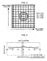
- Fig. 5 is a graph showing field curvature in the first embodiment of the present invention.
- Fig. 6 is a main scanning cross-sectional view of an optical scanner according to a second embodiment of the present invention.
- Fig. 7 is a sub-scanning cross-sectional view of the optical scanner according to the second embodiment of the present invention.
- Fig. 9 is a sub-scanning cross-sectional view of an image forming apparatus according to an embodiment of the present invention.
- Fig. 10 is a diagram of the main part of a color image forming apparatus according to an embodiment of the present invention.
- Fig. 11 is a diagram of the wavefront aberration of a light beam incident on a light deflector in the main scanning direction.
- Figs. 12A, 12B, and 12C are diagrams showing wavefront aberrations caused in the main scanning direction at an off-axis image height by an incident optical system, a focusing optical system, and the overall system, respectively, in a known OFS.
- Figs. 13A, 13B, and 13C are diagrams showing wavefront aberrations caused in the main scanning direction at an off-axis image height by an incident optical system, a focusing optical system, and the overall system, respectively, in a known OFS (including a scanning system composed of a single lens).
- Fig. 14 is a spot diagram at an off-axis image height in the known OFS.
- Figs. 15A and 15B are diagrams illustrating asymmetrical components caused in the phase shape of wavefront aberration by the shapes of symmetrical and asymmetrical optical surfaces, respectively, when a collimated light beam having a wavefront aberration with a symmetrical phase shape on both sides of the chief ray of the light beam passes through the optical surfaces.
- Fig. 16 is a main scanning cross-sectional view of an optical scanner according to a third embodiment of the present invention.
- Fig. 17 is a sub-scanning cross-sectional view of the optical scanner according to the third embodiment of the present invention.
- Fig. 1 is a sectional view of the main part of an optical scanner according to a first embodiment of the present invention in a main scanning direction (a main scanning cross-sectional view).
- Fig. 2 is a sectional view of the main part of the optical scanner in Fig. 1 in a sub-scanning direction (a sub-scanning cross-sectional view).
- the main scanning direction is the direction perpendicular to the rotation axis of a light deflector and the optical axis of scanning optical elements (in the direction in which the light deflector reflects and deflects a light beam (deflection scanning)).
- the sub-scanning direction is the direction parallel to the rotation axis of the light deflector.
- the main scanning cross-section is a plane that is parallel to the main scanning direction and includes the optical axis of a focusing optical system.
- the sub-scanning cross-section is a plane perpendicular to the main scanning cross-section.
- a light source 1 is composed of, for example, a monolithic multibeam semiconductor laser having two light-emitting portions (light-emitting points). Although the light source 1 has the two light-emitting portions in this embodiment, the number of light-emitting portions is not limited to two; the light source 1 can also have a single light-emitting portion or three or more light-emitting portions.
- a cylindrical lens (sub-scanning cylindrical lens) 2 in the form of an anamorphic optical element, has a predetermined power (refractive power) only in the sub-scanning cross-section to convert two divergent light beams emitted from the light source 1 into light beams substantially collimated in the sub-scanning cross-section.
- An aperture (aperture diaphragm) 3 optimally trims the substantially collimated light beams exiting the cylindrical lens 2 into a desired beam shape.
- a collimating lens 4 as a light-collecting optical system, has a predetermined power in the main scanning cross-section to convert the two divergent light beams emitted from the light source 1 into light beams collimated in the main-scanning direction.
- the collimating lens 4 focuses the light beams exiting the cylindrical lens 2, which has a predetermined power only in the sub-scanning direction, onto any deflecting surface 7 of a light deflector 6 described below in the form of a linear image extending in the main scanning direction.
- An incident optical system 5 includes the cylindrical lens 2, which has a predetermined power only in the sub-scanning direction, the aperture 3, the collimating lens 4, and an f ⁇ lens 8a described below.
- the light deflector 6 is composed of, for example, a rotating polygon mirror, and is rotated at a constant rate in a direction indicated by arrow A in the drawings by a driving unit such as a motor (not shown).
- the deflecting surfaces 7 of the light deflector 6 are equivalent to the aperture of the incident optical system 5 in the main scanning direction.
- a focusing optical system 8 has f ⁇ characteristics, including a plastic f ⁇ lens (G1 lens) 8a having a predetermined positive power only in the main scanning cross-section and an elongated plastics material toric lens (G2 lens) 8b having a predetermined power only in the sub-scanning cross-section.
- the focusing optical system 8 focuses the two light beams deflected by the polygon mirror 6, which are based on image information, onto a photosensitive drum surface 10, as a surface to be scanned, in the main scanning cross-section.
- the deflecting surfaces 7 of the polygon mirror 6 are optically conjugated to the photosensitive drum surface 10 in the sub-scanning cross-section to correct surface tilting.
- the deflecting surfaces 7 of the light deflector 6 are equivalent to the aperture of the focusing optical system 8 in the main scanning direction.
- the surfaces of the f ⁇ lens 8a and the toric lens 8b on both sides have a non-arc shape in the main scanning cross-section, as shown in Table 2 below.
- This embodiment employs a double-pass structure in which the light beams passing through the f ⁇ lens 8a (incident light beams) are deflected by the polygon mirror 6 to enter the f ⁇ lens 8a again (scanning light beams).
- the photosensitive drum surface 10 is a surface to be scanned (recording medium surface).
- the two modulated light beams emitted from the multibeam semiconductor laser 1 enter the sub-scanning cylindrical lens 2, which has power only in the sub-scanning direction.
- These light beams are collimated in the sub-scanning cross-section to impinge on any deflecting surface 7 of the polygon mirror 6 through the aperture 3, the collimating lens 4, and the f ⁇ lens 8a.
- the light beams exiting the f ⁇ lens 8a are focused on the deflecting surface 7 in the form of a linear image (elongated in the main scanning direction).
- the light beams impinge on the deflecting surface 7 of the polygon mirror 6 at a predetermined oblique angle in an oblique direction with respect to the deflecting surface 7 (oblique incident optical system).
- the light beams, which are divergent in the main scanning cross-section, are collimated after passing through the aperture 3, the collimating lens 4, and the f ⁇ lens 8a to impinge on the deflecting surface 7 of the polygon mirror 6 in the center of the deflection angle of the polygon mirror 6 (front incidence).
- the light beams incident on the deflecting surface 7, which are collimated in the main scanning cross-section, are adjusted so as to have a sufficiently large width compared to the facet width (reflection width) of the deflecting surface 7 of the polygon mirror 6 in the main scanning direction (OFS).
- the two light beams reflected by the polygon mirror 6 are guided to the photosensitive drum surface 10 through the focusing optical system 8 and the beam-folding mirror 9.
- the two light beams reflected by the polygon mirror 6 scan the photosensitive drum surface 10 in a direction indicated by arrow B in the drawings (the main scanning direction) to write an image on the photosensitive drum surface 10, as a recording medium.
- the focusing optical system 8 has a lower F-number on the incident side in the sub-scanning direction, namely 3.4, than in the main scanning direction, namely 14.
- the sub-scanning cylindrical lens 2 is disposed closer to the light source 1 than the collimating lens 4 to reduce the optical path length.
- the arrangement is not limited to the above arrangement, and the collimating lens 4 can be disposed closer to the light source 1 than the sub-scanning cylindrical lens 2.
- the f ⁇ lens 8a is disposed near the polygon mirror 6 so that the size of the f ⁇ lens 8a can be reduced to achieve lower cost, and, as described above, a double-pass structure is employed, in which both the incident and scanning light beams pass through the f ⁇ lens 8a.
- both surfaces of the f ⁇ lens 8a have a non-arc shape in the main scanning cross-section to provide a compact scanner (to reduce the optical path length from the polygon mirror 6 to the surface to be scanned 10). Accordingly, the scanning angle of the polygon mirror 6 is adjusted to a wide range of field angles, namely ⁇ 20.25°.
- the incident optical system 5 causes a large aberration which readily leads to coma aberration and field curvature.
- the incident optical system 5 and the focusing optical system 8 are constructed such that both aberrations (wavefront aberrations) occurring in the two optical systems when the light beams impinge on the surface to be scanned 10 at an off-axis image height are asymmetrical on both sides of the center of the light beams and the directions of the aberrations are opposite to each other.
- Such a structure significantly inhibits coma aberration and field curvature.
- the incident optical system 5 and the focusing optical system 8 are constructed such that the directions of the aberrations (wavefront aberrations) are opposite to each other at every image height in the overall effective scanning region (the overall image-forming region), although the directions of the aberrations do not necessarily have to be opposite to each other at every image height; they may also be opposite only at certain image heights.
- the directions of the aberrations do not necessarily have to be opposite to each other at every off-axis image height; they may also be opposite only at limited off-axis image heights.
- the most serious problem for optical scanners is coma aberration and field curvature due to wavefront aberration at the maximum image height.
- Fig. 3A shows that the incident optical system 5 causes a wavefront aberration that is asymmetrical in the main scanning direction.
- the phase of the wavefront aberration on the plus image height side leads that on the minus height image side.
- the phase difference is canceled out by causing a wavefront aberration in the focusing optical system 8 in the direction opposite the direction of the wavefront aberration occurring in the incident optical system 5, as shown in Fig. 3B . That is, the focusing optical system 8 is constructed so that the phase of the wavefront aberration on the minus image height side can catch up with that on the plus image height side in the focusing optical system 8. Referring to Fig. 3C , such correction leads to an acceptable wavefront aberration with no coma aberration in the overall system.
- the curvature of the wavefront aberration occurring in the overall system is sufficiently inhibited by canceling out the curvature of the wavefront aberration in the incident optical system 5.
- the overall system can therefore sufficiently reduce the deviation of focal position due to the curvature of the wavefront aberration at all image heights to suppress differences in focal position at different image heights on the surface to be scanned 10 to an acceptable level. That is, this system can suppress field curvature due to the curvature of the wavefront aberration on the surface to be scanned 10 to an acceptable level.
- Fig. 5 is a graph showing field curvature characteristics in the main scanning cross-section and the sub-scanning cross-section in this embodiment.
- Fig. 5 shows that the field curvature is excellently corrected in the main scanning cross-section and the sub-scanning cross-section. According to this embodiment, therefore, the field curvature is corrected, and thus the expansion of beam spots is suppressed to an acceptable level.
- all lens surfaces of the f ⁇ lens 8a and the elongated toric lens 8b have a non-arc shape in the main scanning cross-section to cause the aberration required for suppressing coma aberration and field curvature to such a level that they have no effect on spots.
- the f ⁇ lens 8a and the toric lens 8b are made of a plastics material.
- the width of a light beam incident at the maximum image height on the non-arc-shaped lens surfaces (in the main scanning cross-section) of the f ⁇ lens 8a and the toric lens 8b in the focusing optical system 8 must be larger in the main scanning direction than the width of the light beam on a surface that causes aberration in the incident optical system 5. Otherwise, the lens surfaces of the f ⁇ lens 8a and the toric lens 8b must be formed into a complicated shape in order to correct the asymmetry of the aberration of the light beam in the main scanning direction. As a result, the non-arc-shaped lens surfaces (in the main scanning cross-section) of the f ⁇ lens 8a and the toric lens 8b tend to become more difficult to form.
- the width W1 of the light beam passing through the non-arc-shaped lens surfaces (in the main scanning cross-section) of the f ⁇ lens 8a and the toric lens 8b in the main scanning direction at the maximum image height is adjusted to at least 1.8 times the width W2 of the light beam passing through the arc-shaped lens surface (in the main scanning cross-section) in the incident optical system 5, namely W1/W2 ⁇ 1.8. Accordingly, the aberration can be excellently corrected with no increased difficulty in forming the non-arc lens surfaces (in the main scanning cross-section) of the f ⁇ lens 8a and the toric lens 8b.
- the width of the light beam on a second surface (light-exiting surface) of the collimating lens 4 in the main scanning direction namely W2
- the width W2 corresponds to the region through which the light beam incident at the maximum image height passes; the region differs for each image height in an OFS.
- the width of the light beam on a first surface (light-entering surface) of the f ⁇ lens 8a in the main scanning direction, namely W1-1, is 2.80 mm.
- the width of the light beam on a second surface (light-exiting surface) of the f ⁇ lens 8a in the main scanning direction, namely W1-2, is 2.53 mm.
- the width of the light beam on a first surface (light-entering surface) of the toric lens 8b in the main scanning direction, namely W1-3, is 2.93 mm.
- the width of the light beam on a second surface (light-exiting surface) of the toric lens 8b in the main scanning direction, namely W1-4, is 2.75 mm.
- the width W1 is defined as the highest value among W1-1, W1-2, W1-3, and W1-4, namely 2.93 mm (W1-3).
- the second surface (light-exiting surface) of the collimating lens 4 has an arc shape in the main scanning cross-section in the incident optical system 5.
- W1/W2 the ratio of W1/W2 to 1.8 or more, where W2 is defined as the highest value among the widths of the light beam on the individual lens surfaces.
- the largest coma aberration in the incident optical system 5 occurs at the maximum image height; therefore, the aberration can be excellently corrected not only at the maximum image height but also at intermediate image heights by adjusting the ratio of W1/W2 to 1.8 or more at the maximum image height.
- the optical surface in Fig. 15A has a symmetrical shape on both sides of the chief ray of the light beam in any cross-section.
- ⁇ U indicates the gradient of the optical surface at the position through which an upper ray (a marginal ray adjacent to an end of the optical surface) of the light beam passes with respect to the position through which the chief ray passes
- ⁇ L indicates the gradient of the optical surface at the position through which a lower ray (a marginal ray adjacent to the optical axis of the optical surface) of the light beam passes with respect to the position through which the chief ray passes.
- the upper and lower rays of the light beam are subjected to refractive powers that are symmetrical on both sides of the optical axis. Accordingly, the light beam exiting the optical surface is a collimated light beam having a wavefront aberration that remains symmetrical on both sides of the chief ray of the light beam, and the intersection point of the upper ray and the chief ray substantially agrees with that of the lower ray and the chief ray.
- the optical surface in Fig. 15B has an asymmetrical shape on both sides of the chief ray of the light beam in any cross-section.
- ⁇ U indicates the gradient of the optical surface at the position through which the upper ray (a marginal ray adjacent to an end of the optical surface) of the light beam passes with respect to the position through which the chief ray passes
- ⁇ L indicates the gradient of the optical surface at the position through which the lower ray (a marginal ray adjacent to the optical axis of the optical surface) of the light beam passes with respect to the position through which the chief ray passes.
- the light beam exiting the optical surface is a convergent light beam having a wavefront aberration with an asymmetrical phase shape on both sides of the chief ray of the light beam, and the intersection point of the upper ray and the chief ray deviates from that of the lower ray and the chief ray. That is, a larger difference ⁇ between the gradients of the lens surface at the positions through which the upper and lower rays pass with respect to the position through which the chief ray passes results in a larger asymmetrical component (with the chief ray as the central axis) caused in the phase shape of the wavefront aberration when the light beam passes through the optical surface.
- the asymmetrical component caused in the phase shape of the wavefront aberration by the overall optical system with the chief ray as the central axis is the sum of the asymmetrical components caused in the phase shape of the wavefront aberration by the individual optical surfaces with the chief ray as the central axis.
- H ⁇ ⁇ i Ui ⁇ ( ni - 1 ) ⁇ ⁇
- Ui a coefficient that is -1 for a light-entering transparent optical surface and that is +1 for a light-exiting transparent optical surface or a reflective optical surface
- ni a coefficient that equals the refractive index of glass for a transparent optical surface and that is 2 for a reflective optical surface.
- the equation (6) is applied to the case of a light beam incident at any image height in the main-scanning cross-section in an optical system (a focusing optical system or an incident optical system) in an optical scanner.
- the gradient dX/dY of the i-th optical surface at the position through which a marginal ray, adjacent to an end of the optical surface, of a light beam incident at the maximum image height passes with respect to the optical axis of the optical surface in the main-scanning cross-section is indicated by ai.
- the gradient dX/dY of the i-th optical surface at the position through which the chief ray of the light beam incident at the maximum image height passes with respect to the optical axis of the optical surface in the main-scanning cross-section is indicated by bi.
- the gradient dX/dY of the i-th optical surface at the position through which a marginal ray, adjacent to the optical axis of the optical surface, of the light beam incident at the maximum image height passes with respect to the optical axis of the optical surface in the main-scanning cross-section is indicated by ci.
- the equation (8) represents the correlation between the surface shapes and the asymmetrical component H' caused in the phase shape of the wavefront aberration by the optical system (a focusing optical system or an incident optical system) in the optical scanner when the light beam incident at any image height passes through the overall optical system in the optical scanner with the chief ray of the light beam as the central axis in the main-scanning cross-section. If an optical system in an optical scanner used in an image forming apparatus produces a large asymmetrical component H', a light beam is focused on a surface to be scanned in a spot with an asymmetrical shape, and thus the optical scanner disadvantageously cannot provide an excellent image.
- the individual values are adjusted so that the following equations can be satisfied to reduce the asymmetrical component H' of the phase shape of the wavefront aberration and thus achieve focused spots with an excellent shape.
- the incident optical system 5 has m optical surfaces (m ⁇ 1)
- the focusing optical system 8 has p optical surfaces (P ⁇ 1)
- the optical surfaces in the incident optical system 5 are the first to m-th surfaces from the light source side
- the optical surfaces in the focusing optical system 8 are the (m+1)-th to (p+m+1)-th surfaces from the light deflector side
- the following equations are satisfied: B / A ⁇ 0 f ⁇
- A is the sum of the asymmetrical components caused in the phase shape of the wavefront aberration in the main-scanning cross-section when
- A is the sum of the asymmetrical components caused in the phase shape of the wavefront aberration when the light beam incident at the maximum image height passes through the incident optical system 5 with the chief ray of the light beam as the central axis in the main-scanning cross-section.
- B is the sum of the asymmetrical components caused in the phase shape of the wavefront aberration when the light beam incident at the maximum image height passes through the focusing optical system 8 with the chief ray of the light beam as the central axis in the main-scanning cross-section.
- the shapes of the lens surfaces are adjusted so that the directions of the asymmetrical components caused in the phase shapes of the wavefront aberrations by the incident optical system 5 and the focusing optical system 8 with the chief ray of the light beam as the central axis are opposite to each other, as shown in the equation (9).
- This reduces the asymmetrical component H' ( A+B) caused in the phase shape of the wavefront aberration by the overall optical system in the optical scanner with the chief ray of the light beam as the central axis.
- the left side of the equation (10) is an approximation of the amount of deviation ⁇ Y in the main-scanning cross-section between the intersection point of the chief ray and lower ray of the light beam incident on the surface to be scanned 10 at the maximum image height and the intersection point of the chief ray and upper ray of the light beam.
- This approximation is based on the focal length of the focusing optical system 8 and the asymmetrical component caused in the phase shape of the wavefront aberration by the overall optical system in the optical scanner with the chief ray of the light beam as the central axis.
- the equation (10) means that the amount of deviation ⁇ Y is not larger than twice the diameter of a focused spot in the main scanning direction. If the equation (10) is satisfied, the asymmetry of the shape of a focused spot on the surface to be scanned 10 can be sufficiently reduced to provide an excellent image.
- the following equation (10') should be satisfied: f ⁇
- the amount of deviation ⁇ Y in the main-scanning cross-section between the intersection point of the chief ray and lower ray of the light beam incident on the surface to be scanned 10 at the maximum image height and the intersection point of the chief ray and upper ray of the light beam is not larger than the diameter of a focused spot on the surface to be scanned 10 in the main scanning direction.
- spots with an excellent shape can be achieved to provide a higher-quality image.
- the largest coma aberration in the main-scanning cross-section in the incident optical system 5 and the focusing optical system 8 tends to occur at the maximum image height. If, therefore, the above equations (9) to (12) are satisfied at the maximum image height, the coma aberration can be sufficiently reduced at all image heights to provide spots with an excellent shape.
- ai, bi, and ci are first order differentials dX/dY according to equation (1) set out below, which indicates the shape of a generating line.
- A is a negative value, namely -1.8E-4
- the focusing optical system 8 is constructed so that coma aberration and field curvature due to the aberration occurring in the incident optical system 5 can be canceled out.
- the incident optical system 5 therefore does not require an aspherical lens or a plurality of lenses for correcting spherical aberration.
- the incident optical system 5 can be composed of only the two lenses, namely the collimating lens 4 (having a flat light-entering surface and a convex spherical light-exiting surface) and the cylindrical lens 2 (having a flat light-entering surface and a convex light-exiting surface with power in the sub-scanning direction).
- the incident optical system 5 is therefore advantageous in terms of ease of manufacture.
- the optical scanner is advantageous in terms of increasing speed because the F-number on the incident side in the main scanning direction can be reduced to enhance luminous efficiency (in this embodiment, as described above, the F-number on the incident side in the main scanning direction is 14, and the F-number on the incident side in the sub-scanning direction is 3.4)
- Table 1 shows the properties of the focusing optical system 8 in this embodiment.
- Table 2 shows data (R, D, and N) of the focusing optical system 8 in this embodiment.
- Table 3 shows aspherical shapes in this embodiment.
- Laser power E 5 (mW) Number of light-emitting points N 2 Interval between light-emitting points d 1 90 ( ⁇ m) Wavelength used ⁇ 790 (nm) Incident F-number in main scanning direction Fm 14 - Incident F-number in sub-scanning direction Fs 3.4 - Width of deflecting surface 7 in main scanning direction W 2.85 (mm) Effective light beam width in main scanning direction Wo 5.06 (mm) Diameter of circle circumscribing polygon mirror 6 ⁇ 1 7.45 (mm) Diameter of circle inscribed in polygon mirror 6 ⁇ 2 6.88 (mm) Oblique incident angle in sub-scanning cross-section ⁇ 3 (deg) Number of deflecting surfaces 7 M 8 (surfaces) Scanning efficiency Du 90 (%) Maximum scanning angle
- the aspherical surfaces are defined by the following equations.
- the intersection point of a curved surface of a lens and the optical axis thereof is defined as an origin point.
- the optical axis direction is defined as the x-axis.
- the axis orthogonal to the optical axis in the main scanning cross-section is defined as the y-axis.
- the axis orthogonal to the optical axis in the sub-scanning cross-section is defined as the z-axis.
- a generating line is defined as the cutting line of the xy-plane and the curved surface, and a line perpendicular to the generating line is defined as the cutting line of the xz-plane and the curved surface.
- r 0 is the radius of curvature of the line perpendicular to the generating line on the optical axis; and D 2 , D 4 , D 6 , D 8 , and D 10 are coefficients.
- Fig. 6 is a sectional view of the main part of an optical scanner according to a second embodiment of the present invention in a main scanning direction (a main scanning cross-sectional view).
- Fig. 2 is a sectional view of the main part of the optical scanner in Fig. 6 in a sub-scanning direction (a sub-scanning cross-sectional view).
- Figs. 6 and 7 the same reference numerals as in Figs. 1 and 2 indicate the same components.
- the second embodiment is different from the first embodiment in that the collimating lens 4 is disposed closer to the light source 1 than the sub-scanning cylindrical lens 2 in the incident optical system 5, that the incident optical system 5 further includes a correcting lens 64, and that the focusing optical system 8 is composed of a single toric lens 8.
- the light-entering surface of the toric lens 8 is flat, and the light-exiting surface thereof has a non-arc shape with positive power.
- the light-entering surface of the toric lens 8 has an arc shape with negative power, and the light-exiting surface thereof has an arc shape with positive power.
- Another difference is the use of a single-pass structure in which only the light beam reflected by any deflecting surface 7 of the polygon mirror 6 passes through the toric lens 8, that is, in which the light beam incident on the deflecting surface 7 of the polygon mirror 6 does not pass through the toric lens 8.
- the other structures and optical operations are substantially the same as those in the first embodiment, and thus the same effect can be achieved.
- this optical scanner can correct field curvature in the main scanning direction, provide excellent f ⁇ characteristics, and correct field curvature in the sub-scanning direction and surface tilting (the deflecting surfaces 7 are conjugated to the photosensitive drum surface 10).
- the light-exiting surface of the correcting lens 64 in Fig. 6 has a non-arc shape in the main scanning cross-section and is flat in the sub-scanning cross-section so that a wavefront aberration occurs in a direction opposite the direction of coma aberration occurring in the focusing optical system 8 at all image heights.
- the focusing optical system 8 has difficulty in completely inhibiting the coma aberration occurring in the focusing optical system 8 itself at all image heights because the focusing optical system 8 is composed of a single toric lens.
- the correcting lens 64 is provided in the incident optical system 5 so that a wavefront aberration occurs in the incident optical system 5 in a direction opposite the direction of the wavefront aberration occurring in the focusing optical system 8 to suppress coma aberration and field curvature.
- a wavefront aberration occurs in the incident optical system 5 in a direction opposite the direction of the wavefront aberration occurring in the focusing optical system 8.
- these wavefront aberrations cancel each other out so that the wavefront aberration in the overall system is excellently corrected.
- the correcting lens 64 which has an aspherical surface, is provided in the incident optical system 5 so that an aberration occurs in the incident optical system 5 to cancel out the coma aberration occurring in the focusing optical system 8 at all image heights, thus providing excellent spots.
- the curvature of the wavefront aberration in the focusing optical system 8 is canceled out by the wavefront aberration in the opposite direction, and thus the curvature of the wavefront aberration in the overall system is sufficiently inhibited.
- the overall system can therefore sufficiently reduce the deviation of focal position due to the curvature of the wavefront aberration at all image heights to suppress field curvature due to the curvature of the wavefront aberration on the surface to be scanned 10 to an acceptable level.
- the non-arc-shaped lens surface (in the main scanning cross-section) must be formed into a complicated shape in order to correct the coma aberration. As a result, the non-arc-shaped lens surface (in the main scanning cross-section) tends to become more difficult to form.
- the width of a region through which the light beam passes on a second surface (light-exiting surface) of the correcting lens 64, namely W3, is 2.63 mm.
- the width of the region through which the light beam passes on the second surface (light-exiting surface) of the toric lens 8 in the focusing optical system 8, namely W4, is 1.30 mm.
- the second surface (light-exiting surface) of the correcting lens 64 has a non-arc shape in the main scanning cross-section.
- the same effect as above can be achieved by adjusting the ratio of W3/W4 to 1.8 or more, where W3 is defined as the highest value among the widths of the regions through which the light beam pass on the individual lens surfaces. Accordingly, the aberration can be excellently corrected, and thus excellent spots can be achieved.
- the second surface (light-exiting surface) of the toric lens 8 causes coma aberration in the focusing optical system 8.
- W3/W4 the ratio of W3/W4 to 1.8 or more, where W4 is defined as the highest value among the widths of the regions through which the light beam pass on the individual lens surfaces. Accordingly, the coma aberration can be excellently corrected, and thus excellent spots can be achieved.
- the largest coma aberration in the focusing optical system 8 tends to occur at the maximum image height; therefore, the aberration can be excellently corrected not only at the maximum image height but also at intermediate image heights by adjusting the ratio of W3/W4 to 1.8 or more at the maximum image height.
- the correcting lens 64 is composed of an aspherical lens having a non-arc shape in the main scanning cross-section in this embodiment, the structure thereof is not limited to that arrangement; for example, the correcting lens 64 can also be composed of a plurality of aspherical lenses.
- a single-pass structure is used in this embodiment, the structure used is not limited to a single-pass structure; for example, a double-pass structure can be used.
- the focusing optical system 8 is composed of a single toric lens in this embodiment, the structure thereof is not limited to that arrangement; for example, the focusing optical system 8 can be composed of a plurality of lenses. In this case, a sufficient effect can be achieved if an aberration occurs in the focusing optical system 8.
- the incidence angle is not limited to a right angle; it can instead be an oblique angle.
- the focusing optical system 8 includes a toric lens having a non-arc shape in the main scanning cross-section, and the correcting lens 64, which has a non-arc shape in the main scanning cross-section, can be provided in the incident optical system 5.
- Fig. 16 is a sectional view of the main part of an optical scanner according to a third embodiment of the present invention in a main scanning direction (a main scanning cross-sectional view).
- Fig. 17 is a sectional view of the main part of the optical scanner in Fig. 16 in a sub-scanning direction (a sub-scanning cross-sectional view).
- a beam-folding mirror 15 for allowing a light beam to impinge on the polygon mirror 6 in Fig. 16 is not shown.
- the same reference numerals as in Figs. 1 and 2 indicate the same components.
- the third embodiment is different from the first embodiment in that the F-number on the incident side in the main scanning direction in the incident optical system 5 is lower than that in the first embodiment, namely 7, that the focusing optical system 8 is composed of a single toric lens 8, and that the light beam reflected and deflected by the polygon mirror 6 is adjusted to a weakly convergent light beam to reduce the thickness of the toric lens 8 in the main-scanning cross-section.
- both the light-entering surface and the light-exiting surface of the toric lens 8 have a non-arc shape.
- the light-entering surface of the toric lens 8 has an arc shape with negative power, and the light-exiting surface thereof has an arc shape with positive power.
- Another difference is the use of a single-pass structure in which only the light beam reflected by any deflecting surface 7 of the polygon mirror 6 passes through the toric lens 8, that is, in which the light beam incident on the deflecting surface 7 of the polygon mirror 6 does not pass through the toric lens 8.
- the other structures and optical operations are substantially the same as those in the first embodiment, and thus the same effect can be achieved.
- Table 5 shows the properties of the focusing optical system 8 in this embodiment.
- Table 6 shows data (R, D, and N) of the focusing optical system 8 in this embodiment.
- Table 7 shows aspherical shapes in this embodiment.
- A 2.3E-4
- B -3.6E-4
- B/A -1.55 ⁇ 0, meaning that the equation (9) is satisfied.
- A is a positive value and B is a negative value in this embodiment while A is a negative value and B is a positive value in the first embodiment.
- Fig. 9 is a sectional view of the main part of an image forming apparatus according to an embodiment of the present invention in the sub-scanning direction.
- an external device 117 such as a personal computer, inputs code data Dc to an image forming apparatus 104.
- a printer controller 111 in the apparatus 104 converts the code data Dc into image data (dot data) Di which is then input to an optical scanner 100 having the structure shown in the first or second embodiment.
- the optical scanner 100 emits a light beam 103 modulated according to the image data Di to scan the photosensitive surface of a photosensitive drum 101, as a member for bearing an electrostatic latent image (photosensitive member), in the main scanning direction.
- a motor 115 rotates the photosensitive drum 101 clockwise to move the photosensitive surface thereof in the sub-scanning direction, which is a direction orthogonal to the main scanning direction, with respect to the light beam 103.
- a charging roller 102 is brought into contact with the photosensitive surface of the photosensitive drum 101 on the upper side thereof to uniformly charge the photosensitive surface. The photosensitive surface charged by the charging roller 102 is scanned by the light beam 103 emitted from the optical scanner 100.
- the light beam 103 which is modulated according to the image data Di, as described above, scans the photosensitive surface to form an electrostatic latent image on it.
- the electrostatic latent image is developed into a toner image by a developing unit 107 brought into contact with the photosensitive drum 101 downstream of the scanning position of the light beam 103 in the rotational direction of the photosensitive drum 101.
- the toner image developed by the developing unit 107 is transferred to a sheet of paper 112, as a transfer material, by a transfer roller 108 provided on the lower side of the photosensitive drum 101 such that they are opposed to each other.
- Sheets of paper 112 are stored in a sheet cassette 109 provided in front of the photosensitive drum 101 (on the right side in Fig. 9 ), though they may also be manually fed.
- a feeding roller 110 is provided at an end of the sheet cassette 109 to feed the sheets of paper 112 into a carrier line.
- the sheet of paper 112 having the unfused toner image is then carried to a fusing unit disposed on the backside of the photosensitive drum 101 (on the left side in Fig. 9 ).
- the fusing unit includes a fusing roller 113 having an internal fusing heater (not shown) and a pressure roller 114.
- the fusing roller 113 and the pressure roller 114 form a nip.
- the sheet of paper 112 carried from the transfer roller 108 is pressed and heated at the nip between the fusing roller 113 and the pressure roller 114 to fuse the unfused toner image on the sheet of paper 112.
- the sheet of paper 112 having the fused image is ejected from the image forming apparatus 104 by an ejecting roller 116 to the rear of the fusing roller 113.
- the printer controller 111 not only converts data, as described above, but also controls the individual units in the image forming apparatus 104, such as the motor 115 and a motor for the polygon mirror in the optical scanner 100, though the control function is not shown in Fig. 9 .
- the recording density of the image forming apparatus used in the present invention is not particularly limited.
- the first and second embodiments of the present invention have a more significant effect for image forming apparatuses with recording densities of 1,200 dpi or more bearing in mind that higher image quality is required with increasing recording densities.
- Fig. 10 is a sectional view of the main part of a color image forming apparatus according to an embodiment of the present invention.
- This color image forming apparatus is a tandem-type apparatus in which four optical scanners are arranged in tandem to record image information on the surfaces of photosensitive drums, as image-bearing members.
- a color image forming apparatus 60 includes optical scanners 11, 12, 13, and 14 having the structure shown in the first or second embodiment, photosensitive drums 21, 22, 23, and 24, as image-bearing members, developing units 31, 32, 33, and 34, and a carrier belt 51.
- an external device 52 such as a personal computer, input color signals corresponding to R (red), G (green), and B (blue) to the color image forming apparatus 60.
- a printer controller 53 in the apparatus 60 converts the color signals into image data (dot data) corresponding to C (cyan), M (magenta), Y (yellow), and B (black).
- the image data is then input to the optical scanners 11, 12, 13, and 14, which emit light beams 41, 42, 43, and 44 modulated according to the image data to scan photosensitive surfaces of the photosensitive drums 21, 22, 23, and 24, respectively, in the main scanning direction.
- the optical scanners 11, 12, 13, and 14 are arranged in tandem and correspond to C (cyan), M (magenta), Y (yellow), and B (black), respectively.
- the optical scanners 11, 12, 13, and 14 record image signals (image information) on the surfaces of the photosensitive drums 21, 22, 23, and 24, respectively, to print a color image at high speed.
- the optical scanners 11, 12, 13, and 14 emit the light beams 41, 42, 43, and 44, respectively, according to the image data to form latent images of the individual colors on the corresponding photosensitive drums 21, 22, 23, and 24.
- the images are superimposed on a recording material to form a full-color image.
- the external device 52 used can be, for example, a color image reader having a CCD sensor; in this case, the color image reader and the color image forming apparatus 60 constitute a color digital copier.
Applications Claiming Priority (2)
| Application Number | Priority Date | Filing Date | Title |
|---|---|---|---|
| JP2004270051 | 2004-09-16 | ||
| EP05255750A EP1637916B1 (fr) | 2004-09-16 | 2005-09-16 | Système de balayage optique avec correction des aberrations et appareil de formation d'image utilisant ce dernier |
Related Parent Applications (2)
| Application Number | Title | Priority Date | Filing Date |
|---|---|---|---|
| EP05255750A Division EP1637916B1 (fr) | 2004-09-16 | 2005-09-16 | Système de balayage optique avec correction des aberrations et appareil de formation d'image utilisant ce dernier |
| EP05255750.1 Division | 2005-09-16 |
Publications (3)
| Publication Number | Publication Date |
|---|---|
| EP2003483A2 true EP2003483A2 (fr) | 2008-12-17 |
| EP2003483A3 EP2003483A3 (fr) | 2012-03-07 |
| EP2003483B1 EP2003483B1 (fr) | 2013-11-20 |
Family
ID=35502575
Family Applications (2)
| Application Number | Title | Priority Date | Filing Date |
|---|---|---|---|
| EP05255750A Expired - Fee Related EP1637916B1 (fr) | 2004-09-16 | 2005-09-16 | Système de balayage optique avec correction des aberrations et appareil de formation d'image utilisant ce dernier |
| EP08165869.2A Expired - Fee Related EP2003483B1 (fr) | 2004-09-16 | 2005-09-16 | Méthode de formation d'un système de balayage optique avec correction des aberrations |
Family Applications Before (1)
| Application Number | Title | Priority Date | Filing Date |
|---|---|---|---|
| EP05255750A Expired - Fee Related EP1637916B1 (fr) | 2004-09-16 | 2005-09-16 | Système de balayage optique avec correction des aberrations et appareil de formation d'image utilisant ce dernier |
Country Status (5)
| Country | Link |
|---|---|
| US (1) | US7085031B2 (fr) |
| EP (2) | EP1637916B1 (fr) |
| KR (1) | KR100702169B1 (fr) |
| CN (1) | CN100357788C (fr) |
| DE (1) | DE602005020397D1 (fr) |
Families Citing this family (13)
| Publication number | Priority date | Publication date | Assignee | Title |
|---|---|---|---|---|
| US7286844B1 (en) * | 2003-01-31 | 2007-10-23 | Bbn Technologies Corp. | Systems and methods for three dimensional antenna selection and power control in an Ad-Hoc wireless network |
| EP1701198A1 (fr) * | 2005-03-09 | 2006-09-13 | Canon Kabushiki Kaisha | Dispositif de balayage optique et appareil de formation d'images |
| US20060209171A1 (en) * | 2005-03-15 | 2006-09-21 | Kabushiki Kaisha Toshiba | Optical beam scanning device and image forming apparatus |
| JP5164345B2 (ja) * | 2005-08-22 | 2013-03-21 | キヤノン株式会社 | 光走査装置及びそれを用いた画像形成装置 |
| US7924728B2 (en) * | 2006-08-25 | 2011-04-12 | Raytheon Bbn Technologies Corp | Systems and methods for energy-conscious communication in wireless ad-hoc networks |
| US7969634B2 (en) * | 2007-02-28 | 2011-06-28 | Ricoh Company, Limited | Optical scanning device and image forming apparatus |
| JP5476659B2 (ja) * | 2007-09-14 | 2014-04-23 | 株式会社リコー | マルチビーム光走査装置および画像形成装置 |
| JP5177182B2 (ja) | 2010-06-30 | 2013-04-03 | コニカミノルタビジネステクノロジーズ株式会社 | 光走査装置 |
| EP2400337B1 (fr) * | 2010-06-22 | 2019-12-11 | Konica Minolta Business Technologies, Inc. | Dispositif de balayage optique |
| JP5943610B2 (ja) * | 2012-01-10 | 2016-07-05 | キヤノン株式会社 | 光走査装置及びそれを備える画像形成装置 |
| JP6045455B2 (ja) * | 2013-08-02 | 2016-12-14 | キヤノン株式会社 | 光走査装置及びそれを用いた画像形成装置 |
| CN112612192B (zh) * | 2020-12-18 | 2022-11-22 | 珠海奔图电子有限公司 | 一种光学扫描单元及图像形成装置 |
| CN113009797A (zh) * | 2021-05-24 | 2021-06-22 | 珠海奔图电子有限公司 | 光学扫描装置及电子成像设备 |
Citations (5)
| Publication number | Priority date | Publication date | Assignee | Title |
|---|---|---|---|---|
| EP0366039A2 (fr) | 1988-10-25 | 1990-05-02 | Dainippon Screen Mfg. Co., Ltd. | Système optique de balayage |
| EP0378149A2 (fr) | 1989-01-09 | 1990-07-18 | Canon Kabushiki Kaisha | Système optique de balayage achromatique |
| JPH09304720A (ja) | 1996-05-10 | 1997-11-28 | Fuji Xerox Co Ltd | 光学走査装置及び光学レンズ |
| US6104521A (en) | 1994-07-07 | 2000-08-15 | Asahi Kogaku Kogyo Kabushiki Kaisha | Scanning optical systems |
| JP2001059946A (ja) | 1999-08-23 | 2001-03-06 | Canon Inc | 光走査光学装置及びそれを用いた画像形成装置 |
Family Cites Families (1)
| Publication number | Priority date | Publication date | Assignee | Title |
|---|---|---|---|---|
| US3784277A (en) * | 1969-12-15 | 1974-01-08 | Polaroid Corp | Corrected optical system for shallow camera or the like, components thereof |
-
2005
- 2005-09-07 US US11/221,478 patent/US7085031B2/en not_active Expired - Fee Related
- 2005-09-16 EP EP05255750A patent/EP1637916B1/fr not_active Expired - Fee Related
- 2005-09-16 CN CNB200510103964XA patent/CN100357788C/zh not_active Expired - Fee Related
- 2005-09-16 DE DE602005020397T patent/DE602005020397D1/de active Active
- 2005-09-16 KR KR1020050086598A patent/KR100702169B1/ko not_active IP Right Cessation
- 2005-09-16 EP EP08165869.2A patent/EP2003483B1/fr not_active Expired - Fee Related
Patent Citations (6)
| Publication number | Priority date | Publication date | Assignee | Title |
|---|---|---|---|---|
| EP0366039A2 (fr) | 1988-10-25 | 1990-05-02 | Dainippon Screen Mfg. Co., Ltd. | Système optique de balayage |
| EP0378149A2 (fr) | 1989-01-09 | 1990-07-18 | Canon Kabushiki Kaisha | Système optique de balayage achromatique |
| US6104521A (en) | 1994-07-07 | 2000-08-15 | Asahi Kogaku Kogyo Kabushiki Kaisha | Scanning optical systems |
| JPH09304720A (ja) | 1996-05-10 | 1997-11-28 | Fuji Xerox Co Ltd | 光学走査装置及び光学レンズ |
| US5757535A (en) | 1996-05-10 | 1998-05-26 | Fuji Xerox Co., Ltd. | Optical scanner |
| JP2001059946A (ja) | 1999-08-23 | 2001-03-06 | Canon Inc | 光走査光学装置及びそれを用いた画像形成装置 |
Also Published As
| Publication number | Publication date |
|---|---|
| KR100702169B1 (ko) | 2007-03-30 |
| EP1637916B1 (fr) | 2010-04-07 |
| EP1637916A1 (fr) | 2006-03-22 |
| DE602005020397D1 (de) | 2010-05-20 |
| KR20060051366A (ko) | 2006-05-19 |
| EP2003483B1 (fr) | 2013-11-20 |
| CN1749805A (zh) | 2006-03-22 |
| CN100357788C (zh) | 2007-12-26 |
| EP2003483A3 (fr) | 2012-03-07 |
| US20060054799A1 (en) | 2006-03-16 |
| US7085031B2 (en) | 2006-08-01 |
Similar Documents
| Publication | Publication Date | Title |
|---|---|---|
| EP1637916B1 (fr) | Système de balayage optique avec correction des aberrations et appareil de formation d'image utilisant ce dernier | |
| US7380720B2 (en) | Optical scanning system and image forming apparatus using the same | |
| US8077193B2 (en) | Optical scanning device and image forming apparatus using the same | |
| US7550712B2 (en) | Optical scanning system with reduced spherical aberration and image forming apparatus using the same | |
| US8217980B2 (en) | Multi-beam optical scanning device and image forming apparatus using the same | |
| EP2051126A2 (fr) | Dispositif de balayage optique et appareil de formation d'images l'utilisant | |
| US7598974B2 (en) | Multi-beam optical scanning device | |
| KR101078513B1 (ko) | 광주사 장치 및 그것을 사용한 화상 형성 장치 | |
| US8400699B2 (en) | Optical scanning device and image forming apparatus using the same | |
| EP1832911B1 (fr) | Dispositif de balayage optique et appareil de formation d'images | |
| EP1939666B1 (fr) | Dispositif de balayage optique et appareil de formation d'images l'utilisant | |
| EP1795942B1 (fr) | Dispositif de balayage optique et appareil de formation d'images l'utilisant | |
| US7791632B2 (en) | Optical scanning device and image forming apparatus using the same | |
| EP1726982B1 (fr) | Appareil de lecture optique et appareil de formation d'images | |
| US7149019B2 (en) | Optical scanning system and image forming apparatus using the same | |
| EP1336889B1 (fr) | Dispositif de balayage optique et appareil de formation d'images utilisant ledit dispositif | |
| EP1701198A1 (fr) | Dispositif de balayage optique et appareil de formation d'images | |
| US8531738B2 (en) | Optical scanning apparatus and image forming apparatus using the same | |
| JP2004317790A (ja) | 光走査装置 | |
| JP2006113552A (ja) | 光走査装置及びそれを用いた画像形成装置 | |
| JP2004198894A (ja) | 走査光学装置及びそれを用いた画像形成装置 |
Legal Events
| Date | Code | Title | Description |
|---|---|---|---|
| PUAI | Public reference made under article 153(3) epc to a published international application that has entered the european phase |
Free format text: ORIGINAL CODE: 0009012 |
|
| AC | Divisional application: reference to earlier application |
Ref document number: 1637916 Country of ref document: EP Kind code of ref document: P |
|
| AK | Designated contracting states |
Kind code of ref document: A2 Designated state(s): DE FR GB |
|
| PUAL | Search report despatched |
Free format text: ORIGINAL CODE: 0009013 |
|
| AK | Designated contracting states |
Kind code of ref document: A3 Designated state(s): DE FR GB |
|
| RIC1 | Information provided on ipc code assigned before grant |
Ipc: G02B 27/00 20060101ALI20120131BHEP Ipc: G02B 26/12 20060101AFI20120131BHEP |
|
| 17P | Request for examination filed |
Effective date: 20120907 |
|
| AKX | Designation fees paid |
Designated state(s): DE FR GB |
|
| GRAP | Despatch of communication of intention to grant a patent |
Free format text: ORIGINAL CODE: EPIDOSNIGR1 |
|
| INTG | Intention to grant announced |
Effective date: 20130626 |
|
| GRAS | Grant fee paid |
Free format text: ORIGINAL CODE: EPIDOSNIGR3 |
|
| GRAA | (expected) grant |
Free format text: ORIGINAL CODE: 0009210 |
|
| AC | Divisional application: reference to earlier application |
Ref document number: 1637916 Country of ref document: EP Kind code of ref document: P |
|
| AK | Designated contracting states |
Kind code of ref document: B1 Designated state(s): DE FR GB |
|
| REG | Reference to a national code |
Ref country code: GB Ref legal event code: FG4D |
|
| REG | Reference to a national code |
Ref country code: DE Ref legal event code: R096 Ref document number: 602005041966 Country of ref document: DE Effective date: 20140116 |
|
| REG | Reference to a national code |
Ref country code: DE Ref legal event code: R097 Ref document number: 602005041966 Country of ref document: DE |
|
| PLBE | No opposition filed within time limit |
Free format text: ORIGINAL CODE: 0009261 |
|
| STAA | Information on the status of an ep patent application or granted ep patent |
Free format text: STATUS: NO OPPOSITION FILED WITHIN TIME LIMIT |
|
| 26N | No opposition filed |
Effective date: 20140821 |
|
| REG | Reference to a national code |
Ref country code: DE Ref legal event code: R097 Ref document number: 602005041966 Country of ref document: DE Effective date: 20140821 |
|
| REG | Reference to a national code |
Ref country code: DE Ref legal event code: R119 Ref document number: 602005041966 Country of ref document: DE |
|
| REG | Reference to a national code |
Ref country code: DE Ref legal event code: R119 Ref document number: 602005041966 Country of ref document: DE Effective date: 20150401 |
|
| REG | Reference to a national code |
Ref country code: FR Ref legal event code: ST Effective date: 20150529 |
|
| PG25 | Lapsed in a contracting state [announced via postgrant information from national office to epo] |
Ref country code: DE Free format text: LAPSE BECAUSE OF NON-PAYMENT OF DUE FEES Effective date: 20150401 |
|
| PG25 | Lapsed in a contracting state [announced via postgrant information from national office to epo] |
Ref country code: FR Free format text: LAPSE BECAUSE OF NON-PAYMENT OF DUE FEES Effective date: 20140930 |
|
| PGFP | Annual fee paid to national office [announced via postgrant information from national office to epo] |
Ref country code: GB Payment date: 20160914 Year of fee payment: 12 |
|
| GBPC | Gb: european patent ceased through non-payment of renewal fee |
Effective date: 20170916 |
|
| PG25 | Lapsed in a contracting state [announced via postgrant information from national office to epo] |
Ref country code: GB Free format text: LAPSE BECAUSE OF NON-PAYMENT OF DUE FEES Effective date: 20170916 |