EP2003401A2 - Cooking device blower device unit - Google Patents
Cooking device blower device unit Download PDFInfo
- Publication number
- EP2003401A2 EP2003401A2 EP08104258A EP08104258A EP2003401A2 EP 2003401 A2 EP2003401 A2 EP 2003401A2 EP 08104258 A EP08104258 A EP 08104258A EP 08104258 A EP08104258 A EP 08104258A EP 2003401 A2 EP2003401 A2 EP 2003401A2
- Authority
- EP
- European Patent Office
- Prior art keywords
- air
- unit
- cooking chamber
- cooking
- passage
- Prior art date
- Legal status (The legal status is an assumption and is not a legal conclusion. Google has not performed a legal analysis and makes no representation as to the accuracy of the status listed.)
- Ceased
Links
Images


Classifications
-
- F—MECHANICAL ENGINEERING; LIGHTING; HEATING; WEAPONS; BLASTING
- F24—HEATING; RANGES; VENTILATING
- F24C—DOMESTIC STOVES OR RANGES ; DETAILS OF DOMESTIC STOVES OR RANGES, OF GENERAL APPLICATION
- F24C15/00—Details
- F24C15/32—Arrangements of ducts for hot gases, e.g. in or around baking ovens
- F24C15/322—Arrangements of ducts for hot gases, e.g. in or around baking ovens with forced circulation
Definitions
- the invention is based on a cooking appliance fan device unit according to the preamble of claim 1.
- a fan device for an oven which is provided for heating a baking chamber by means of a blowing of a heated air in the baking chamber.
- the object of the invention is in particular to provide a Garögebläsevoriquessech for a generic blower device with improved properties in terms of flow conditions in a cooking chamber.
- a Garellagebläsevoriquessaku having an air guide unit, which is provided for guiding an air flow to at least one passage opening of a cooking chamber air passage unit.
- a "cooking chamber passage unit” should be understood as meaning, in particular, a unit which is provided for passing an air stream to be injected into a cooking chamber.
- the cooking chamber passage unit forms a cooking space bounding the cooking space, wherein the passage opening opens directly into the cooking space.
- the cooking appliance fan device unit comprises a cooking chamber air passage unit which has a wall unit which is provided to form a cooking chamber rear surface delimiting a cooking space from which a passage opening is recessed.
- a "cooking space rear surface” should be understood as meaning, in particular, an area be arranged in the assembled state of the cooking chamber with respect to a cooking chamber opening for introducing a food to be heated in the oven.
- the cooking space rear surface is aligned perpendicular to an insertion direction for insertion of a food support in the cooking chamber.
- the cooking chamber air passage unit is provided to cover a fan body for generating an air flow.
- the cooking space rear surface preferably has at least one opening for sucking in air from the cooking space. Due to the recess of a passage opening in the cooking space rear surface particularly advantageous cooking results can be achieved.
- the air guiding unit has at least two air ducts to at least two passage openings of a cooking chamber passage unit, whereby a particularly effective heat distribution in a cooking chamber can be achieved.
- An air duct "to" a passage opening is to be understood in this context, in particular an air duct, which opens into the passage opening. This advantageously joins an air duct forming the air duct to an opening edge of the passage opening.
- the cooking appliance blower unit comprises a cooking chamber passage unit having a plurality of passage openings, and if for at least a majority of passage openings, an air passage for directing an air flow to each passage opening is provided.
- a "predominant number" of passage openings should be understood to mean a number which represents at least half, advantageously at least three quarters and preferably at least nine tenths of the total number of passage openings of the cooking chamber passage unit. It is particularly advantageous if, in each case, a different air duct of the air-guiding unit is provided for each passage opening of the cooking chamber air passage unit.
- the cooking chamber passage unit preferably has at least four passage openings in order to achieve a particularly effective cooking operation.
- the air guiding unit has at least one air duct, which is provided, a passage direction for an air flow through a passage opening a Garraum povertytechnik pretend, which is oriented substantially horizontally in a basic installation position, whereby a directed to an improved cooking result air inlet into a cooking chamber can be easily achieved.
- the orientation of a direction in a "basic installation position" should be understood in this context, in particular, an orientation that is present in an application of a cooking appliance, in which the Garellagebläsevorschiquessaku invention is used under normal conditions of use.
- the passage direction is aligned parallel to a cooking chamber floor, which is oriented horizontally in the basic installation position.
- a direction which is oriented “substantially” horizontally in particular a direction is to be understood which forms an acute angle of at most 15 °, in particular at most 10 ° and particularly preferably at most 5 ° with a horizontal plane.
- a "passage direction" for an air flow through a passage opening is to be understood in particular a direction in which the air flow flows through the passage opening.
- the air guiding unit has at least one air duct which has an air duct section with a straight main extension over at least a substantial part of the length of the air duct, which defines a substantially horizontally oriented flow direction for an air flow.
- the air duct section defines a flow direction, which is uniform over the air duct section, for an air flow which corresponds to the direction perpendicular to the cross-sectional surfaces.
- a "substantial part" of the length of the air duct should in particular be understood to mean at least 50%, advantageously at least 75%, and preferably at least 90%, of the entire length of the air duct.
- the air guiding unit preferably has at least four air ducts, each having at least a substantial part of its length of the air duct Air duct section having a straight main extension, which defines a substantially horizontally oriented flow direction for an air flow.
- the cooking appliance fan device unit comprises a cooking chamber air passage unit which has at least two passage openings, which are viewed in a basic installation position spaced in the vertical direction, whereby an effective distribution of a blown into a cooking chamber air can be achieved.
- Two passage openings which are "vertically spaced” are to be understood as meaning two passage openings, for which a horizontally oriented plane can be imagined, the passage openings being arranged on both sides of the plane.
- a particularly advantageous air distribution in the cooking chamber can be achieved if the cooking chamber passage unit has a wall unit which is provided to form a cooking chamber defining a cooking space, and which comprises at least four passage openings, which are each arranged in a different quadrant of Garraum formation.
- a first passage opening for blowing out an air flow into a first cooking area of a cooking chamber and a second passage opening for blowing out an air flow into a second cooking area of a cooking space are provided and that the cooking areas are separated by at least one food support level.
- the air-conduction unit can advantageously achieve a uniform distribution of heat to different cooking areas.
- a "food support level” is to be understood in particular a level of the cooking space, in which a food support can be arranged in a cooking operation. This level is preferably determined by a holding and / or guiding means for holding and / or guiding the food support in the plane.
- a receiving area for receiving a rotary blower body is provided and the air-guiding unit has at least one spoiler wall, which extends bent in the direction of rotation of a recorded blower body.
- These can be reduced in a particularly effective manner if the air conduction wall adjoins an air duct to a passage opening of a cooking chamber air passage unit. In this case, an air flow in the immediate vicinity of the fan body can be detected.
- turbulence moreover, a high efficiency in a cooking operation can be achieved, whereby the use of low-power and low-speed engines is made possible.
- a compact embodiment of the air guiding unit can furthermore be achieved if the air guiding unit has a base wall and at least one one-piece spoiler wall which rises from the base wall and cooperates with the base wall to form at least two air ducts.
- the base wall advantageously forms a support surface, in particular a plate-shaped support surface, which serves to support the Luftleitwandung and in particular of at least a second Heilleitwandung.
- the cooking appliance fan device unit comprises a cooking chamber wall unit which is intended to delimit a cooking chamber and which has a receiving region which is provided for receiving the air guide unit.
- the cooking chamber wall unit preferably forms a cooking chamber rear surface in cooperation with a cooking chamber passage unit covering the air guiding unit.
- the cooking chamber passage unit can be surrounded by the cooking chamber wall unit, preferably completely surrounded.
- the receiving region can be, for example, an opening recessed from the cooking chamber wall unit or a cavity formed from the cooking chamber wall unit.
- the air guide unit has a base wall, which is inserted in the mounted state in the receiving area and are attached to which shipsleitwandungen to form air ducts.
- the base wall in cooperation with a cooking chamber passage unit, delimits a heating space in which, in the installed state, at least one heating element and one fan body are arranged.
- the cooking chamber wall unit forms a deflection means for deflecting an air flow before it passes through a passage opening.
- the air guide unit has at least one one-piece Lucasleitwandung that defines an airflow-free space in the assembled state in cooperation with the cooking chamber wall unit.
- the air-guiding unit has at least one air duct for guiding an air flow and a fluid which forms a transverse surface arranged in the air duct.
- a transverse surface is to be understood as meaning, in particular, a surface which, when projected onto the cross-sectional area of the air channel enclosing the center of the fluid, has a two-dimensional extent.
- the transverse surface with this cross-sectional area forms an angle which is at most 45 °, advantageously at most 20 ° and preferably at most 10 °.
- the transverse surface and the cross-sectional area have the same orientation.
- a "fluid” is to be understood as meaning a means which serves for a purposeful change of at least one flow characteristic of an air stream flowing in the air duct.
- the fluid may be designed as a means for equalizing different, spatially distributed flow velocities in the air duct.
- Flow velocities of an air flow in the air duct can be compensated for particularly simply if the transverse surface has a contour which varies in the air duct cross section.
- a contour matched to a swirl effect of the blower body can be achieved if the contour is configured in a staircase shape.
- the fluid is arranged in the edge region of a passage opening, whereby a particularly homogeneous air flow can be achieved as it flows through the passage opening.
- a passage opening should in particular be understood to mean an area which has at least one passage opening edge and is made up of points which each have a minimum distance to the passage opening edge of not more than 30%, advantageously not more than 20% and preferably not more than 15% of the total extent of the passage opening edge exhibit.
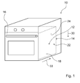
- FIG. 1 shows a trained as an oven cooking device 10.
- This has a cooking chamber 12, in which a cooking food to be heated is arranged.
- the cooking chamber 12 is bounded by means of a cooking chamber wall unit 14 shown schematically in the figure and, in the closed state shown, by means of a cooking chamber door 16 which closes a cooking chamber opening for introducing the food.
- the cooking chamber wall unit 14 comprises a cooking chamber bottom 18, which in a conventional Operation of the cooking appliance 10 by an end user is oriented substantially horizontally.
- the cooking chamber wall unit 14 has a rear wall 22 which forms a vertically aligned cooking chamber rear surface 24 arranged opposite the cooking chamber opening.
- the cooking space wall unit 14 includes side walls, each one in FIG. 2 form visible cooking chamber side surface 20.1 and 20.2, which extends vertically and perpendicular to the cooking space rear surface 24.
- the cooking chamber wall unit 14 is in FIG. 1 shown in a schematic view in which the cooking chamber 12 bounding Garraum lake are flat as surfaces of an idealized cuboid. Like in the FIG. 3 can be seen, these Garraum vom each have a relief, such as surveys and / or depressions have.
- the orientation of the corresponding planar cooking chamber surface of the simplified representation is under the orientation of a Garraum configuration FIG. 1 Understood.
- aligning a surface relative to a cooking chamber surface aligns the surface relative to the corresponding planar cooking chamber surface of the simplified illustration FIG. 1 Understood.
- the cooking chamber 12 is in a front view in FIG. 2 shown in more detail. There are the opposite Garraumen vom 20.1, 20.2, see the cooking space rear surface 24 and a parallel to the cooking chamber 18 aligned cooking chamber top surface 26.
- the cooking chamber 12 has three food support levels 28.1 to 28.3, which each extend parallel to the cooking chamber bottom 18 and arranged vertically above one another in the vertical direction 30 and are shown schematically in dashed lines in the figure.
- An intermediate food support level 28.2 is arranged above a lower cooking utensil level 28.1 directly facing the cooking chamber floor 18, and a upper food support level 28.3 directly facing the cooking chamber top surface 26 is arranged above the intermediate food support level 28.2.
- Gargutaebenen 28 each not shown in detail Gargutá, such as a baking tray or a grid can be arranged.
- the cooking appliance 10 is provided with three Garguta operationsakuen 32.1 to 32.3, which are each attached to the two opposite Garraumcondition vom 20.1, 20.2 and each associated with a food support level 28.1 to 28.3.
- the Garguta operationsakuen 32.1 to 32.3 are used to insert a food support in an insertion direction 33 which is aligned perpendicular to the cooking space rear surface 24.
- FIG. 2 shows the cooking chamber 12 in its basic installation position.
- the view shown corresponds to the view of the cooking chamber 12, as it can be perceived by an observing through the cooking chamber opening end user of the cooking appliance 10 under normal operating conditions.
- the cooking chamber side surfaces 20 and the cooking chamber rear surface 24 are vertically aligned.
- the cooking chamber bottom 18, the food support levels 28 and the cooking chamber top surface 26 are aligned horizontally.
- the terms "top”, “bottom”, “side”, etc. refer to this basic installation position shown in this text.
- the term “front” refers to the area of the cooking chamber opening. In particular, when inserting a food support in the cooking chamber 12 in the insertion direction 33 of the food support "pushed from front to back". Further, the terms “left” and “right” refer to the view of FIG FIG. 2 , in which the cooking chamber 12 is viewed from the cooking chamber opening.
- the cooking appliance 10 has a Garellagebläsevoriques, which is intended to blow a heated air flow in the cooking chamber 12, whereby the temperature in the cooking chamber 12 can be increased to a suitable cooking for a cooking temperature.
- the cooking appliance fan device has a cooking appliance fan device unit 34, of which a cooking chamber air passage unit 36 can be seen in the figure. This is provided for the production of an air exchange between the cooking chamber 12 and one of the cooking chamber opening from behind the cooking air passage unit 36 arranged heating chamber 38.
- the boiler room 38 is in FIG. 5 shown in more detail.
- the cooking chamber passage unit 36 has a wall unit 40 formed as a baffle wall, which is designed as a plate-shaped component made of sheet metal. This wall unit 40 is attached to the rear wall 22, such as by means of a screw connection, and forms in cooperation with the rear wall 22, the cooking space rear surface 24.
- the wall unit 40 is enclosed along its circumference by the rear wall 22 of the cooking space wall unit 14.
- suction openings 42 are recessed from the wall unit.
- suction openings 42 are recessed, which are provided for sucking an amount of air from the cooking chamber 12 out and into the heating chamber 38 inside.
- the suction openings 42 which in FIG. 3 are shown in detail, 24 are arranged centrally in the cooking space.
- the suction openings 42 are arranged in a suction region of the wall unit 40, which extends in a disk shape around the center of the cooking space rear surface 24.
- the diameter of the intake area is between a quarter and a half of the longitudinal extent of the wall unit 40th
- passage apertures 44, 48, 52 are cut out of the cooking-chamber passage unit 36, through which an air stream is blown into the cooking chamber 12 during a cooking appliance operation.
- the cooking chamber passage unit 36 has passage openings 44.1, 44.2, which are arranged in a lower half of the cooking space rear surface 24. These passage openings 44 are arranged in each case in the region of a vertical edge of the wall unit 40 on both sides of the suction openings 42.
- a passage opening is arranged "in the region" of an edge when it is arranged in a partial region of the wall unit 40, which is bounded by the edge and a parallel to the edge line of the wall unit 40, the distance to the edge of a maximum of a quarter of Longitudinal extent of the wall unit 40 has.
- passage openings 48.1, 48.2 provided in an upper half of the cooking space rear surface 24, which are also arranged in each case in the region of a vertical edge of the wall unit 40 on both sides of the suction openings 42.
- the pairs of passage openings 44 and 48 are separated by the projection of a food support level 28, in particular the intermediate food support level 28.2, in the horizontal direction on the cooking space rear surface 24. In this case, the pairs of passage openings 44, 48 are arranged on both sides of this projection line.
- this projection line corresponds to the horizontal bisector of the cooking chamber rear surface 24.
- the passage openings 48 are spaced from the passage openings 44 in the vertical direction 30. At least one air passage opening 44 or 48 is arranged in each quadrant of the cooking space rear surface 24.
- the passage openings 44.1, 44.2 are arranged symmetrically with respect to each other with respect to the vertical bisectors of the front of the wall unit 40 forming the cooking space rear surface 24.
- the passage openings 48.1, 48.2 are arranged symmetrically relative to one another with respect to these vertical side bisectors.
- the cooking chamber air passage unit 36 also has passage openings 52.1, 52.2, which are arranged in the region of the lower edge of the wall unit 40. Through these passage openings 52, an air circulation in a cooking region of the cooking chamber 12 is produced, which is arranged below the lower food support level 28.1.
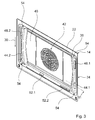
- FIG. 3 shows a perspective view of the rear wall 22 of the cooking chamber wall unit 14, on which the cooking chamber passage unit 36 is mounted.
- the wall unit 40 of the cooking chamber passage unit 36 is provided with fastening means 54, which are designed in particular as screw receptacles. These are mounted in a portion of the wall unit 40, which overlaps the rear wall 22 in the horizontal direction.
- the suction openings 42 are recessed. These are formed as a circular segment-shaped slots.
- Behind the intake openings 42 in the boiler room 38 is an in FIG. 5 illustrated blower body 66 is arranged.
- the passage openings 44, 48 can be seen, which are each designed as a vertically extending slot.
- the passage openings 52 in the lower edge region of the wall unit 40 each extend in the horizontal direction.
- the cooking appliance fan device In one operation of the cooking appliance fan device, air is sucked in centrally from the cooking chamber 12 through the suction openings 42 with respect to the cooking space rear surface 24 and, after being heated, is blown through the passage openings 44, 48, 52 into the cooking space 12.
- the cooking appliance fan device unit 34 is provided with an air guide unit 56, which serves to distribute a sucked amount of air to the passage openings 44, 48, 52.
- the air guide unit 56 and the distribution of the amount of air to the individual passage openings 44, 48, 52 within the heating chamber 38 are based on the FIGS. 4 and 5 described in more detail.
- FIG. 4 shows the air guide unit 56 of the Garellagebläsevoriquesstician 34 in a front view. This view is the same as the view FIG. 2 , The orientation of the air guiding unit 56 shown corresponds to the orientation of the in FIG. 2 To clarify this orientation, the cooking chamber bottom 18 is shown in dashed lines below the air guide unit 56.
- the air-guiding unit 56 In the mounted state, the air-guiding unit 56, viewed from the cooking chamber opening, is arranged behind the cooking-chamber air-permitting unit 36.
- the air guide unit 56 has a base wall 58, which is formed as a plate-shaped component made of sheet metal. This is in the assembly in one inserted on the rear wall 22 receiving portion 60 inserted (see FIG. 5 ).
- the base wall 58 has a plate surface 62 facing the cooking chamber 12, which has the orientation of the cooking space rear surface 24 in the mounted state of the cooking appliance 10. From the base wall 58, a circular opening is recessed, which serves as a receiving area 64 for receiving a in FIG. 5 shown blower body 66 is formed.
- the air baffle 56 further includes a set of baffles 68, 70, 72, 74, 76, 78 fixed to the plate surface 62.
- the Lucasleitwandept 68 to 78 are each formed as a wall part of sheet metal, which is perpendicular to the plate surface 62, ie in the basic installation position in the horizontal direction, rises.
- the Lucasleitwandungen 68 to 78 form a number of air channels 80, 82, 84, 86, 88, 90, each one of in FIG. 3 shown passage openings 44, 48, 52 of the cooking chamber passage unit 36 are assigned.
- a different air duct 88, 82, 90, 80, 84 and 86 is provided which serves to direct an air flow to this passage opening.
- the number of air passages of the air guide unit 56 corresponds to the number of passage openings of the cooking chamber air passage unit 36.
- the air passages 80 to 90 are respectively formed by the plate surface 62 of the base wall 58, two air guide walls of the set of air guide walls 68 to 78 and the cooking chamber air passage unit 36.
- the plate surface 62 and the cooking chamber air passage unit 36 serve as a rear wall or front wall of the air ducts 80 to 90, while a Heilleitwandung serves as a vertical to the rear wall and front wall side guide for at least one of the air ducts 80 to 90.
- at least one air channel 80, 82, 84, 86, 88 or 90 is formed in each quadrant of the plate surface 62.
- the air guide unit 56 has a first, top air guide wall 68, which is arranged above the receiving area 64. It extends from a first, left side edge 92 of the base wall 58 to a second, the first side edge 92 opposite the right side edge 94 of the base wall 58.
- the Luftleitwandung 68 may be executed interrupted.
- the air guide wall 68 has a straight section 68.1, which, starting from the first side edge 92, extends horizontally in the direction of the receiving region 64. This section 68.1 merges into a curved section 68.2.
- This section 68.2 extends above the receiving area 64 parallel to the circumference of the circular receiving area 64 over an angular range of about 90 °.
- the curved section 68.2 merges into a straight section 68.3, which extends horizontally in the direction of the second side edge 94.
- the baffle 68 extends from the upper left quadrant to the upper right quadrant of the plate surface 62.
- the air guide unit 56 has five further air guide walls 70 to 78 which, starting from the first, uppermost air guide wall 68, are described around the receiving area 64 in the counterclockwise direction.
- the air guide unit 56 is provided with a second, intermediate air guide wall 70 which is fixed in the upper half and in the lower half of the plate surface 62. It has an outgoing from the side edge 92 and extending in the direction of the receiving portion 64 straight portion 70.1, which is offset relative to the straight portion 68.1 of the first Beerleitwandung 68 over a distance S in the vertical direction 30 down and parallel to this.
- This section 70.1 merges into another straight section 70.2, which forms an obtuse angle to the straight section 70.1.
- This continues in a section 70.3 which runs parallel to the circumference of the receiving region 64.
- This section 70.3 is followed by another section 70.4, which extends in the direction of the side edge 92 in the horizontal direction.
- the air guide unit 56 has a third air guide wall 72, which is fastened in the lower left quadrant of the plate surface 62.
- This Gutleitwandung 72 has a starting from the side edge 92 and extending in the direction of the receiving portion 64 straight portion 72.1, which is offset relative to the straight portion 70.4 of the second shipsleitwandung 70 over a distance T in the vertical direction downwards and parallel thereto. This merges into a curved section 72.2, which extends bent in the direction of a lower edge 96 of the base wall 58.
- the second Heilleitwandung 70 forms in cooperation with the first Luftleitwandung 68, a first air passage 80, which is for directing an air flow to the passage opening 48.2 (see Figures 2 and 3 ) is provided.
- the Heilleitwandungen 68, 70 each serve as a side guide of the air channel 80.
- the main extension direction of the straight sections 68.1, 70.1 which corresponds to the longitudinal direction of the sections 68.1, 70.1, there a straight main extension direction of the air duct 80, which is aligned horizontally.
- the flow direction of the air channel 80 is aligned horizontally.
- the second Heilleitwandung 70 forms in cooperation with the third shipsleitwandung 72 a second air channel 82, which is provided for directing an air flow to the passage opening 44.2.
- the Heilleitwandungen 70, 72 namely the sections 70.4 and 72.1, each serve as a lateral guide of the air channel 82, which thus has a horizontal main extension direction.
- the Heilleitwandung 70 which is designed as a one-piece component, serves as a side guide 98 of the first air passage 80 and as a side guide 100 of the second air channel 82nd
- the distances S and T correspond to the vertical extension of the air duct 80 and 82, respectively. They may be identical or different. In the embodiment shown, the distance S is greater than the distance T formed. The distances S and T also correspond to the vertical extent of the slot-shaped openings 48.2 and 44.2.
- the third Gutleitwandung 72 forms in cooperation with a fourth Heilleitwandung 74 an air passage 84 which is provided for guiding an air flow to the passage opening 52.1 and a vertically downward flow direction.
- the fourth air guide wall 74 has a main portion 74. 1, which is arranged to the right of the third air guide wall 72 and extends parallel to the circumference of the receiving area 64. Further, the main portion 74.1 extends from the lower left quadrant to the lower right quadrant of the plate surface 62. Both ends of the main portion 74.1 merge into a downwardly directed portion 74.2 and 74.3, respectively extending at least to the lower edge 96 of the base wall 58.
- the air guide unit 56 is further provided with a fifth Heilleitwandung 76, which forms an air passage 86 in cooperation with the right portion 74.3 of the fourth shipsleitwandung 74, which serves to direct an air flow to the passage opening 52.2 and a vertically downward flow direction.
- the fifth baffle 76 is attached to the right of the fourth baffle 74 in the lower right quadrant of the plate surface 62 and has a first portion 76.1 which extends vertically upward from the lower edge 96 of the base 58. This section 76.1 follows a horizontally oriented section 76.2, which runs in the direction of the right side edge 94 of the base wall 58.
- This straight section 76.2 of the fifth Lucasleitwandung 76 serves as a side guide of an air channel 88, which serves to direct an air flow to the passage opening 44.1. This is done in cooperation with a sixth Heilleitwandung 78, which has a parallel to the section 76.2 of the fifth Heilleitwandung 76 extending straight section 78.1.
- the air channel 88 has over its entire length a straight main extension direction, which defines a horizontally oriented flow direction for an air flow to the passage opening 44.1.
- the section 78.1 of the baffle 78 which serves as a lateral guide of the air duct 88, merges into a curved section 78.2, which extends parallel to the circumference of the receiving area 64 over the lower half and the upper half of the plate surface 62.
- This section 78.2 merges into a straight and horizontally oriented section 78.3 that extends toward the right side edge 94.
- the sixth Heilleitwandung 78 which is formed as a one-piece component, also serves as a side guide of an air passage 90, which is provided for directing an air flow to the passage opening 48.1.
- This air duct 90 is formed by the portion 78.3 in cooperation with the horizontal portion 68.3 of the first Heilleitwandung 68.
- the air channel 90 has a main extension direction, which is aligned horizontally.
- the shipsleitwandiers 68 to 78 each have a portion 102 which extends beyond the edge of the base wall 58 also and serves to rest against the rear wall 22, as the FIG. 5 can be seen.
- blown air heating element 104 designed as a heating element is also provided. This is designed as a tubular body, which is wound around the receiving region 64 in the mounted state of the cooking appliance 10.
- the radiator 104 penetrates the base wall 58 through two openings which are recessed in the upper left quadrant of the plate surface 62.
- the arrangement of the radiator 104 in the assembled state of the cooking appliance 10 is shown schematically by dashed lines.
- FIG. 5 shows the rear wall 22 of the cooking chamber wall unit 14 and the air guide unit 56 in the perspective view of FIG. 3 ,
- FIG. 5 shown arrangement corresponds to in FIG. 3 shown arrangement in which the cooking chamber passage unit 36 has been removed.
- An embodiment variant of the air-guiding unit 56 is shown, the only in the design of the Lucasleitwandungen and the arrangement of the connection points of the radiator 104 in the lower right quadrant of the plate surface 62 of the in FIG. 4 shown embodiment differs.
- the rear wall 22 forms a receiving area 60, in which the air guiding unit 56 is arranged.
- the receiving area 60 is a recessed area relative to the cooking space rear surface 24, which is rectangular in shape.
- the rear wall 22 has a first surface portion 106, which extends vertically in the basic installation position and is provided for placing the cooking chamber passage unit 36. Adjoining this portion 106 is a rearwardly extending bevel 108, which forms an angle with the surface portion 106 and is oriented vertically in the basic installation position. Thus, an edge 110 of the rear wall 22 is formed, which surrounds the receiving area 60. This edge 110 may be an angular or a rounded edge.
- the slope formed by the rear wall 22 serves in the air ducts 80 to 90 as deflection means 114, which serves to deflect a guided in the corresponding air duct air flow before it passes through a passage opening 44, 48 or 52.
- the air channels 80, 82, 88, 90 have a main extension, which is aligned horizontally and parallel to the cooking chamber rear surface 24 in the basic installation position. This main extension is aligned horizontally and perpendicular to the insertion direction 33.
- the deflection means 114 in the air ducts 80, 82, 88, 90 is designed to predetermine a passage direction 116 for the air flow guided in the corresponding air duct into which the air flow passes through the passage opening 48.2, 44.2, 44.1 or 48.1 of the cooking chamber passage unit 36 corresponding to the air passage flows (see FIG. 6 ).
- the deflection means 114 each provide a passage direction 116, which is oriented horizontally counter to the insertion direction 33. The principle of air flow and deflection is based on FIG. 6 described in more detail.
- FIG. 3 illustrates a view of the heating chamber 38, which is bounded by the base wall 58, the rear wall 22 of the cooking chamber wall unit 14 and the cooking chamber air passage unit 36 in the mounted state of the cooking appliance fan device.
- the heating chamber 38 has air flow-free spaces 118 which are inaccessible to an air flow generated by the fan body 66. These airflow-free spaces 118 are formed by the base wall 58, the cooking chamber air passage unit 36 and by an interaction of one of the Lucasleitwandept 68 to 78 with the rear wall 22, with the slope 108. In particular, one of the air guide walls 68 to 78, in cooperation with the bevel 108, respectively encloses an air-flow-free space 118.
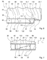
- FIG. 6 shows a sectional view of the Garellagebläsevoriquessech 34 along a line VI in FIG. 3 ,
- the principle of air flow and deflection is explained using the example of the air duct 88.
- the following description also applies to the further air ducts of the air duct unit 56.
- the cooking chamber 12 which is bounded by the cooking chamber wall unit 14, which has the cooking chamber side surface 20.1 and the rear wall 22, and the cooking chamber air passage unit 36 with the wall unit 40.
- the rear wall 22 and the wall unit 40 form the cooking space rear surface 24.
- the receiving area 60 can be seen, which is formed as a recess of the rear wall 22 to the rear.
- the air guide unit 56 is received.
- the base wall 58 is inserted in the receiving area 60.
- the passage opening 44.1 of the cooking chamber passage unit 36 (see Figures 2 and 3 ) left out.
- the air guide unit 56, the air duct 88 (see also FIG. 4 ), which has a horizontal in the basic installation position and perpendicular to the insertion direction 33 main extension direction.
- This straight main extension direction defines a flow direction 120 of the air channel 88. It is the side guide of the air duct 88 forming Vietnameseleitwandung 78, namely to see the straight section 78.1.
- the air duct 88 extends uninterrupted to the passage opening 44.1, and that opens into the passage opening 44.1.
- the air channel 88 serves to generate an air flow generated by the fan body 66 in the main direction of extension of the air channel 88 horizontally and perpendicular to the insertion direction 33 rectify.
- the air flow flowing in the direction of flow 120 is then deflected by means of the deflection means 114, which is formed by the slope 108 of the rear wall 22, in the passage direction 116, which is oriented horizontally counter to the insertion direction 33.
- the air flow flows into the cooking chamber 12 in a direction which is aligned parallel to the cooking chamber side surfaces 20.
- the air guiding unit 56 also has a fluid 122 which forms a transverse surface 124 projecting into the air passage 88.
- the fluid 122 is based on the FIGS. 7 and 8th described in more detail.
- FIG. 7 shows the air duct 88 in a sectional view taken along the line VII-VII in FIG FIG. 6 ,
- the air duct 88 is fixed by means of the base wall 58, the wall unit 40 and the Lucasleitwandept 76, 78, namely the straight sections 78.1, 76.2, which are perpendicular to the plate surface 62 of the base wall 58 perpendicular.
- the fluid 122 forms the transverse surface 124, which is oriented perpendicular to the flow direction 120 of the air channel 88.
- the transverse surface 124 in the basic installation position is aligned vertically and parallel to the cooking chamber side surfaces 20.
- the transverse surface 124 has a contour which varies in the air duct cross section. In particular, the transverse surface 124 has a stepped contour.
- the transverse surface 124 forms a blocking surface for blocking the air duct 88, which in the basic installation position has a contour which varies with respect to a first coordinate of the air duct cross section. Therefore, the transverse surface 124 has a varying extent along a second coordinate of the air duct cross-section.
- the first coordinate is assigned to the vertical direction 30 in the embodiment shown and in the basic installation position.
- the second coordinate is assigned to a horizontal direction.
- the transverse surface 124 has an extension in the horizontal direction, which varies along the vertical direction 30.
- the transverse surface 124 comprises a locking surface which bears against the air guide wall 78 forming the upper side guide of the air duct 88 and has the maximum extension with respect to the second coordinate.
- a blocking surface which is the minimum extension with respect to the second Coordinate has.
- the transverse surface 124 serves, in particular, to compensate for inhomogeneities in the flow velocity of the air stream before passing through the passage opening 44.1.
- FIG. 8 is a perspective view of the cooking chamber passage unit 36 with the passage opening 44.1 shown. It can be seen the rear surface 126 of the cooking chamber passage unit 36, which faces the base wall 58 of the air guide unit 56 in the assembled state of the cooking appliance 10.
- the fluid 122 is attached to the cooking chamber air passage unit 36, in particular on the rear surface 126 thereof. It is designed as a wall part which extends parallel to the longitudinal extent of the passage opening 44.1. In an alternative embodiment, the fluid 122 may be attached to the air guide unit 56.
- the fluid 122 is arranged in the edge region of the passage opening 44.1. In particular, the fluid 122 connects to an edge of the passage opening 44.1, to a passage opening edge extending vertically in the basic installation position.
- FIG. 9 shows a sectional view through the air passage 82.
- a fluid 128 is arranged, which forms a projecting in the air passage 82 transverse surface 130.
- the transverse surface 130 differs from the transverse surface 124 by the configuration of its contour.
- the transverse surface 130 forms a blocking surface, which rests against the air guide wall 70 forming the upper side guide of the air channel 82. This blocking surface extends over a fraction of the vertical cross-sectional extension of the air channel 82 and leaves the remaining portion of the air channel cross section for a flow of air flow completely free.
Abstract
Description
Die Erfindung geht aus von einer Gargerätegebläsevorrichtungseinheit nach dem Oberbegriff des Anspruchs 1.The invention is based on a cooking appliance fan device unit according to the preamble of claim 1.
Es ist eine Gebläsevorrichtung für einen Backofen bekannt, die zum Heizen eines Backraums mittels eines Blasens einer erwärmten Luft in den Backraum vorgesehen ist.There is known a fan device for an oven, which is provided for heating a baking chamber by means of a blowing of a heated air in the baking chamber.
Die Aufgabe der Erfindung besteht insbesondere darin, eine Gargerätegebläsevorrichtungseinheit für eine gattungsgemäße Gebläsevorrichtung mit verbesserten Eigenschaften hinsichtlich von Strömungsverhältnissen in einem Garraum bereitzustellen.The object of the invention is in particular to provide a Gargerätegebläsevorrichtungseinheit for a generic blower device with improved properties in terms of flow conditions in a cooking chamber.
Die Aufgabe wird erfindungsgemäß durch die Merkmale des Patentanspruchs 1 gelöst, während vorteilhafte Ausgestaltungen und Weiterbildungen der Erfindung den Unteransprüchen entnommen werden können.The object is achieved by the features of claim 1, while advantageous embodiments and modifications of the invention can be taken from the dependent claims.
Es wird eine Gargerätegebläsevorrichtungseinheit vorgeschlagen, die eine Luftleiteinheit aufweist, welche zum Leiten eines Luftstroms zu wenigstens einer Durchlassöffnung einer Garraumluftdurchlasseinheit vorgesehen ist. Unter einer "Garraumluftdurchlasseinheit" soll in diesem Zusammenhang insbesondere eine Einheit verstanden werden, die zum Durchlassen eines in einen Garraum einzublasenden Luftstroms vorgesehen ist. Insbesondere bildet die Garraumluftdurchlasseinheit im montierten Zustand eines Garraums eine den Garraum begrenzende Garraumfläche, wobei die Durchlassöffnung direkt in den Garraum mündet. Durch die Luftleiteinheit können vorteilhafte Strömungsverhältnisse im Garraum erreicht werden. Insbesondere kann ein Blasen eines Luftstroms durch die Durchlassöffnung in den Garraum in eine bevorzugte Durchlassrichtung erreicht werden.There is proposed a Gargerätegebläsevorrichtungseinheit having an air guide unit, which is provided for guiding an air flow to at least one passage opening of a cooking chamber air passage unit. In this context, a "cooking chamber passage unit" should be understood as meaning, in particular, a unit which is provided for passing an air stream to be injected into a cooking chamber. In particular, in the mounted state of a cooking chamber, the cooking chamber passage unit forms a cooking space bounding the cooking space, wherein the passage opening opens directly into the cooking space. By the air guide unit advantageous flow conditions can be achieved in the oven. In particular, a blowing of an air flow through the passage opening into the cooking chamber in a preferred passage direction can be achieved.
In einer bevorzugten Ausführung der Erfindung wird vorgeschlagen, dass die Gargerätegebläsevorrichtungseinheit eine Garraumluftdurchlasseinheit umfasst, die eine Wandeinheit aufweist, welche dazu vorgesehen ist, eine einen Garraum begrenzende Garraumhinterfläche zu bilden, aus welcher eine Durchlassöffnung ausgespart ist. Unter einer "Garraumhinterfläche" soll in diesem Zusammenhang insbesondere eine Fläche verstanden werden, die im zusammengebauten Zustand des Garraums gegenüber einer Garraumöffnung zum Einführen einer zu erwärmenden Speise in den Garraum angeordnet ist. Insbesondere ist die Garraumhinterfläche senkrecht zu einer Einschubrichtung zum Einschieben eines Gargutträgers in den Garraum ausgerichtet. Gemäß einer bevorzugten Konstruktion ist die Garraumluftdurchlasseinheit dazu vorgesehen, einen Gebläsekörper zum Erzeugen eines Luftstroms zu bedecken. Hierbei weist die Garraumhinterfläche vorzugsweise zumindest eine Öffnung zum Ansaugen von Luft aus dem Garraum auf. Durch die Aussparung einer Durchlassöffnung in der Garraumhinterfläche können besonders vorteilhafte Garergebnisse erreicht werden.In a preferred embodiment of the invention, it is proposed that the cooking appliance fan device unit comprises a cooking chamber air passage unit which has a wall unit which is provided to form a cooking chamber rear surface delimiting a cooking space from which a passage opening is recessed. In this context, a "cooking space rear surface" should be understood as meaning, in particular, an area be arranged in the assembled state of the cooking chamber with respect to a cooking chamber opening for introducing a food to be heated in the oven. In particular, the cooking space rear surface is aligned perpendicular to an insertion direction for insertion of a food support in the cooking chamber. According to a preferred construction, the cooking chamber air passage unit is provided to cover a fan body for generating an air flow. In this case, the cooking space rear surface preferably has at least one opening for sucking in air from the cooking space. Due to the recess of a passage opening in the cooking space rear surface particularly advantageous cooking results can be achieved.
Außerdem wird vorgeschlagen, dass die Luftleiteinheit wenigstens zwei Luftkanäle zu zumindest zwei Durchlassöffnungen einer Garraumluftdurchlasseinheit aufweist, wodurch eine besonders effektive Hitzeverteilung in einem Garraum erreicht werden kann. Unter einem Luftkanal "zu" einer Durchlassöffnung soll in diesem Zusammenhang insbesondere ein Luftkanal verstanden werden, der in die Durchlassöffnung mündet. Hierbei schließt sich vorteilhafterweise eine den Luftkanal bildende Luftleitwandung an einen Öffnungsrand der Durchlassöffnung an.It is also proposed that the air guiding unit has at least two air ducts to at least two passage openings of a cooking chamber passage unit, whereby a particularly effective heat distribution in a cooking chamber can be achieved. An air duct "to" a passage opening is to be understood in this context, in particular an air duct, which opens into the passage opening. This advantageously joins an air duct forming the air duct to an opening edge of the passage opening.
Insbesondere kann eine hohe Homogenität bezüglich einer Temperaturverteilung im Garraum erreicht werden, wenn die Gargerätegebläsevorrichtungseinheit eine Garraumluftdurchlasseinheit umfasst, die eine Mehrzahl von Durchlassöffnungen aufweist, und wenn für zumindest eine überwiegende Anzahl von Durchlassöffnungen ein Luftkanal zur Leitung eines Luftstroms zu jeweils einer Durchlassöffnung vorgesehen ist. Unter einer "überwiegenden Anzahl" von Durchlassöffnungen soll in diesem Zusammenhang eine Anzahl verstanden werden, welche zumindest die Hälfte, vorteilhaft zumindest drei Viertel und bevorzugt zumindest neun Zehntel der gesamten Anzahl von Durchlassöffnungen der Garraumluftdurchlasseinheit darstellt. Besonders vorteilhaft ist es, wenn für jede Durchlassöffnung der Garraumluftdurchlasseinheit jeweils ein unterschiedlicher Luftkanal der Luftleiteinheit vorgesehen ist. Bevorzugterweise weist die Garraumluftdurchlasseinheit zumindest vier Durchlassöffnungen auf, um einen besonders effektiven Garbetrieb zu erreichen.In particular, a high homogeneity with respect to a temperature distribution in the cooking chamber can be achieved if the cooking appliance blower unit comprises a cooking chamber passage unit having a plurality of passage openings, and if for at least a majority of passage openings, an air passage for directing an air flow to each passage opening is provided. In this context, a "predominant number" of passage openings should be understood to mean a number which represents at least half, advantageously at least three quarters and preferably at least nine tenths of the total number of passage openings of the cooking chamber passage unit. It is particularly advantageous if, in each case, a different air duct of the air-guiding unit is provided for each passage opening of the cooking chamber air passage unit. The cooking chamber passage unit preferably has at least four passage openings in order to achieve a particularly effective cooking operation.
Ferner wird vorgeschlagen, dass die Luftleiteinheit zumindest einen Luftkanal aufweist, der dazu vorgesehen ist, eine Durchlassrichtung für einen Luftstrom durch eine Durchlassöffnung einer Garraumluftdurchlasseinheit vorzugeben, die in einer Grundeinbaustellung im Wesentlichen horizontal ausgerichtet ist, wodurch eine auf ein verbessertes Garergebnis gerichtete Lufteinlassung in einen Garraum einfach erreicht werden kann. Unter der Ausrichtung einer Richtung in einer "Grundeinbaustellung" soll in diesem Zusammenhang insbesondere eine Ausrichtung verstanden werden, die bei einer Anwendung eines Gargeräts, bei welchem die erfindungsgemäße Gargerätegebläsevorrichtungseinheit eingesetzt ist, unter üblichen Anwendungsbedingungen vorliegt. Insbesondere ist die Durchlassrichtung parallel zu einem Garraumboden ausgerichtet, welcher in der Grundeinbaustellung horizontal orientiert ist. Des Weiteren beziehen sich die Begriffe "oben", "unten", "vorne", "hinten" usw. in diesem Text auf diese Grundeinbaustellung. Außerdem soll unter einer Richtung, die "im Wesentlichen" horizontal ausgerichtet ist, insbesondere eine Richtung verstanden werden, die einen spitzen Winkel von maximal 15°, insbesondere maximal 10° und besonders bevorzugt maximal 5° mit einer horizontalen Ebene bildet. Ferner soll unter einer "Durchlassrichtung" für einen Luftstrom durch eine Durchlassöffnung insbesondere eine Richtung verstanden werden, in welche der Luftstrom durch die Durchlassöffnung strömt.It is further proposed that the air guiding unit has at least one air duct, which is provided, a passage direction for an air flow through a passage opening a Garraumluftdurchlasseinheit pretend, which is oriented substantially horizontally in a basic installation position, whereby a directed to an improved cooking result air inlet into a cooking chamber can be easily achieved. The orientation of a direction in a "basic installation position" should be understood in this context, in particular, an orientation that is present in an application of a cooking appliance, in which the Gargerätegebläsevorrichtungseinheit invention is used under normal conditions of use. In particular, the passage direction is aligned parallel to a cooking chamber floor, which is oriented horizontally in the basic installation position. Furthermore, the terms "top", "bottom", "front", "rear" etc. in this text refer to this basic installation position. In addition, under a direction which is oriented "substantially" horizontally, in particular a direction is to be understood which forms an acute angle of at most 15 °, in particular at most 10 ° and particularly preferably at most 5 ° with a horizontal plane. Furthermore, a "passage direction" for an air flow through a passage opening is to be understood in particular a direction in which the air flow flows through the passage opening.
In einer vorteilhaften Weiterbildung der Erfindung wird vorgeschlagen, dass die Luftleiteinheit zumindest einen Luftkanal aufweist, der über zumindest einen wesentlichen Teil der Länge des Luftkanals einen Luftkanalabschnitt mit einer geraden Haupterstreckung aufweist, die eine im Wesentlichen horizontal ausgerichtete Strömungsrichtung für einen Luftstrom festlegt. Dadurch kann ein vorteilhaftes Gleichrichten eines Luftstroms in horizontaler Richtung vor dessen Durchlassen in einen Garraum konstruktiv einfach erreicht werden. Unter einem "Luftkanalabschnitt mit einer geraden Haupterstreckung", soll in diesem Zusammenhang insbesondere ein Luftkanalabschnitt verstanden werden, bei welchem Querschnittsflächen zu beliebigen Punkten des Luftkanalabschnitts die gleiche Ausrichtung aufweisen. Hierdurch legt der Luftkanalabschnitt eine über den Luftkanalabschnitt einheitliche Strömungsrichtung für einen Luftstrom fest, welche der zu den Querschnittsflächen senkrecht stehenden Richtung entspricht. Unter einem "wesentlichen Teil" der Länge des Luftkanals soll in diesem Zusammenhang insbesondere zumindest 50 %, vorteilhaft zumindest 75 % und bevorzugt zumindest 90 % der gesamten Länge des Luftkanals verstanden werden. Um eine besonders vorteilhafte Warmluftverteilung in einem Garraum zu erreichen, weist die Luftleiteinheit vorzugsweise zumindest vier Luftkanäle auf, die jeweils über zumindest einen wesentlichen Teil ihrer Länge des Luftkanals einen Luftkanalabschnitt mit einer geraden Haupterstreckung aufweisen, die eine im Wesentlichen horizontal ausgerichtete Strömungsrichtung für einen Luftstrom festlegt.In an advantageous development of the invention, it is proposed that the air guiding unit has at least one air duct which has an air duct section with a straight main extension over at least a substantial part of the length of the air duct, which defines a substantially horizontally oriented flow direction for an air flow. As a result, an advantageous rectification of an air flow in the horizontal direction before its passage into a cooking chamber can be achieved in a structurally simple manner. An "air duct section with a straight main extension" is to be understood in this context in particular as an air duct section in which cross-sectional areas at any points of the air duct section have the same orientation. As a result, the air duct section defines a flow direction, which is uniform over the air duct section, for an air flow which corresponds to the direction perpendicular to the cross-sectional surfaces. In this context, a "substantial part" of the length of the air duct should in particular be understood to mean at least 50%, advantageously at least 75%, and preferably at least 90%, of the entire length of the air duct. In order to achieve a particularly advantageous distribution of hot air in a cooking chamber, the air guiding unit preferably has at least four air ducts, each having at least a substantial part of its length of the air duct Air duct section having a straight main extension, which defines a substantially horizontally oriented flow direction for an air flow.
In einer vorteilhaften Ausbildung der Erfindung wird vorgeschlagen, dass die Gargerätegebläsevorrichtungseinheit eine Garraumluftdurchlasseinheit umfasst, die zumindest zwei Durchlassöffnungen aufweist, die in einer Grundeinbaustellung betrachtet in vertikaler Richtung beabstandet sind, wodurch eine effektive Verteilung einer in einen Garraum eingeblasenen Luft erreicht werden kann. Unter zwei Durchlassöffnungen, die "in vertikaler Richtung beabstandet" sind, sollen zwei Durchlassöffnungen verstanden werden, für welche eine horizontal ausgerichtete Ebene gedacht werden kann, wobei die Durchlassöffnungen beidseitig der Ebene angeordnet sind.In an advantageous embodiment of the invention, it is proposed that the cooking appliance fan device unit comprises a cooking chamber air passage unit which has at least two passage openings, which are viewed in a basic installation position spaced in the vertical direction, whereby an effective distribution of a blown into a cooking chamber air can be achieved. Two passage openings which are "vertically spaced" are to be understood as meaning two passage openings, for which a horizontally oriented plane can be imagined, the passage openings being arranged on both sides of the plane.
Eine besonders vorteilhafte Luftverteilung im Garraum kann erreicht werden, wenn die Garraumluftdurchlasseinheit eine Wandeinheit aufweist, welche dazu vorgesehen ist, eine einen Garraum begrenzende Garraumfläche zu bilden, und welche zumindest vier Durchlassöffnungen umfasst, die jeweils in einem unterschiedlichen Quadrant der Garraumfläche angeordnet sind.A particularly advantageous air distribution in the cooking chamber can be achieved if the cooking chamber passage unit has a wall unit which is provided to form a cooking chamber defining a cooking space, and which comprises at least four passage openings, which are each arranged in a different quadrant of Garraumfläche.
Des Weiteren wird vorgeschlagen, dass eine erste Durchlassöffnung zum Ausblasen eines Luftstroms in einen ersten Garbereich eines Garraums und eine zweite Durchlassöffnung zum Ausblasen eines Luftstroms in einen zweiten Garbereich eines Garraums vorgesehen sind und dass die Garbereiche durch zumindest eine Gargutträgerebene getrennt sind. Durch die Luftleiteinheit kann in diesem Zusammenhang vorteilhaft eine gleichmäßige Wärmeverteilung auf verschiedene Garbereiche erreicht werden. Unter einer "Gargutträgerebene" soll insbesondere eine Ebene des Garraums verstanden werden, in welcher ein Gargutträger bei einem Garbetrieb angeordnet sein kann. Diese Ebene ist vorzugsweise von einem Halte- und/oder Führungsmittel zum Halten und/oder Führen des Gargutträgers in der Ebene festgelegt.Furthermore, it is proposed that a first passage opening for blowing out an air flow into a first cooking area of a cooking chamber and a second passage opening for blowing out an air flow into a second cooking area of a cooking space are provided and that the cooking areas are separated by at least one food support level. In this context, the air-conduction unit can advantageously achieve a uniform distribution of heat to different cooking areas. A "food support level" is to be understood in particular a level of the cooking space, in which a food support can be arranged in a cooking operation. This level is preferably determined by a holding and / or guiding means for holding and / or guiding the food support in the plane.
In einer bevorzugten Weiterbildung der Erfindung wird vorgeschlagen, dass ein Aufnahmebereich zur Aufnahme eines rotatorischen Gebläsekörpers vorgesehen ist und die Luftleiteinheit zumindest eine Luftleitwandung aufweist, welche sich in Rotationsrichtung eines aufgenommenen Gebläsekörpers gebogen erstreckt. Besonders vorteilhaft können unerwünschte, durch eine Drallwirkung des Gebläsekörpers hervorgerufene Stromverhältnisse vermindert werden. Diese können besonders effektiv vermindert werden, wenn die Luftleitwandung sich an einen Luftkanal zu einer Durchlassöffnung einer Garraumluftdurchlasseinheit anschließt. Hierbei kann ein Luftstrom in unmittelbarer Nähe des Gebläsekörpers erfasst werden. Durch die Reduktion von Turbulenzen kann ferner ein hoher Wirkungsgrad bei einem Garbetrieb erreicht werden, wodurch der Einsatz von Motoren mit niedriger Leistung und mit geringer Drehzahl ermöglicht wird.In a preferred embodiment of the invention, it is proposed that a receiving area for receiving a rotary blower body is provided and the air-guiding unit has at least one spoiler wall, which extends bent in the direction of rotation of a recorded blower body. Particularly undesirable, caused by a swirl effect of the fan body current conditions be reduced. These can be reduced in a particularly effective manner if the air conduction wall adjoins an air duct to a passage opening of a cooking chamber air passage unit. In this case, an air flow in the immediate vicinity of the fan body can be detected. By reducing turbulence, moreover, a high efficiency in a cooking operation can be achieved, whereby the use of low-power and low-speed engines is made possible.
Eine kompakte Ausführung der Luftleiteinheit kann ferner erreicht werden, wenn die Luftleiteinheit eine Grundwandung und zumindest eine sich von der Grundwandung erhebende einteilige Luftleitwandung aufweist, die im Zusammenwirken mit der Grundwandung zur Bildung von zumindest zwei Luftkanälen dient. Die Grundwandung bildet vorteilhafterweise eine Stützfläche, insbesondere eine plattenförmige Stützfläche, die zum Abstützen der Luftleitwandung und insbesondere von zumindest einer zweiten Luftleitwandung dient.A compact embodiment of the air guiding unit can furthermore be achieved if the air guiding unit has a base wall and at least one one-piece spoiler wall which rises from the base wall and cooperates with the base wall to form at least two air ducts. The base wall advantageously forms a support surface, in particular a plate-shaped support surface, which serves to support the Luftleitwandung and in particular of at least a second Luftleitwandung.
Eine besonders kompakte Konstruktion kann erreicht werden, wenn die Gargerätegebläsevorrichtungseinheit eine Garraumwandungseinheit umfasst, die dazu vorgesehen ist, einen Garraum zu begrenzen, und die einen Aufnahmebereich aufweist, der zur Aufnahme der Luftleiteinheit vorgesehen ist. Vorzugweise bildet die Garraumwandungseinheit im Zusammenwirken mit einer die Luftleiteinheit bedeckenden Garraumluftdurchlasseinheit eine Garraumhinterfläche. Insbesondere kann die Garraumluftdurchlasseinheit von der Garraumwandungseinheit umgeben, bevorzugt vollständig umgeben sein. Der Aufnahmebereich kann beispielsweise eine aus der Garraumwandungseinheit ausgesparte Öffnung oder eine aus der Garraumwandungseinheit ausgeformte Vertiefung sein.A particularly compact construction can be achieved if the cooking appliance fan device unit comprises a cooking chamber wall unit which is intended to delimit a cooking chamber and which has a receiving region which is provided for receiving the air guide unit. The cooking chamber wall unit preferably forms a cooking chamber rear surface in cooperation with a cooking chamber passage unit covering the air guiding unit. In particular, the cooking chamber passage unit can be surrounded by the cooking chamber wall unit, preferably completely surrounded. The receiving region can be, for example, an opening recessed from the cooking chamber wall unit or a cavity formed from the cooking chamber wall unit.
In diesem Zusammenhang kann eine einfache Montage erreicht werden, wenn die Luftleiteinheit eine Grundwandung aufweist, welche im montierten Zustand im Aufnahmebereich eingelegt ist und an welcher Luftleitwandungen zur Bildung von Luftkanälen befestigt sind. Zweckmäßigerweise grenzt die Grundwandung im Zusammenwirken mit einer Garraumluftdurchlasseinheit einen Heizraum ein, in welchem im montierten Zustand zumindest ein Heizkörper und ein Gebläsekörper angeordnet sind.In this context, a simple assembly can be achieved if the air guide unit has a base wall, which is inserted in the mounted state in the receiving area and are attached to which Luftleitwandungen to form air ducts. Expediently, the base wall, in cooperation with a cooking chamber passage unit, delimits a heating space in which, in the installed state, at least one heating element and one fan body are arranged.
Ferner wird vorgeschlagen, dass die Garraumwandungseinheit ein Umlenkmittel zum Umlenken eines Luftstroms vor dessen Durchlassen durch eine Durchlassöffnung bildet.It is also proposed that the cooking chamber wall unit forms a deflection means for deflecting an air flow before it passes through a passage opening.
Durch das Nutzen der Garraumwandungseinheit zum Umlenken des Luftstroms kann auf zusätzliche Umlenkmittel verzichtet werden und es kann Bauraum eingespart werden.By using the cooking chamber wall unit for deflecting the air flow can be dispensed with additional deflection and it can be saved space.
Eine kompakte Konstruktion und ein Einsparen von Bauteilen können außerdem erreicht werden, wenn die Luftleiteinheit zumindest eine einteilige Luftleitwandung aufweist, die im montierten Zustand im Zusammenwirken mit der Garraumwandungseinheit einen luftstromfreien Raum festlegt.A compact design and a saving of components can also be achieved if the air guide unit has at least one one-piece Luftleitwandung that defines an airflow-free space in the assembled state in cooperation with the cooking chamber wall unit.
In einer weiteren Ausbildung der Erfindung wird vorgeschlagen, dass die Luftleiteinheit zumindest einen Luftkanal zum Leiten eines Luftstroms und ein Strömungsmittel aufweist, welches eine im Luftkanal angeordnete Querfläche bildet. Unter einer "Querfläche" soll in diesem Zusammenhang insbesondere eine Fläche verstanden werden, welche, wenn sie auf die den Mittelpunkt des Strömungsmittels einschließende Querschnittfläche des Luftkanals projiziert wird, eine zweidimensionale Erstreckung aufweist. Hierbei bildet die Querfläche mit dieser Querschnittfläche einen Winkel, der maximal 45°, vorteilhaft maximal 20° und bevorzugt maximal 10° beträgt. Besonders vorteilhaft weisen die Querfläche und die Querschnittsfläche die gleiche Ausrichtung auf. Unter einem "Strömungsmittel" soll in diesem Zusammenhang ein Mittel verstanden werden, das zu einer gezielten Änderung von zumindest einer Strömungseigenschaft eines im Luftkanal strömenden Luftstroms dient. Insbesondere kann das Strömungsmittel als Mittel zum Ausgleichen von verschiedenen, räumlich verteilten Strömungsgeschwindigkeiten im Luftkanal ausgebildet sein.In a further embodiment of the invention, it is proposed that the air-guiding unit has at least one air duct for guiding an air flow and a fluid which forms a transverse surface arranged in the air duct. In this context, a "transverse surface" is to be understood as meaning, in particular, a surface which, when projected onto the cross-sectional area of the air channel enclosing the center of the fluid, has a two-dimensional extent. In this case, the transverse surface with this cross-sectional area forms an angle which is at most 45 °, advantageously at most 20 ° and preferably at most 10 °. Particularly advantageously, the transverse surface and the cross-sectional area have the same orientation. In this context, a "fluid" is to be understood as meaning a means which serves for a purposeful change of at least one flow characteristic of an air stream flowing in the air duct. In particular, the fluid may be designed as a means for equalizing different, spatially distributed flow velocities in the air duct.
Es können besonders einfach Strömungsgeschwindigkeiten eines Luftstroms im Luftkanal ausgeglichen werden, wenn die Querfläche eine im Luftkanalquerschnitt variierende Kontur aufweist.Flow velocities of an air flow in the air duct can be compensated for particularly simply if the transverse surface has a contour which varies in the air duct cross section.
Ist der Luftstrom mittels eines rotatorischen Gebläsekörpers erzeugt, kann eine auf eine Drallwirkung des Gebläsekörpers abgestimmte Kontur erreicht werden, wenn die Kontur treppenförmig ausgebildet ist.If the air flow is generated by means of a rotary blower body, a contour matched to a swirl effect of the blower body can be achieved if the contour is configured in a staircase shape.
Es wird ferner vorgeschlagen, dass das Strömungsmittel im Randbereich einer Durchlassöffnung angeordnet ist, wodurch ein besonders homogener Luftstrom bei dessen Durchströmen durch die Durchlassöffnung erreicht werden kann. Unter einem "Randbereich" der Durchlassöffnung soll in diesem Zusammenhang insbesondere ein Bereich verstanden werden, welcher zumindest eine Durchlassöffnungskante aufweist und sich aus Punkten zusammensetzt, die jeweils einen kleinsten Abstand zu der Durchlassöffnungskante von maximal 30 %, vorteilhaft maximal 20 % und bevorzugt maximal 15 % der gesamten Erstreckung der Durchlassöffnungskante aufweisen.It is further proposed that the fluid is arranged in the edge region of a passage opening, whereby a particularly homogeneous air flow can be achieved as it flows through the passage opening. Under a "border area" In this context, the passage opening should in particular be understood to mean an area which has at least one passage opening edge and is made up of points which each have a minimum distance to the passage opening edge of not more than 30%, advantageously not more than 20% and preferably not more than 15% of the total extent of the passage opening edge exhibit.
Weitere Vorteile ergeben sich aus der folgenden Zeichnungsbeschreibung. In der Zeichnung sind Ausführungsbeispiele der Erfindung dargestellt. Die Zeichnung, die Beschreibung und die Ansprüche enthalten zahlreiche Merkmale in Kombination. Der Fachmann wird die Merkmale zweckmäßigerweise auch einzeln betrachten und zu sinnvollen weiteren Kombinationen zusammenfassen.Further advantages emerge from the following description of the drawing. In the drawings, embodiments of the invention are shown. The drawing, the description and the claims contain numerous features in combination. The person skilled in the art will expediently also consider the features individually and combine them into meaningful further combinations.
Es zeigen:
- Fig. 1
- einen Backofen mit einem gestrichelt dargestellten Garraum,
- Fig. 2
- den Garraum in einer Frontansicht,
- Fig. 3
- eine die Garraumhinterfläche bildende Garraumluftdurchlasseinheit mit Ansaug- und Ausblasöffnungen,
- Fig. 4
- eine hinter der Garraumluftdurchlasseinheit angeordnete Luftleiteinheit mit Luftkanälen,
- Fig. 5
- die in einer Garraumhinterwandung eingelegte Luftleiteinheit in einer weiteren Ausführungsvariante,
- Fig. 6
- eine Schnittansicht in Längsrichtung eines Luftkanals,
- Fig. 7
- den Luftkanal in einer Querschnittansicht,
- Fig. 8
- die Garraumluftdurchlasseinheit mit einer Ausblasöffnung und einem Strömungsmittel und
- Fig. 9
- einen weiteren Luftkanal in einer Querschnittansicht.
- Fig. 1
- an oven with a dashed cooking chamber,
- Fig. 2
- the cooking chamber in a front view,
- Fig. 3
- a Garraumluftterlasseinheit forming the Garraumhinterfläche with intake and exhaust ports,
- Fig. 4
- a behind the cooking chamber passage unit arranged air guide unit with air channels,
- Fig. 5
- the inserted in a cooking chamber rear air duct unit in a further embodiment,
- Fig. 6
- a sectional view in the longitudinal direction of an air duct,
- Fig. 7
- the air duct in a cross-sectional view,
- Fig. 8
- the cooking chamber passage unit with a discharge opening and a fluid and
- Fig. 9
- a further air duct in a cross-sectional view.
Die Garraumwandungseinheit 14 ist in
Der Garraum 12 ist in einer Frontansicht in
Das Gargerät 10 weist eine Gargerätegebläsevorrichtung auf, die dazu vorgesehen ist, einen erwärmten Luftstrom in den Garraum 12 zu blasen, wodurch die Temperatur im Garraum 12 auf eine für einen Garbetrieb angepasste Gartemperatur erhöht werden kann. Die Gargerätegebläsevorrichtung weist eine Gargerätegebläsevorrichtungseinheit 34 auf, von welcher eine Garraumluftdurchlasseinheit 36 in der Figur zu sehen ist. Diese ist zur Herstellung eines Luftaustauschs zwischen dem Garraum 12 und einem von der Garraumöffnung aus betrachtet hinter der Garraumluftdurchlasseinheit 36 angeordneten Heizraum 38 vorgesehen. Der Heizraum 38 ist in
Zur Herstellung des Luftaustauschs sind aus der Wandeinheit 40 Öffnungen ausgespart. Im mittigen Bereich der Wandeinheit 40 sind Ansaugöffnungen 42 ausgespart, die zum Ansaugen einer Luftmenge aus dem Garraum 12 heraus und in den Heizraum 38 hinein vorgesehen sind. Die Ansaugöffnungen 42, welche in
Es sind ferner aus der Garraumluftdurchlasseinheit 36 Durchlassöffnungen 44, 48, 52 ausgespart, durch welche bei einem Gargerätebetrieb jeweils ein Luftstrom in den Garraum 12 geblasen wird. Insbesondere weist die Garraumluftdurchlasseinheit 36 Durchlassöffnungen 44.1, 44.2 auf, die in einer unteren Hälfte der Garraumhinterfläche 24 angeordnet sind. Diese Durchlassöffnungen 44 sind jeweils im Bereich eines vertikalen Rands der Wandeinheit 40 beidseitig der Ansaugöffnungen 42 angeordnet. Hierbei ist eine Durchlassöffnung "im Bereich" eines Rands angeordnet, wenn sie in einem Teilbereich der Wandeinheit 40 angeordnet ist, der durch den Rand und eine parallel zum Rand ausgerichtete Linie der Wandeinheit 40 begrenzt ist, die einen Abstand zum Rand von maximal einem Viertel der Längserstreckung der Wandeinheit 40 aufweist. Durch die Anordnung der Durchlassöffnungen 44 in der unteren Hälfte der Garraumhinterfläche 24 wird eine Luftzirkulation in einem ersten Garbereich 46 des Garraums 12, welcher durch die untere und die intermediäre Gargutträgerebene 28.1 bzw. 28.2 begrenzt ist, hergestellt.Furthermore, passage apertures 44, 48, 52 are cut out of the cooking-
Es sind ferner weitere Durchlassöffnungen 48.1, 48.2 in einer oberen Hälfte der Garraumhinterfläche 24 vorgesehen, die ebenfalls jeweils im Bereich eines vertikalen Rands der Wandeinheit 40 beidseitig der Ansaugöffnungen 42 angeordnet sind. Durch die Anordnung der Durchlassöffnungen 48 in der oberen Hälfte der Garraumhinterfläche 24 kann eine Luftzirkulation in einem zweiten Garbereich 50 des Garraums 12, der durch die intermediäre Gargutträgerebene 28.2 und die obere Gargutträgerebene 28.3 begrenzt ist, hergestellt werden. Die Paare von Durchlassöffnungen 44 bzw. 48 sind durch die Projektion einer Gargutträgerebene 28, insbesondere der intermediären Gargutträgerebene 28.2, in horizontaler Richtung auf die Garraumhinterfläche 24 voneinander getrennt. Hierbei sind die Paare von Durchlassöffnungen 44, 48 beidseitig von dieser Projektionslinie angeordnet. Insbesondere entspricht diese Projektionslinie der horizontalen Seitenhalbierenden der Garraumhinterfläche 24. Somit sind die Durchlassöffnungen 48 von den Durchlassöffnungen 44 in vertikaler Richtung 30 beabstandet. In jedem Quadrant der Garraumhinterfläche 24 ist jeweils zumindest eine Luftdurchlassöffnung 44 oder 48 angeordnet. Ferner sind die Durchlassöffnungen 44.1, 44.2 bezüglich der vertikalen Seitenhalbierenden der die Garraumhinterfläche 24 bildenden Vorderseite der Wandeinheit 40 symmetrisch zueinander angeordnet. Ebenfalls sind die Durchlassöffnungen 48.1, 48.2 bezüglich dieser vertikalen Seitenhalbierenden symmetrisch zueinander angeordnet.There are also further passage openings 48.1, 48.2 provided in an upper half of the cooking space
Die Garraumluftdurchlasseinheit 36 weist ferner Durchlassöffnungen 52.1, 52.2 auf, die im Bereich des unteren Rands der Wandeinheit 40 angeordnet sind. Durch diese Durchlassöffnungen 52 wird eine Luftzirkulation in einem Garbereich des Garraums 12 hergestellt, der unterhalb der unteren Gargutträgerebene 28.1 angeordnet ist.The cooking chamber
In einem Betrieb der Gargerätegebläsevorrichtung wird Luft aus dem Garraum 12 durch die Ansaugöffnungen 42 bezüglich der Garraumhinterfläche 24 zentral angesaugt und nach einem Erwärmen durch die Durchlassöffnungen 44, 48, 52 in den Garraum 12 geblasen. Die Gargerätegebläsevorrichtungseinheit 34 ist mit einer Luftleiteinheit 56 versehen, die dazu dient, eine angesaugte Luftmenge auf die Durchlassöffnungen 44, 48, 52 zu verteilen. Die Luftleiteinheit 56 und die Verteilung der Luftmenge auf die einzelnen Durchlassöffnungen 44, 48, 52 innerhalb des Heizraums 38 werden anhand der
Die Luftleitwandungen 68 bis 78 bilden eine Anzahl von Luftkanälen 80, 82, 84, 86, 88, 90, die jeweils einer der in
Die Luftleiteinheit 56 weist eine erste, oberste Luftleitwandung 68 auf, die oberhalb des Aufnahmebereichs 64 angeordnet ist. Sie erstreckt sich von einem ersten, linken Seitenrand 92 der Grundwandung 58 zu einem zweiten, dem ersten Seitenrand 92 gegenüberliegenden rechten Seitenrand 94 der Grundwandung 58. In einer Ausführungsvariante kann die Luftleitwandung 68 unterbrochen ausgeführt sein. Die Luftleitwandung 68 weist einen geraden Abschnitt 68.1 auf, welcher sich, ausgehend von dem ersten Seitenrand 92, in Richtung auf den Aufnahmebereich 64 horizontal erstreckt. Dieser Abschnitt 68.1 geht in einen gekrümmten Abschnitt 68.2 über. Dieser Abschnitt 68.2 erstreckt sich oberhalb des Aufnahmebereichs 64 parallel zum Umfang des kreisförmigen Aufnahmebereichs 64 über einen Winkelbereich von ca. 90°. Der gekrümmte Abschnitt 68.2 geht in einen geraden Abschnitt 68.3 über, welcher sich in Richtung auf den zweiten Seitenrand 94 horizontal erstreckt. Die Luftleitwandung 68 erstreckt sich von dem oberen linken Quadrant zu dem oberen rechten Quadrant der Plattenfläche 62.The
Die Luftleiteinheit 56 weist fünf weitere Luftleitwandungen 70 bis 78 auf, die, ausgehend von der ersten, obersten Luftleitwandung 68, um den Aufnahmebereich 64 entgegen dem Uhrzeigersinn beschrieben werden.The
Die Luftleiteinheit 56 ist mit einer zweiten, intermediären Luftleitwandung 70 versehen, die in der oberen Hälfte und in der unteren Hälfte der Plattenfläche 62 befestigt ist. Sie weist einen von dem Seitenrand 92 ausgehenden und in Richtung auf den Aufnahmebereich 64 verlaufenden geraden Abschnitt 70.1 auf, welcher relativ zum geraden Abschnitt 68.1 der ersten Luftleitwandung 68 über eine Strecke S in vertikaler Richtung 30 nach unten versetzt ist und parallel zu diesem verläuft. Dieser Abschnitt 70.1 geht in einen weiteren geraden Abschnitt 70.2 über, welcher zum geraden Abschnitt 70.1 einen stumpfen Winkel bildet. Dieser setzt sich in einem Abschnitt 70.3 fort, welcher parallel zum Umfang des Aufnahmebereichs 64 verläuft. An diesen Abschnitt 70.3 schließt sich ein weiterer Abschnitt 70.4 an, der sich in Richtung auf den Seitenrand 92 in horizontaler Richtung erstreckt.The
Des Weiteren weist die Luftleiteinheit 56 eine dritte Luftleitwandung 72 auf, die im unteren linken Quadrant der Plattenfläche 62 befestigt ist. Diese Luftleitwandung 72 weist einen von dem Seitenrand 92 ausgehenden und in Richtung auf den Aufnahmebereich 64 verlaufenden geraden Abschnitt 72.1 auf, welcher relativ zum geraden Abschnitt 70.4 der zweiten Luftleitwandung 70 über eine Strecke T in vertikaler Richtung nach unten versetzt ist und parallel zu diesem verläuft. Dieser geht in einen gekrümmten Abschnitt 72.2 über, welcher sich gebogen in Richtung auf einen Unterrand 96 der Grundwandung 58 erstreckt.Furthermore, the
Die zweite Luftleitwandung 70 bildet im Zusammenwirken mit der ersten Luftleitwandung 68 einen ersten Luftkanal 80, der zur Leitung eines Luftstroms zu der Durchlassöffnung 48.2 (siehe
Die zweite Luftleitwandung 70 bildet im Zusammenwirken mit der dritten Luftleitwandung 72 einen zweiten Luftkanal 82, der zur Leitung eines Luftstroms zu der Durchlassöffnung 44.2 vorgesehen ist. Hierbei dienen die Luftleitwandungen 70, 72, und zwar die Abschnitte 70.4 und 72.1, jeweils als Seitenführung des Luftkanals 82, welcher somit eine horizontale Haupterstreckungsrichtung aufweist. Die Luftleitwandung 70, welche als einteiliges Bauteil ausgebildet ist, dient als Seitenführung 98 des ersten Luftkanals 80 sowie als Seitenführung 100 des zweiten Luftkanals 82.The
Die Strecken S und T entsprechen der vertikalen Erstreckung des Luftkanals 80 bzw. 82. Sie können identisch oder unterschiedlich ausgebildet sein. Im gezeigten Ausführungsbeispiel ist die Strecke S größer als die Strecke T ausgebildet. Die Strecken S und T entsprechen ferner der vertikalen Erstreckung der schlitzförmigen Öffnungen 48.2 bzw. 44.2.The distances S and T correspond to the vertical extension of the
Die dritte Luftleitwandung 72 bildet im Zusammenwirken mit einer vierten Luftleitwandung 74 einen Luftkanal 84, der zum Leiten eines Luftstroms zu der Durchlassöffnung 52.1 vorgesehen ist und eine vertikal nach unten gerichtete Strömungsrichtung vorgibt. Die vierte Luftleitwandung 74 weist einen Hauptabschnitt 74.1 auf, der rechts von der dritten Luftleitwandung 72 angeordnet ist und sich parallel zum Umfang des Aufnahmebereichs 64 erstreckt. Ferner erstreckt sich der Hauptabschnitt 74.1 von dem unteren linken Quadrant zum unteren rechten Quadrant der Plattenfläche 62. Beide Enden des Hauptabschnitts 74.1 gehen in einen nach unten gerichteten Abschnitt 74.2 bzw. 74.3 über, der sich jeweils zumindest bis zum Unterrand 96 der Grundwandung 58 erstreckt.The
Die Luftleiteinheit 56 ist ferner mit einer fünften Luftleitwandung 76 versehen, die im Zusammenwirken mit dem rechten Abschnitt 74.3 der vierten Luftleitwandung 74 einen Luftkanal 86 bildet, der zum Leiten eines Luftstroms zu der Durchlassöffnung 52.2 dient und eine vertikal nach unten gerichtete Strömungsrichtung vorgibt. Die fünfte Luftleitwandung 76 ist rechts von der vierten Luftleitwandung 74 im unteren rechten Quadrant der Plattenfläche 62 befestigt und weist einen ersten Abschnitt 76.1 auf, der sich, ausgehend vom Unterrand 96 der Grundwandung 58, vertikal nach oben erstreckt. Dieser Abschnitt 76.1 schließt sich an einen horizontal ausgerichteten Abschnitt 76.2 an, welcher in Richtung auf den rechten Seitenrand 94 der Grundwandung 58 verläuft. Dieser gerade Abschnitt 76.2 der fünften Luftleitwandung 76 dient als Seitenführung eines Luftkanals 88, der zum Leiten eines Luftstroms zu der Durchlassöffnung 44.1 dient. Dies erfolgt im Zusammenwirken mit einer sechsten Luftleitwandung 78, die einen sich parallel zum Abschnitt 76.2 der fünften Luftleitwandung 76 erstreckenden geraden Abschnitt 78.1 aufweist. Somit weist der Luftkanal 88 über seine gesamte Länge eine gerade Haupterstreckungsrichtung auf, die eine horizontal ausgerichtete Strömungsrichtung für einen Luftstrom zu der Durchlassöffnung 44.1 festlegt.The
Der Abschnitt 78.1 der Luftleitwandung 78, der als Seitenführung des Luftkanals 88 dient, geht in einen gekrümmten Abschnitt 78.2 über, welcher sich parallel zum Umfang des Aufnahmebereichs 64 über die untere Hälfte und die obere Hälfte der Plattenfläche 62 erstreckt. Dieser Abschnitt 78.2 geht in einen geraden und horizontal ausgerichteten Abschnitt 78.3 über, der sich in Richtung auf den rechten Seitenrand 94 erstreckt. Die sechste Luftleitwandung 78, die als ein einteiliges Bauteil ausgebildet ist, dient ferner als Seitenführung eines Luftkanals 90, der zum Leiten eines Luftstroms zu der Durchlassöffnung 48.1 vorgesehen ist. Dieser Luftkanal 90 ist durch den Abschnitt 78.3 im Zusammenwirken mit dem horizontalen Abschnitt 68.3 der ersten Luftleitwandung 68 gebildet. Somit weist der Luftkanal 90 eine Haupterstreckungsrichtung auf, die horizontal ausgerichtet ist.The section 78.1 of the
Die Luftleitwandungen 68 bis 78 weisen jeweils einen Teilbereich 102 auf, welcher sich über den Rand der Grundwandung 58 hinaus erstreckt und zum Anliegen an der Hinterwandung 22 dient, wie der
Zum Heizen einer in den Garraum 12 durch die Durchlassöffnungen 44, 48, 52 geblasenen Luft ist ferner ein als Heizwiderstand ausgebildeter Heizkörper 104 vorgesehen. Dieser ist als ein rohrförmiger Körper ausgebildet, welcher im montierten Zustand des Gargeräts 10 um den Aufnahmebereich 64 gewickelt ist. Der Heizkörper 104 durchdringt die Grundwandung 58 durch zwei Öffnungen, die im oberen linken Quadrant der Plattenfläche 62 ausgespart sind. Die Anordnung des Heizkörpers 104 im zusammengebauten Zustand des Gargeräts 10 ist mittels gestrichelter Linien schematisch dargestellt.For heating a in the
Bei einer Montage der Gargerätegebläsevorrichtung wird die Grundwandung 58 in den Aufnahmebereich 60 eingelegt. Beim Einlegen kommen die Luftleitwandungen 68 bis 78 zum Anliegen an der Hinterwandung 22 der Garraumwandungseinheit 14. Nach dem Einlegen liegen die fortgesetzten Teilbereiche 102, und zwar jeweils eine hintere Kante 112 eines Teilbereichs 102, an der Schräge 108. In der Grundeinbaustellung erstrecken sich die Kanten 112 jeweils horizontal und senkrecht zur Kante 110.When mounting the Gargerätegebläsevorrichtung the
Die durch die Hinterwandung 22 gebildete Schräge 108 dient in den Luftkanälen 80 bis 90 als Umlenkmittel 114, das dazu dient, einen im entsprechenden Luftkanal geführten Luftstrom vor dessen Durchlassen durch eine Durchlassöffnung 44, 48 oder 52 umzulenken. Die Luftkanäle 80, 82, 88, 90 weisen eine Haupterstreckung auf, die in der Grundeinbaustellung horizontal und parallel zur Garraumhinterfläche 24 ausgerichtet ist. Diese Haupterstreckung ist horizontal und senkrecht zur Einschubrichtung 33 ausgerichtet. Das Umlenkmittel 114 in den Luftkanälen 80, 82, 88, 90 ist dazu ausgelegt, eine Durchlassrichtung 116 für den im entsprechenden Luftkanal geführten Luftstrom vorzugeben, in welche der Luftstrom durch die dem Luftkanal entsprechende Durchlassöffnung 48.2, 44.2, 44.1 bzw. 48.1 der Garraumluftdurchlasseinheit 36 strömt (siehe
Die Ansicht der
Aus der Garraumhinterfläche 24 ist die Durchlassöffnung 44.1 der Garraumluftdurchlasseinheit 36 (siehe
Der Luftkanal 88 dient dazu, einen vom Gebläsekörper 66 erzeugten Luftstrom in der Haupterstreckungsrichtung des Luftkanals 88 horizontal und senkrecht zur Einschubrichtung 33 gleichzurichten. Der in die Strömungsrichtung 120 strömende Luftstrom wird dann mittels des Umlenkmittels 114, welches von der Schräge 108 der Hinterwandung 22 gebildet ist, in die Durchlassrichtung 116 umgelenkt, die horizontal entgegen der Einschubrichtung 33 ausgerichtet ist. Somit strömt der Luftstrom in den Garraum 12 in einer Richtung, die parallel zu den Garraumseitenflächen 20 ausgerichtet ist. Hierdurch können eine Reflexion des Luftstroms auf die Garraumseitenflächen 20 und ein unerwünschtes Abkühlen des Luftstroms vermieden werden.The
Die Luftleiteinheit 56 weist ferner ein Strömungsmittel 122 auf, welches eine in den Luftkanal 88 ragende Querfläche 124 bildet. Das Strömungsmittel 122 ist anhand der
Somit bildet die Querfläche 124 eine Sperrfläche zum Sperren des Luftkanals 88, welche in der Grundeinbaustellung eine bezüglich einer ersten Koordinate des Luftkanalquerschnitts variierende Kontur aufweist. Daher weist die Querfläche 124 eine variierende Erstreckung entlang einer zweiten Koordinate des Luftkanalquerschnitts auf. Die erste Koordinate ist in der gezeigten Ausführung und in der Grundeinbaustellung der vertikalen Richtung 30 zugeordnet. Die zweite Koordinate ist einer horizontalen Richtung zugeordnet. Somit weist die Querfläche 124 in der Grundeinbaustellung eine Erstreckung in horizontaler Richtung auf, die entlang der vertikalen Richtung 30 variiert.Thus, the
Die Querfläche 124 umfasst eine an der die obere Seitenführung des Luftkanals 88 bildenden Luftleitwandung 78 anliegende Sperrfläche, die die maximale Erstreckung bezüglich der zweiten Koordinate aufweist. An der die untere Seitenführung bildenden Luftleitwandung 76 liegt eine Sperrfläche an, die die minimale Erstreckung bezüglich der zweiten Koordinate aufweist. Zwischen der maximalen Sperrfläche und der minimalen Sperrfläche variiert die Erstreckung bezüglich der zweiten Koordinate stufenweise. Die Querfläche 124 dient insbesondere dazu, Inhomogenitäten in der Strömungsgeschwindigkeit des Luftstroms vor dem Durchlassen durch die Durchlassöffnung 44.1 auszugleichen.The
In
- 1010
- GargerätCooking appliance
- 1212
- Garraumoven
- 1414
- GarraumwandungseinheitGarraumwandungseinheit
- 1616
- Garraumtüroven door
- 1818
- Garraumbodenoven floor
- 2020
- GarraumseitenflächeGarraumseitenfläche
- 2222
- Hinterwandungback wall
- 2424
- GarraumhinterflächeGarraumhinterfläche
- 2626
- GarraumdeckflächeGarraumdeckfläche
- 2828
- GargutträgerebeneGargutträgerebene
- 3030
- Vertikale RichtungVertical direction
- 3232
- FührungseinheitGuide unit
- 3333
- Einschubrichtunginsertion direction
- 3434
- GargerätegebläsevorrichtungseinheitGargerätegebläsevorrichtungseinheit
- 3636
- GarraumluftdurchlasseinheitGarraumluftdurchlasseinheit
- 3838
- Heizraumboiler room
- 4040
- Wandeinheitwall unit
- 4242
- Ansaugöffnungsuction
- 4444
- DurchlassöffnungPort
- 4646
- Garbereichcooking area
- 4848
- DurchlassöffnungPort
- 5050
- Garbereichcooking area
- 5252
- DurchlassöffnungPort
- 5454
- Befestigungsmittelfastener
- 5656
- Luftleiteinheitair guide
- 5858
- Grundwandungbase wall
- 6060
- Aufnahmebereichreception area
- 6262
- Plattenflächeplate area
- 6464
- Aufnahmebereichreception area
- 6666
- Gebläsekörperfan body
- 6868
- Luftleitwandungair guide
- 7070
- Luftleitwandungair guide
- 7272
- Luftleitwandungair guide
- 7474
- Luftleitwandungair guide
- 7676
- Luftleitwandungair guide
- 7878
- Luftleitwandungair guide
- 8080
- Luftkanalair duct
- 8282
- Luftkanalair duct
- 8484
- Luftkanalair duct
- 8686
- Luftkanalair duct
- 8888
- Luftkanalair duct
- 9090
- Luftkanalair duct
- 9292
- Seitenrandmargin
- 9494
- Seitenrandmargin
- 9696
- Unterrandlower margin
- 9898
- Seitenführungcornering
- 100100
- Seitenführungcornering
- 102102
- Teilbereichsubregion
- 104104
- Heizkörperradiator
- 106106
- FlächenteilbereichSurface portion
- 108108
- Schrägeslope
- 110110
- Kanteedge
- 112112
- Kanteedge
- 114114
- Umlenkmitteldeflecting
- 116116
- DurchlassrichtungForward direction
- 118118
- Raumroom
- 120120
- Strömungsrichtungflow direction
- 122122
- Strömungsmittelfluid
- 124124
- Querflächetransverse surface
- 126126
- Hinterflächeposterior surface
- 128128
- Strömungsmittelfluid
- 130130
- Querflächetransverse surface
- SS
- Streckeroute
- TT
- Streckeroute
Claims (20)
Applications Claiming Priority (1)
| Application Number | Priority Date | Filing Date | Title |
|---|---|---|---|
| DE200710027640 DE102007027640A1 (en) | 2007-06-15 | 2007-06-15 | Gargerätegebläsevorrichtungseinheit |
Publications (2)
| Publication Number | Publication Date |
|---|---|
| EP2003401A2 true EP2003401A2 (en) | 2008-12-17 |
| EP2003401A3 EP2003401A3 (en) | 2017-11-29 |
Family
ID=39791323
Family Applications (1)
| Application Number | Title | Priority Date | Filing Date |
|---|---|---|---|
| EP08104258.2A Ceased EP2003401A3 (en) | 2007-06-15 | 2008-06-04 | Cooking device blower device unit |
Country Status (2)
| Country | Link |
|---|---|
| EP (1) | EP2003401A3 (en) |
| DE (1) | DE102007027640A1 (en) |
Cited By (2)
| Publication number | Priority date | Publication date | Assignee | Title |
|---|---|---|---|---|
| FR2975470A1 (en) * | 2011-05-19 | 2012-11-23 | Fagorbrandt Sas | Domestic cooking oven for e.g. cooking, food, has openings formed in walls of air circulation chamber and cooking cavity, where openings open into zone among walls of chamber and cooking cavity and one of air flow deflecting devices |
| EP3546832A1 (en) * | 2018-03-27 | 2019-10-02 | Steel S.R.L. | Kitchen oven with hybrid power supply |
Citations (1)
| Publication number | Priority date | Publication date | Assignee | Title |
|---|---|---|---|---|
| DE19831087A1 (en) * | 1998-07-10 | 2000-01-13 | Bsh Bosch Siemens Hausgeraete | Oven with blower assisted circulation promoting more uniform heating and browning even at lower air flow rates |
Family Cites Families (9)
| Publication number | Priority date | Publication date | Assignee | Title |
|---|---|---|---|---|
| DE2557867C3 (en) * | 1975-12-22 | 1979-11-08 | Bosch-Siemens Hausgeraete Gmbh, 7000 Stuttgart | Convection oven |
| CA1211326A (en) * | 1982-04-14 | 1986-09-16 | Yoshiteru Kagomoto | Cooking appliance of hot air circulation type |
| US4722683A (en) * | 1986-03-14 | 1988-02-02 | Vulcan-Hart Corporation | Rethermalization oven |
| US4892030A (en) * | 1988-07-11 | 1990-01-09 | The Grieve Corporation | Airflow distribution system for discharging air from a thin plenum, and oven employing same |
| US5485780A (en) * | 1993-02-26 | 1996-01-23 | Food Automation Service Techniques, Inc. | Rotisserie oven |
| FR2871556B1 (en) * | 2004-06-14 | 2006-07-28 | Seb Sa | DEVICE FOR HEATING AN AIR CIRCULATING OVEN |
| WO2006025133A1 (en) * | 2004-08-31 | 2006-03-09 | Sharp Kabushiki Kaisha | Heating cooking apparatus |
| US7468495B2 (en) * | 2005-05-06 | 2008-12-23 | Viking Range Corporation | Multi-mode convection oven with flow control baffles |
| WO2007020584A1 (en) * | 2005-08-12 | 2007-02-22 | Arcelik Anonim Sirketi | A cooking device |
-
2007
- 2007-06-15 DE DE200710027640 patent/DE102007027640A1/en not_active Withdrawn
-
2008
- 2008-06-04 EP EP08104258.2A patent/EP2003401A3/en not_active Ceased
Patent Citations (1)
| Publication number | Priority date | Publication date | Assignee | Title |
|---|---|---|---|---|
| DE19831087A1 (en) * | 1998-07-10 | 2000-01-13 | Bsh Bosch Siemens Hausgeraete | Oven with blower assisted circulation promoting more uniform heating and browning even at lower air flow rates |
Cited By (2)
| Publication number | Priority date | Publication date | Assignee | Title |
|---|---|---|---|---|
| FR2975470A1 (en) * | 2011-05-19 | 2012-11-23 | Fagorbrandt Sas | Domestic cooking oven for e.g. cooking, food, has openings formed in walls of air circulation chamber and cooking cavity, where openings open into zone among walls of chamber and cooking cavity and one of air flow deflecting devices |
| EP3546832A1 (en) * | 2018-03-27 | 2019-10-02 | Steel S.R.L. | Kitchen oven with hybrid power supply |
Also Published As
| Publication number | Publication date |
|---|---|
| EP2003401A3 (en) | 2017-11-29 |
| DE102007027640A1 (en) | 2008-12-18 |
Similar Documents
| Publication | Publication Date | Title |
|---|---|---|
| DE19835448B4 (en) | air conditioning | |
| EP1970635B1 (en) | Hot air baking oven with baffle plates | |
| WO2014131756A1 (en) | Heat exchanger | |
| EP1452816A2 (en) | Plate heat exchanger | |
| DE19920061C1 (en) | Heating or air conditioning system for a passenger compartment of a motor vehicle | |
| DE60132218T2 (en) | DECORATIVE PLATE FOR AIR CONDITIONING, UNIT FOR AIR OUTLET AND AIR CONDITIONING | |
| DE102011081351A1 (en) | Gas hob | |
| DE19935835C5 (en) | Induction hob with cooling fan | |
| DE602006000099T2 (en) | Cooling system and method for an electronic device | |
| EP2003401A2 (en) | Cooking device blower device unit | |
| EP3285017B1 (en) | Heating and cooling sail with at least one ventilator | |
| DE102007061286A1 (en) | Cooker-fan unit, has through-passage openings directly assigned to flow medium, where medium intercepts incoming flow based on predetermined flow direction and feeds air streams to openings in same direction and with diversions | |
| EP2160548B1 (en) | Refrigeration device | |
| EP3702684B1 (en) | Air conditioning of rooms with source air supply and temperature control | |
| EP2235446B1 (en) | Cooking oven | |
| DE112016000677T5 (en) | Electric heater and air circulation line in a ventilation, heating and / or air conditioning system | |
| WO2008148675A2 (en) | Oven | |
| EP0663580A1 (en) | Heat exchanger, more particularly evaporator | |
| EP2072902A1 (en) | Warm air or circulating air oven | |
| DE60201538T2 (en) | HEAT EXCHANGERS WITH IMPROVED PERFORMANCE, PARTICULARLY EVAPORATORS | |
| DE102009026645B4 (en) | Cooking appliance | |
| DE102004047993A1 (en) | Baking-oven furnace with an ofenmuffel and a ofentuer, in which a hot air blower arranged in a blower chamber, comprises a air guidance elements are assigned to an air outlet openings in a muffle back side and a cheek furnace | |
| EP2975332B1 (en) | Air duct assembly for a ceiling jet outlet and method | |
| DE10113589A1 (en) | radiator | |
| DE19624669C2 (en) | Heating and / or air conditioning device in the roof of a vehicle |
Legal Events
| Date | Code | Title | Description |
|---|---|---|---|
| PUAI | Public reference made under article 153(3) epc to a published international application that has entered the european phase |
Free format text: ORIGINAL CODE: 0009012 |
|
| AK | Designated contracting states |
Kind code of ref document: A2 Designated state(s): AT BE BG CH CY CZ DE DK EE ES FI FR GB GR HR HU IE IS IT LI LT LU LV MC MT NL NO PL PT RO SE SI SK TR |
|
| AX | Request for extension of the european patent |
Extension state: AL BA MK RS |
|
| RAP1 | Party data changed (applicant data changed or rights of an application transferred) |
Owner name: BSH HAUSGERAETE GMBH |
|
| PUAL | Search report despatched |
Free format text: ORIGINAL CODE: 0009013 |
|
| AK | Designated contracting states |
Kind code of ref document: A3 Designated state(s): AT BE BG CH CY CZ DE DK EE ES FI FR GB GR HR HU IE IS IT LI LT LU LV MC MT NL NO PL PT RO SE SI SK TR |
|
| AX | Request for extension of the european patent |
Extension state: AL BA MK RS |
|
| RIC1 | Information provided on ipc code assigned before grant |
Ipc: F24C 15/32 20060101AFI20171020BHEP |
|
| 17P | Request for examination filed |
Effective date: 20180529 |
|
| RBV | Designated contracting states (corrected) |
Designated state(s): AT BE BG CH CY CZ DE DK EE ES FI FR GB GR HR HU IE IS IT LI LT LU LV MC MT NL NO PL PT RO SE SI SK TR |
|
| AKX | Designation fees paid |
Designated state(s): AT BE BG CH CY CZ DE DK EE ES FI FR GB GR HR HU IE IS IT LI LT LU LV MC MT NL NO PL PT RO SE SI SK TR |
|
| AXX | Extension fees paid |
Extension state: RS Extension state: AL Extension state: MK Extension state: BA |
|
| 17Q | First examination report despatched |
Effective date: 20180918 |
|
| STAA | Information on the status of an ep patent application or granted ep patent |
Free format text: STATUS: THE APPLICATION HAS BEEN REFUSED |
|
| 18R | Application refused |
Effective date: 20190805 |