EP2003292A2 - Blade shroud with overhang - Google Patents
Blade shroud with overhang Download PDFInfo
- Publication number
- EP2003292A2 EP2003292A2 EP08010395A EP08010395A EP2003292A2 EP 2003292 A2 EP2003292 A2 EP 2003292A2 EP 08010395 A EP08010395 A EP 08010395A EP 08010395 A EP08010395 A EP 08010395A EP 2003292 A2 EP2003292 A2 EP 2003292A2
- Authority
- EP
- European Patent Office
- Prior art keywords
- shroud
- edge
- blade
- flow path
- main flow
- Prior art date
- Legal status (The legal status is an assumption and is not a legal conclusion. Google has not performed a legal analysis and makes no representation as to the accuracy of the status listed.)
- Granted
Links
Images


Classifications
-
- F—MECHANICAL ENGINEERING; LIGHTING; HEATING; WEAPONS; BLASTING
- F01—MACHINES OR ENGINES IN GENERAL; ENGINE PLANTS IN GENERAL; STEAM ENGINES
- F01D—NON-POSITIVE DISPLACEMENT MACHINES OR ENGINES, e.g. STEAM TURBINES
- F01D5/00—Blades; Blade-carrying members; Heating, heat-insulating, cooling or antivibration means on the blades or the members
- F01D5/12—Blades
- F01D5/22—Blade-to-blade connections, e.g. for damping vibrations
- F01D5/225—Blade-to-blade connections, e.g. for damping vibrations by shrouding
-
- F—MECHANICAL ENGINEERING; LIGHTING; HEATING; WEAPONS; BLASTING
- F01—MACHINES OR ENGINES IN GENERAL; ENGINE PLANTS IN GENERAL; STEAM ENGINES
- F01D—NON-POSITIVE DISPLACEMENT MACHINES OR ENGINES, e.g. STEAM TURBINES
- F01D11/00—Preventing or minimising internal leakage of working-fluid, e.g. between stages
- F01D11/001—Preventing or minimising internal leakage of working-fluid, e.g. between stages for sealing space between stator blade and rotor
-
- F—MECHANICAL ENGINEERING; LIGHTING; HEATING; WEAPONS; BLASTING
- F01—MACHINES OR ENGINES IN GENERAL; ENGINE PLANTS IN GENERAL; STEAM ENGINES
- F01D—NON-POSITIVE DISPLACEMENT MACHINES OR ENGINES, e.g. STEAM TURBINES
- F01D11/00—Preventing or minimising internal leakage of working-fluid, e.g. between stages
- F01D11/08—Preventing or minimising internal leakage of working-fluid, e.g. between stages for sealing space between rotor blade tips and stator
-
- F—MECHANICAL ENGINEERING; LIGHTING; HEATING; WEAPONS; BLASTING
- F01—MACHINES OR ENGINES IN GENERAL; ENGINE PLANTS IN GENERAL; STEAM ENGINES
- F01D—NON-POSITIVE DISPLACEMENT MACHINES OR ENGINES, e.g. STEAM TURBINES
- F01D17/00—Regulating or controlling by varying flow
- F01D17/10—Final actuators
- F01D17/12—Final actuators arranged in stator parts
- F01D17/14—Final actuators arranged in stator parts varying effective cross-sectional area of nozzles or guide conduits
- F01D17/16—Final actuators arranged in stator parts varying effective cross-sectional area of nozzles or guide conduits by means of nozzle vanes
- F01D17/162—Final actuators arranged in stator parts varying effective cross-sectional area of nozzles or guide conduits by means of nozzle vanes for axial flow, i.e. the vanes turning around axes which are essentially perpendicular to the rotor centre line
-
- F—MECHANICAL ENGINEERING; LIGHTING; HEATING; WEAPONS; BLASTING
- F01—MACHINES OR ENGINES IN GENERAL; ENGINE PLANTS IN GENERAL; STEAM ENGINES
- F01D—NON-POSITIVE DISPLACEMENT MACHINES OR ENGINES, e.g. STEAM TURBINES
- F01D5/00—Blades; Blade-carrying members; Heating, heat-insulating, cooling or antivibration means on the blades or the members
- F01D5/12—Blades
- F01D5/14—Form or construction
- F01D5/141—Shape, i.e. outer, aerodynamic form
- F01D5/142—Shape, i.e. outer, aerodynamic form of the blades of successive rotor or stator blade-rows
- F01D5/143—Contour of the outer or inner working fluid flow path wall, i.e. shroud or hub contour
-
- F—MECHANICAL ENGINEERING; LIGHTING; HEATING; WEAPONS; BLASTING
- F04—POSITIVE - DISPLACEMENT MACHINES FOR LIQUIDS; PUMPS FOR LIQUIDS OR ELASTIC FLUIDS
- F04D—NON-POSITIVE-DISPLACEMENT PUMPS
- F04D29/00—Details, component parts, or accessories
- F04D29/66—Combating cavitation, whirls, noise, vibration or the like; Balancing
- F04D29/68—Combating cavitation, whirls, noise, vibration or the like; Balancing by influencing boundary layers
- F04D29/681—Combating cavitation, whirls, noise, vibration or the like; Balancing by influencing boundary layers especially adapted for elastic fluid pumps
- F04D29/685—Inducing localised fluid recirculation in the stator-rotor interface
-
- F—MECHANICAL ENGINEERING; LIGHTING; HEATING; WEAPONS; BLASTING
- F05—INDEXING SCHEMES RELATING TO ENGINES OR PUMPS IN VARIOUS SUBCLASSES OF CLASSES F01-F04
- F05B—INDEXING SCHEME RELATING TO WIND, SPRING, WEIGHT, INERTIA OR LIKE MOTORS, TO MACHINES OR ENGINES FOR LIQUIDS COVERED BY SUBCLASSES F03B, F03D AND F03G
- F05B2240/00—Components
- F05B2240/20—Rotors
- F05B2240/33—Shrouds which are part of or which are rotating with the rotor
-
- Y—GENERAL TAGGING OF NEW TECHNOLOGICAL DEVELOPMENTS; GENERAL TAGGING OF CROSS-SECTIONAL TECHNOLOGIES SPANNING OVER SEVERAL SECTIONS OF THE IPC; TECHNICAL SUBJECTS COVERED BY FORMER USPC CROSS-REFERENCE ART COLLECTIONS [XRACs] AND DIGESTS
- Y02—TECHNOLOGIES OR APPLICATIONS FOR MITIGATION OR ADAPTATION AGAINST CLIMATE CHANGE
- Y02T—CLIMATE CHANGE MITIGATION TECHNOLOGIES RELATED TO TRANSPORTATION
- Y02T50/00—Aeronautics or air transport
- Y02T50/60—Efficient propulsion technologies, e.g. for aircraft
Definitions
- the present invention relates to blade rows of fluid flow machines such as fans, compressors, pumps and fans of axial or semi-axial design with gaseous or liquid working fluid.
- the turbomachine may include one or more stages, each having a rotor and a stator, in some cases the stage is merely formed by a rotor.
- the rotor consists of a number of blades, which are connected to the rotating shaft of the machine and deliver energy to the working fluid.
- the rotor can be designed with or without shroud on the outer blade end.
- the stator consists of a number of stationary blades, which can be designed on the hub side as the housing side with a fixed or free blade end.
- the rotor drum and the blading are usually surrounded by a housing.
- the machine may also have a stator in front of the first rotor, a so-called leading wheel. At least one stator or Vorleitrad - may be rotatably mounted - deviating from the immovable fixation - to change the angle of attack. An adjustment is made for example by a spindle accessible from outside the annular channel.
- said multi-stage turbomachine may have two counterrotating shafts so that the rotor blade rows change direction of rotation from stage to stage. There are no stators between successive rotors.
- the fluid flow machine can alternatively have a bypass configuration such that the single-flow annular channel divides behind a certain row of blades into two concentric annular channels, which in turn accommodate at least one additional row of blades.
- Fig. 2 shows by way of example four possible configurations of the fluid flow machine.
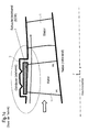
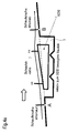
- the 1a schematically shows a portion of a fluid flow machine, consisting of a rotor blade row and a stator blade row. Particularly emphasized is the shroud arrangement at the outer blade end of the rotor. According to the prior art, the shroud arrangement consists of a large cavity, which is provided in the housing and completely absorbs the shroud to create a smooth as possible outer main flow path boundary.
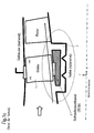
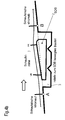
- the 1b shows schematically shows a portion of a fluid flow machine, consisting of a fixed stator blade row and a rotor blade row. Particularly emphasized is the shroud arrangement at the inner blade end of the fixed stator. According to the prior art, the shroud arrangement from a large cavity provided in the hub, which completely accommodates the shroud to provide the smoothest possible internal main flow path boundary.
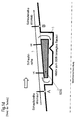
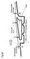
- the Figure 1C schematically shows a portion of a fluid flow machine, consisting of a series of adjustable (variable) stators and a rotor blade row. Particularly emphasized is the shroud arrangement on the inner blade end of the adjusting stator. According to the prior art, the shroud arrangement here also consists of a large cavity, which is provided in the hub and which completely absorbs the shroud in order to create the smoothest possible inner main flow path boundary.
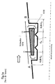
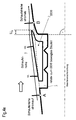
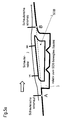
- the Fig.1d shows, representative of shrouds of adjustable or fixed rotors and stators, an arrangement of three rows of blades at the edge of the main flow path of a fluid flow machine, consisting of an upstream row of blades, a row of blades with shroud and a downstream row of blades.
- This representation may be both a region on the housing and a region on the hub of the fluid flow machine.
- the shroud is embedded in a surrounding component or a surrounding assembly (rotor hub or housing) and fits smoothly in the course of the main flow path according to the prior art without any projection.
- the shroud may be solid or (not shown here) hollow and consists of one or more components.
- the leakage flow occurring between the shroud and the surrounding component (small arrows), which runs counter to the main flow direction (thick arrow), is reduced by a number of sealing tips.
- the sealing tips can be arranged on the surrounding component or also (as not shown here) on the shroud itself be. There is usually a relative movement between the surrounding component and the shroud. In the area of the shroud, the leading edge (VK) and trailing edge (HK) of the considered blade row are indicated.
- the trailing edge of the upstream blade row is indicated; the base of this HK is marked with A.
- the leading edge of the upstream blade row is indicated; the base of this VK is marked B.
- a thin long arrow characterizes the near-edge flow along the substantially smooth boundary of the main flow path. According to the prior art, the shroud does not protrude beyond the connecting line between A and B in the main flow path. A very slight supernatant, but measured against other dimensions of the shroud subordinate small, can occur in the prior art due to manufacturing tolerances or come to operating points of the fluid flow machine off the design state by thermal detuning of the components.
- Fig.1d sketched enters the flow in the edge region of the main flow path without influencing by a paragraph or unevenness in the contour in the blade row with shroud and runs smoothly over the arranged in alignment with the rest of the contour shroud away.
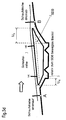
- the position of the point A is determined by a distance from the leading edge of 25% of the axial length Cx at the edge of the shrouded blade row, see 1E ,
- the position of point B is determined by a distance to the trailing edge of 25% of the axial length Cx at the edge of the shrouded blade row, see 1E ,
- the invention has for its object to provide a fluid flow machine of the type mentioned, which avoids the disadvantages of the prior art and minimizes shroud leakage flows.
- the present invention includes designing a shroud of the blade row of a fluid power machine such that at least one location of the perimeter and at least one of the leading and trailing areas, the contour of the shroud extends beyond a straight line of the adjacent blade edges of adjacent blade rows such that in the region of one of the openings, with which the shroud cavity communicates with the main flow path, there is a curved course of the main flow path contour and the flow lines at the edge of the main flow path.
- a bucket cover assembly for use in a turbomachine, which is provided by a local projection in the region of the leading edge and / or the trailing edge additionally influences the course of the flow at the edge of the main flow path and in this way reduces the pressure gradient acting on the cavity for the shroud leakage flow.
- a conventional prior art shroud configuration as shown in FIG Fig.1d is shown, provides an entry of the edge flow in the blade row with shroud before influenced by a paragraph or unevenness in the contour.
- the flow passes smoothly over the openings of the shroud cavity, the side facing the main flow path and arranged in alignment with the upstream and downstream contour side of the shroud away.
- the applied to the Kavticiansötechnisch static pressures that determine the leakage current are fixed in such an arrangement.
- Purpose of the present inventive solution is to influence the static pressure at the leading edge and the trailing edge of the shroud by special shape of the shroud in the area of the Schaufelvorder- and / or the blade trailing edge so that the static pressure gradient between the Openings of the cavity and thus the leakage current is reduced or ideally prevented.
- Inventive shroud configurations are in Fig.3a to Fig.5d shown.
- Decisive for the present invention is solely the contour shaping of the shroud in the vicinity of the main flow path.
- the subject of the invention is the shape of the shroud in the deeper interior of the cavity in which the shroud is embedded.
- the subject of the invention is the exact design of the components surrounding the cavity and the design of the sealing tips.
- the aforementioned non-inventive features are outlined here for the sake of clarity only in so far simplified form, as is necessary for the representation and understanding of relevant relationships of the invention.
- FIG.3c show by way of example some shroud configurations according to the invention with a projection in the region of the front edge of the relevant blade row.
- a supernatant according to the invention is characterized in that in at least one freely selectable longitudinal section of the turbomachine, a portion of the shroud protrudes beyond the connecting line AB into the main flow path and in this way represents a perceptible resistance to the approaching flow.
- FIG. 3a shows a solution according to the invention, in which the projecting leading edge of the shroud is provided for better flow guidance with a rounding that can end upstream or downstream of the blade leading edge.
- 3b shows a solution according to the invention, in which the protruding leading edge of the shroud is provided for stagnation and better flow guidance with a nose whose Rounding on the main flow path side facing upstream or may end downstream of the blade leading edge.
- 3 c shows a solution according to the invention, in which the protruding leading edge of the shroud is provided for stagnation and better flow guidance with an overlap Ux.
- the overlap is characterized in that the upstream direction limiting wall of the cavity is not completely radially and rectilinearly, but at least locally obliquely upstream oriented so that a likewise oblique design of the shroud on the mainstream side facing away from the formation of a tilted against the radial direction and optionally curved channel between the shroud and the surrounding component results.
- the 4a to 4e show by way of example some shroud configurations according to the invention with a projection in the region of the trailing edge of the relevant blade row.
- a supernatant according to the invention is characterized in that in at least one freely selectable longitudinal section of the turbomachine, a portion of the shroud protrudes beyond the connecting line AB into the main flow path and in this way represents a return of the flow-limiting contour.
- FIG. 4a shows a solution according to the invention, in which the trailing edge of the shroud is designed substantially truncated.
- FIG. 4b shows a solution according to the invention, in which the trailing edge of the shroud is provided for better flow guidance with a rounding that can end downstream or upstream of the blade trailing edge.
- FIG. 4c shows a solution according to the invention, in which the trailing edge of the shroud is designed substantially sharp-edged.
- Fig.4d shows a solution according to the invention, in which the trailing edge of the shroud is provided for better flow guidance with a nose whose rounding can end on the main flow path side facing downstream or upstream of the blade trailing edge.
- FIG.4E shows a solution according to the invention, in which the trailing edge of the shroud is provided with an overlap Ux.
- the overlap is characterized in that the downstream end wall of the cavity is not completely radially and rectilinearly, but at least locally obliquely oriented downstream, so that a likewise oblique design of the shroud on the mainstream side facing away from the formation of a tilted against the radial direction and optionally curved channel between the shroud and the surrounding component results.
- Fig.5a to Fig.5d show by way of example some shroud configurations according to the invention with a projection in the region of the leading edge and in the region of the trailing edge of the relevant blade row.
- An inventive supernatant is characterized in that in at least one freely selectable longitudinal section of the fluid flow machine is a proportion of the shroud over the connecting line AB also in the main flow path.
- FIG. 5a shows a solution according to the invention, in which the projecting leading edge of the shroud is provided for better flow guidance with a rounding, wherein the trailing edge of the shroud is designed nose-shaped, and in which the Main flow path facing contour of the shroud within the blade row is substantially rectilinear.
- 5 b shows a solution according to the invention, in which the main flow path-facing contour of the shroud within the blade row is substantially concave.
- 5c shows a solution according to the invention, in which the main flow path-facing contour of the shroud within the blade row is substantially convex.
- 5d shows a solution according to the invention, in which the projecting leading edge of the shroud and also the projecting trailing edge of the shroud are designed for better flow guidance with overlap, and in which the main flow path-facing contour of the shroud within the blade row is substantially rectilinear.
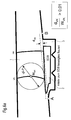
- the 6a shows a configuration with shroud overhang in the leading edge area.
- a tangent parallel to the connecting line AB at the position of maximum shroud protrusion defines the size of the shroud protrusion.
- the size of the maximum projection dVK is defined according to the invention relative to the annular channel width WVK at the front edge.
- the ring channel width WVK results as the diameter of a circle inscribed in the ring channel (main flow path) with the center MVK on the leading edge. According to the invention: dVK / WVK> 0.01.
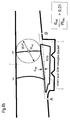
- the Figure 6b shows a configuration with shroud overhang in the trailing edge region.
- One parallel to the connecting line AB extending tangent to the location of maximum shroud protrusion defines the size of the shroud protrusion.
- the size of the maximum projection dHK is defined according to the invention relative to the annular channel width WHK at the trailing edge.
- the annular channel width WHK results as the diameter of a circle inscribed in the annular channel (main flow path) with the center MIC on the trailing edge. According to the invention: dHK / WHK> 0.01.
- the shroud protrusion in the leading edge region dVK is determined directly at the leading edge and the shroud projection in the trailing edge region dHK directly at the trailing edge.
- the Figure 7 defines favorable Axialerstreckened the shroud of the invention with supernatant. Due to the pressure field that arises due to the shroud overhang in the region of the shroud edges, it is particularly favorable to provide a comparatively long free section XVK of the shroud upstream of the blade leading edge. How out Fig. 7 it can be seen, this invention should be at least 7% of the axial extent of the blade row at the edge of the main flow path.
- this invention should be at least 7% of the axial extent of the blade row at the edge of the main flow path.
- the Figure 8 shows in a spatial view the leading edge region of a blade row with shroud over a portion of the circumference.
- the representation in FIG Figure 8 shows the inventive concept using the example of the leading edge region of a blade row with shroud, but the invention applies here also applies to a shroud overhang in the trailing edge region.
- the present invention allows a significantly higher aerodynamic load capacity of rotors and stators in turbomachines, with constant or increased efficiency.
- a reduction in specific fuel consumption of up to 0.5% is to be expected.
Abstract
Description
Die vorliegende Erfindung bezieht sich auf Schaufelreihen von Strömungsarbeitsmaschinen wie Bläser, Verdichter, Pumpen und Ventilatoren axialer oder halbaxialer Bauart mit gasförmigem oder flüssigem Arbeitsmedium. Die Strömungsarbeitsmaschine kann eine oder mehrere Stufen mit jeweils einem Rotor und einem Stator umfassen, in Einzelfällen wird die Stufe lediglich durch einen Rotor gebildet. Der Rotor besteht aus einer Anzahl von Schaufeln, die mit der rotierenden Welle der Maschine verbunden sind und Energie an das Arbeitsmedium abgeben. Der Rotor kann mit oder ohne Deckband am äußeren Schaufelende ausgeführt sein. Der Stator besteht aus einer Anzahl feststehender Schaufeln, die nabenseitig wie gehäuseseitig mit festem oder freiem Schaufelende ausgeführt sein können. Die Rotortrommel und die Beschaufelung sind üblicherweise von einem Gehäuse umgeben. Die Maschine kann auch einen Stator vor dem ersten Rotor, ein sogenanntes Vorleitrad aufweisen. Mindestens ein Stator oder Vorleitrad kann - abweichend von der unbeweglichen Fixierung - drehbar gelagert sein, um den Anstellwinkel zu verändern. Eine Verstellung erfolgt beispielsweise durch eine von außerhalb des Ringkanals zugängliche Spindel. Alternativ kann die besagte Strömungsarbeitsmaschine bei Mehrstufigkeit zwei gegenläufige Wellen besitzen, so dass die Rotorschaufelreihen von Stufe zu Stufe die Drehrichtung wechseln. Hierbei existieren keine Statoren zwischen aufeinander folgenden Rotoren. Schließlich kann die Strömungsarbeitsmaschine alternativ eine Nebenstromkonfiguration derart aufweisen, dass sich der einstromige Ringkanal hinter einer bestimmten Schaufelreihe in zwei konzentrische Ringkanäle aufteilt, die ihrerseits mindestens jeweils eine weitere Schaufelreihe beherbergen.
Die aerodynamische Belastbarkeit und die Effizienz von Strömungsarbeitsmaschinen, beispielsweise Bläsern, Verdichtern, Pumpen und Ventilatoren, wird durch das Wachstum und die Ablösung von Grenzschichten auf den Schaufeln sowie auf den Naben- und Gehäusewänden begrenzt. Der Stand der Technik hält für dieses fundamentale Problem nur bedingt Lösungen bereit. Eine Quelle der in Strömungsarbeitsmaschinen entstehenden Verluste besteht in der Leckageströmung um Schaufeldeckbänder, wie sie häufig am inneren Schaufelende von Statoren oder auch am äußeren Schaufelende von Rotoren zu finden sind. Die Leckageströmung wird üblicherweise durch Dichtspitzen, die innerhalb der Kavität, in die das Deckband eingebettet ist, angeordnet sind, klein gehalten. Die Leckageströmung kann dennoch, insbesondere in sehr hoch belasteten Schaufelreihen, die durch einen hohen statischen Druckanstieg und somit einen hohen Antrieb für die Leckageströmung gekennzeichnet sind, sehr schädliche Auswirkungen auf das Leistungsverhalten der Strömungsarbeitsmaschine haben.The aerodynamic load capacity and efficiency of fluid flow machines, such as fans, compressors, pumps and fans, is limited by the growth and separation of boundary layers on the blades and on the hub and casing walls. The state of the art provides only limited solutions to this fundamental problem. One source of losses in fluid power machines is leakage flow around blade shrouds, as often found at the inner blade end of stators or at the outer blade end of rotors. The leakage flow is usually kept small by sealing tips, which are arranged within the cavity in which the shroud is embedded. Nevertheless, the leakage flow can have very detrimental effects on the performance of the fluid flow machine, in particular in highly loaded blade rows, which are characterized by a high static pressure rise and thus a high drive for the leakage flow.
Die
Die
Die
Die
Das Deckband ist in ein umgebendes Bauteil oder eine umgebende Baugruppe (Rotornabe oder Gehäuse) eingebettet und fügt sich nach dem Stand der Technik ohne Überstand glatt in den Verlauf des Hauptströmungspfades ein. Das Deckband kann massiv oder auch (wie hier nicht gezeigt) hohl gestaltet sein und besteht aus einem oder mehreren Bauteilen. Die zwischen dem Deckband und dem umgebenden Bauteil auftretende Leckageströmung (kleine Pfeile), die entgegen der Hauptströmungsrichtung (dicker Pfeil) verläuft, wird durch eine Anzahl von Dichtspitzen gemindert. Die Dichtspitzen können am umgebenden Bauteil oder auch (wie hier nicht dargestellt) am Deckband selbst angeordnet sein. Zwischen dem umgebenden Bauteil und dem Deckband besteht üblicherweise eine Relativbewegung. Im Bereich des Deckbandes sind die Vorderkante (VK) und Hinterkante (HK) der betrachteten Schaufelreihe angedeutet. Stromauf des Deckbandes ist die Hinterkante der stromauf liegenden Schaufelreihe angedeutet; der Fußpunkt dieser HK ist mit A gekennzeichnet. Stromab des Deckbandes ist die Vorderkante der stromauf liegenden Schaufelreihe angedeutet; der Fußpunkt dieser VK ist mit B gekennzeichnet. Ein dünner langer Pfeil charakterisiert die randnahe Strömung entlang der im Wesentlichen glatt verlaufenden Berandung des Hauptströmungspfades. Dem Stand der Technik entsprechend ragt das Deckband nicht über die Verbindungslinie zwischen A und B hinaus in den Hauptströmungspfad. Ein sehr geringfügiger Überstand, der aber gemessen gegen andere Abmessungen des Deckbandes untergeordnet klein ist, kann beim Stand der Technik aufgrund von Fertigungstoleranzen auftreten oder auch an Betriebspunkten der Strömungsarbeitsmaschine abseits des Auslegungszustandes durch thermische Verstimmung der Bauteile zustande kommen. Wie in
Für den Fall, dass es stromauf des Deckbandes keine Schaufelreihe gibt, ist die Lage des Punktes A durch einen Abstand zur Vorderkante von 25% der axialen Länge Cx am Rand der mit Deckband versehenen Schaufelreihe bestimmt, siehe
Für den Fall, dass es stromab des Deckbandes keine Schaufelreihe gibt, ist die Lage des Punktes B durch einen Abstand zur Hinterkante von 25% der axialen Länge Cx am Rand der mit Deckband versehenen Schaufelreihe bestimmt, siehe
Bei Deckbandanordnungen nach dem Stand der Technik ist der Leckagestrom im Wesentlichen durch den Spalt gegeben, den die Dichtspitzen mit der gegenüberliegenden Kontur bilden. Dabei steigt der Leckagestrom mit der aerodynamischen Belastung, die für die mit Deckband versehene Schaufelreihe gewählt wird, stark an. Die Folge sind schlechte Betriebskennwerte im Hinblick auf den Wirkungsgrad, die Stabilität und die Weite des Betriebsbereichs der Strömungsarbeitsmaschine.In the case of shroud arrangements according to the prior art, the leakage flow is essentially given by the gap which the sealing tips form with the opposite contour. The leakage current with the aerodynamic load chosen for the shrouded blade row increases sharply. The result is poor operating characteristics with regard to the efficiency, stability and width of the operating range of the fluid power machine.
Der Erfindung liegt die Aufgabe zugrunde, eine Strömungsarbeitsmaschine der eingangs genannten Art zu schaffen, welche die Nachteile des Standes der Technik vermeidet und Deckband-Leckageströmungen minimiert.The invention has for its object to provide a fluid flow machine of the type mentioned, which avoids the disadvantages of the prior art and minimizes shroud leakage flows.
Erfindungsgemäß wird die Aufgabe durch die Merkmalskombination des Hauptanspruchs gelöst, die Unteransprüche zeigen weitere vorteilhafte Ausgestaltungen der Erfindung.According to the invention the object is achieved by the feature combination of the main claim, the subclaims show further advantageous embodiments of the invention.
Im Einzelnen umfasst die vorliegende Erfindung die Gestaltung eines Deckbandes der Schaufelreihe einer Strömungsarbeitsmaschine, derart, dass an wenigstens einem Ort des Umfangs und wenigstens in einem der Bereiche der Vorder- oder Hinterkante die Kontur des Deckbandes über eine geradlinige Verbindung der nächst gelegenen Schaufelkantenfußpunkte umliegender Schaufelreihen hinaus steht, derart, dass im Bereich einer der Öffnungen, mit denen die Deckbandkavität mit dem Hauptströmungspfad in Verbindung steht, ein geschwungener Verlauf der Hauptströmungspfadkontur und der Stromlinien am Rand des Hauptströmungspfades vorliegt.Specifically, the present invention includes designing a shroud of the blade row of a fluid power machine such that at least one location of the perimeter and at least one of the leading and trailing areas, the contour of the shroud extends beyond a straight line of the adjacent blade edges of adjacent blade rows such that in the region of one of the openings, with which the shroud cavity communicates with the main flow path, there is a curved course of the main flow path contour and the flow lines at the edge of the main flow path.
Erfindungsgemäß ist für den Einsatz in einer Strömungsarbeitsmaschine eine Schaufeldeckbandanordnung geschaffen, die durch einen lokalen Überstand im Bereich der Vorderkante und/oder der Hinterkante den Verlauf der Strömung am Rand des Hauptströmungspfades zusätzlich beeinflusst und auf diese Weise das für die Deckband-Leckageströmung bestimmende, an der Kavität wirkende Druckbefälle verringert.According to the invention, a bucket cover assembly is provided for use in a turbomachine, which is provided by a local projection in the region of the leading edge and / or the trailing edge additionally influences the course of the flow at the edge of the main flow path and in this way reduces the pressure gradient acting on the cavity for the shroud leakage flow.
Im Folgenden wird die Erfindung anhand von Ausführungsbeispielen in Verbindung mit den Figuren beschrieben. Dabei zeigt:
- Fig. 1a
- Schaufel nach dem Stand der Technik, Rotor
- Fig. 1b
- Schaufel nach dem Stand der Technik, fester Stator
- Fig. 1c
- Schaufel nach dem Stand der Technik, Verstell-Stator
- Fig. 1d
- Schaufeldeckbandkonfiguration, Stand der Technik, mit umliegenden Schaufelreihen
- Fig. 1e
- Schaufeldeckbandkonfiguration, Stand der Technik, ohne umliegende Schaufelreihen
- Fig. 2
- mögliche Konfigurationen erfindungsrelevanter Strömungsarbeitsmaschinen
- Fig. 3a
- Erfindungsgemäße Deckbandkonfiguration, Überstand im Vorderkantenbereich
- Fig. 3b
- Erfindungsgemäße Deckbandkonfiguration, Überstand mit Nase im Vorderkantenbereich
- Fig. 3c
- Erfindungsgemäße Deckbandkonfiguration, Überstand und Überlappung im Vorderkantenbereich
- Fig. 4a
- Erfindungsgemäße Deckbandkonfiguration, Überstand im Hinterkantenbereich, stumpfkantig
- Fig. 4b
- Erfindungsgemäße Deckbandkonfiguration, Überstand im Hinterkantenbereich, abgerundet
- Fig. 4c
- Erfindungsgemäße Deckbandkonfiguration, Überstand mit Spitze im Hinterkantenbereich
- Fig. 4d
- Erfindungsgemäße Deckbandkonfiguration, Überstand mit Nase im Hinterkantenbereich
- Fig. 4e
- Erfindungsgemäße Deckbandkonfiguration, Überstand und Überdeckung im Hinterkantenbereich
- Fig. 5a
- Erfindungsgemäße Deckbandkonfiguration, Überstand im Vorder- und Hinterkantenbereich, geradlinige Kontur innerhalb der Schaufelreihe
- Fig. 5b
- Erfindungsgemäße Deckbandkonfiguration, Überstand im Vorder- und Hinterkantenbereich, konvexe Kontur innerhalb der Schaufelreihe
- Fig. 5c
- Erfindungsgemäße Deckbandkonfiguration, Überstand im Vorder- und Hinterkantenbereich, konkave Kontur innerhalb der Schaufelreihe
- Fig. 5d
- Erfindungsgemäße Deckbandkonfiguration, Überstand und Überlappung im Vorder- und Hinterkantenbereich
- Fig. 6a
- Größe des Überstandes im Vorderkantenbereich
- Fig. 6b
- Größe des Überstandes im Hinterkantenbereich
- Fig. 7
- Erfindungsgemäße Axialersteckungen des Deckbandes
- Fig. 8
- Periodische Umfangsvariation des Überstandes im Vorderkantenbereich, räumliche Ansicht
- Fig. 1a
- Blade according to the prior art, rotor
- Fig. 1b
- Blade according to the prior art, fixed stator
- Fig. 1c
- Blade according to the prior art, adjustable stator
- Fig. 1d
- Bucket deck configuration, prior art, with surrounding rows of blades
- Fig. 1e
- Bucket deck configuration, prior art, without surrounding rows of blades
- Fig. 2
- possible configurations of inventive flow machines
- Fig. 3a
- Inventive shroud configuration, protrusion in the leading edge area
- Fig. 3b
- Inventive shroud configuration, projection with nose in the leading edge area
- Fig. 3c
- Inventive shroud configuration, overhang and overlap in the leading edge area
- Fig. 4a
- Inventive shroud configuration, protrusion in the trailing edge region, butt-edged
- Fig. 4b
- Inventive shroud configuration, projection in the trailing edge region, rounded
- Fig. 4c
- Inventive shroud configuration, protrusion with a peak in the trailing edge region
- Fig. 4d
- Inventive shroud configuration, projection with nose in the trailing edge region
- Fig. 4e
- Inventive shroud configuration, overhang and overlap in the trailing edge region
- Fig. 5a
- Inventive shroud configuration, protrusion in the leading and trailing edge region, rectilinear contour within the blade row
- Fig. 5b
- Inventive shroud configuration, protrusion in the leading and trailing edge region, convex contour within the blade row
- Fig. 5c
- Inventive shroud configuration, protrusion in the leading and trailing edge region, concave contour within the blade row
- Fig. 5d
- Inventive shroud configuration, projection and overlap in the leading and trailing edge region
- Fig. 6a
- Size of the supernatant in the leading edge area
- Fig. 6b
- Size of the supernatant in the trailing edge area
- Fig. 7
- Inventive Axialersteckungen the shroud
- Fig. 8
- Periodic circumferential variation of the supernatant in the leading edge area, spatial view
Eine konventionelle Deckbandkonfiguration nach dem Stand der Technik, wie sie in
Zweck der vorliegenden erfindungsgemäßen Lösung ist es, den statischen Druck an der Anströmkante und der Abströmkante des Deckbandes durch besondere Gestalt des Deckbandes im Bereich der Schaufelvorder- und /oder der Schaufelhinterkante so zu beeinflussen, dass das statische Druckgefälle zwischen den Öffnungen der Kavität und damit der Leckagestrom verringert oder idealerweise unterbunden wird.Purpose of the present inventive solution is to influence the static pressure at the leading edge and the trailing edge of the shroud by special shape of the shroud in the area of the Schaufelvorder- and / or the blade trailing edge so that the static pressure gradient between the Openings of the cavity and thus the leakage current is reduced or ideally prevented.
Erfindungsgemäße Deckbandkonfigurationen sind in
Die
Die
Die
Die
Die
Die
Befindet sich der maximal gefundene Überstand innerhalb der Schaufelreihe zwischen Vorder- und Hinterkante, wird der Deckbandüberstand im Vorderkantenbereich dVK direkt an der Vorderkante und der Deckbandüberstand im Hinterkantenbereich dHK direkt an der Hinterkante ermittelt.If the maximum supernatant found within the blade row is between the leading and trailing edges, the shroud protrusion in the leading edge region dVK is determined directly at the leading edge and the shroud projection in the trailing edge region dHK directly at the trailing edge.
Die
Aus gleichen Gründen ist es günstig, einen vergleichsweise langen freien Abschnitt XHK des Deckbandes stromab der Schaufelhinterkante vorzusehen. Wie aus
Die
Weitere Beschreibung der Erfindung:
- 1. Deckband einer Schaufelreihe von verdrehbaren oder unverdrehbar fixierten Stator- oder Rotorschaufeln für die Verwendung in einer Strömungsarbeitsmaschine, insbesondere in einem Flugtriebwerkverdichter, mit besonderer Gestaltung zur Reduzierung auftretender Leckageströme, wobei
- a.) das Deckband, betrachtet in einem Längsschnitt der Strömungsarbeitsmaschine, unter Ausbildung einer mit dem Hauptströmungspfad in Verbindung stehenden Kavität (Ausnehmung) wenigstens teilweise in ein Bauteil oder eine Bauteilgruppe, rotierende Welle oder stehendes Gehäuse, eingebettet ist
- b.) das Deckband, in Maschinenachsrichtung betrachtet, zwischen zwei am Rand des Hauptströmungspfades der Strömungsarbeitsmaschine befindlichen Referenzpunkten A und B angeordnet ist
- c.) der Referenzpunkt A durch den Fußpunkt der Hinterkante der stromauf des Deckbandes befindlichen Schaufelreihe beziehungsweise bei Fehlen dieser Schaufelreihe durch einen Randpunkt des Hauptströmungspfades gebildet wird, der sich 25% der axialen Erstreckung der mit Deckband versehenen Schaufelreihe stromauf der Vorderkante der mit Deckband versehenen Schaufelreihe befindet
- d.) der Referenzpunkt B durch den Fußpunkt der Vorderkante der stromab des Deckbandes befindlichen Schaufelreihe beziehungsweise bei Fehlen dieser Schaufelreihe durch einen Randpunkt des Hauptströmungspfades gebildet wird, der sich 25% der axialen Erstreckung der mit Deckband versehenen Schaufelreihe stromab der Hinterkante der mit Deckband versehenen Schaufelreihe befindet
- e.) das Deckband an wenigstens einem Ort des Umfangs und in wenigstens einem der Bereiche der Vorder- oder Hinterkante der zugehörigen Schaufelreihe über eine geradlinige Verbindung der Referenzpunkte A und B hinaus in den Hauptströmungspfad steht, derart, dass aufgrund dieses Deckbandüberstandes im Bereich wenigstens einer der Öffnungen, über die der Hauptströmungspfad mit der Kavität um das Deckband in Verbindung steht, ein geschwungener Verlauf der effektiven Hauptströmungspfadbegrenzung sowie der Stromlinien am Rand des Hauptströmungspfades erreicht wird.
- 2.
Deckband nach Punkt 1, wobei die überstehende Anströmkante des Deckbandes zur besseren Strömungsführung mit einer Abrundung versehen ist, die stromauf oder auch stromab der Schaufelvorderkante endet. - 3.
Deckband nach Punkt 1oder 2, wobei die überstehende Anströmkante des Deckbandes zur Staupunktbildung und zur besseren Strömungsführung mit einer Nase versehen ist, deren Rundung auf der hauptströmungspfadzugewandten Seite stromauf oder auch stromab der Schaufelvorderkante endet. - 4. Deckband nach einem der Punkte 1
bis 3, wobei die überstehende Anströmkante des Deckbandes zur Staupunktbildung und zur besseren Strömungsführung eine Überlappung aufweist, derart, dass die in Hauptströmungsrichtung betrachtet vordere begrenzende Wandung der Kavität nicht in radialer Richtung, sondern wenigstens örtlich schräg stromauf orientiert ist, und auf diese Weise durch die schräge Gestaltung der Rückseite des Deckbandes in diesem Bereich ein gegen die radiale Richtung geneigter und gegebenenfalls gekrümmter Kanal zwischen dem Deckband und dem umgebenden Bauteil ausgebildet ist. - 5. Deckband nach einem der Punkte 1 bis 4, wobei die überstehende Abströmkante des Deckbandes im Wesentlichen stumpfkantig ausgeführt ist.
- 6. Deckband nach einem der Punkte 1 bis 5, wobei die überstehende Abströmkante des Deckbandes zur besseren Strömungsführung mit einer Abrundung versehen ist, die stromab oder auch stromauf der Schaufelhinterkante endet.
- 7. Deckband nach einem der Punkte 1 bis 6, wobei die überstehende Abströmkante des Deckbandes im Wesentlichen scharfkantig ausgeführt ist.
- 8. Deckband nach einem der Punkte 1 bis 7, wobei die überstehende Abströmkante des Deckbandes zur besseren Strömungsführung mit einer Nase versehen ist, deren Rundung auf der hauptströmungspfadzugewandten Seite stromab oder auch stromauf der Schaufelhinterkante endet.
- 9. Deckband nach einem der Punkte 1 bis 8, wobei die Abströmkante des Deckbandes zur besseren Strömungsführung eine Überlappung aufweist, derart, dass die in Hauptströmungsrichtung betrachtet hintere begrenzende Wandung der Kavität nicht in radialer Richtung, sondern wenigstens örtlich schräg stromab orientiert ist, und auf diese Weise durch die schräge Gestaltung der Rückseite des Deckbandes in diesem Bereich ein gegen die radiale Richtung geneigter und gegebenenfalls gekrümmter Kanal zwischen dem Deckband und dem umgebenden Bauteil ausgebildet ist.
- 10. Deckband nach einem der einem der Punkte 1 bis 9, wobei sowohl ein Deckbandüberstand im Vorderkantenbereich als auch ein Deckbandüberstand im Hinterkantenbereich vorgesehen sind.
- 11. Deckband nach Punkt 10, wobei die hauptströmungspfadzugewandte Kontur des Deckbandes in wenigstens einem Teilabschnitt zwischen Anström- und Abströmkante des Deckbandes im Wesentlichen geradlinig verläuft.
- 12. Deckband nach Punkt 10, wobei die hauptströmungspfadzugewandte Kontur des Deckbandes in wenigstens einem Teilabschnitt zwischen Anström- und Abströmkante des Deckbandes im Wesentlichen konkav verläuft.
- 13. Deckband nach Punkt 10, wobei die hauptströmungspfadzugewandte Kontur des Deckbandes in wenigstens einem Teilabschnitt zwischen Anström- und Abströmkante des Deckbandes im Wesentlichen konvex verläuft.
- 14. Deckband nach Punkt 10, wobei die überstehende Anströmkante des Deckbandes und ebenfalls die überstehende Abströmkante des Deckbandes mit Überlappung ausgeführt sind und die Überlappungen so ausgestaltet sind, dass eine im Wesentlichen V-förmige Kavität um das Deckband vorliegt.
- 15. Deckband nach einem der Punkte 1 bis 14, wobei ein vorgesehener Deckbandüberstand sowie die Form der betroffenen Kante des Deckbandes periodisch in Umfangsrichtung der Schaufelreihe, zu der das Deckband gehört, variiert.
- 16. Deckband nach Punkt 15, wobei die Periode P der umfangsgerichteten Variation des Deckbandüberstandes und der Deckbandkantenform in einem ganzzahligen Verhältnis zur Schaufelteilung S der mit Deckband versehenen Schaufelreihe steht: n x P = S.
- 17. Deckband nach einem der Punkte 1 bis 16, wobei der Deckbandüberstand d, definiert als Abstand zwischen der Referenzlinie A-B und einer parallel dazu verlaufende Tangente an die Stelle des maximalen Deckbandüberstandes und bezogen auf die Ringkanalweite W an der dem Ort des maximalen Überstandes nächst gelegenen Schaufelkante (VK oder HK)
mehr als 1% beträgt (dVK / WVK > 0,01 beziehungsweise dHK / WHK > 0,01), wobei einschränkend gilt, dass der Deckbandüberstand im Vorderkantenbereich dVK direkt an der Schaufelvorderkante und der Deckbandüberstand im Hinterkantenbereich dHK direkt an der Schaufelhinterkante zu ermitteln ist, wenn sich der Ort des maximalen Deckbandüberstandes innerhalb der Schaufelreihe zwischen Vorder- und Hinterkante befindet. - 18. Deckband nach einem der Punkte 1 bis 17, wobei ein freier Abschnitt XVK des Deckbandes stromauf der Schaufelvorderkante vorgesehen ist, dessen Länge bezogen auf die axiale Erstreckung der Schaufelreihe am Rand des Hauptströmungspfades (VK zu HK) mindestens 7% beträgt.
- 19. Deckband nach einem der Punkte 1 bis 17, wobei ein freier Abschnitt XHK des Deckbandes stromab der Schaufelhinterkante vorgesehen ist, dessen Länge bezogen auf die axiale Erstreckung der Schaufelreihe am Rand des Hauptströmungspfades (VK zu HK) mindestens 7% beträgt.
- 1. shroud of a blade row of rotatable or non-rotatably fixed stator or rotor blades for use in a fluid flow machine, in particular in an aircraft engine compressor, with special design for reducing occurring leakage currents, wherein
- a.) the shroud, viewed in a longitudinal section of the fluid flow machine, at least partially embedded in a component or a group of components, rotating shaft or stationary housing, forming a communicating with the main flow path cavity (recess)
- b.) the shroud, viewed in the machine axis direction, between two located at the edge of the main flow path of the fluid flow machine reference points A and B is arranged
- c.) the reference point A is formed by the root of the trailing edge of the blade row upstream of the shroud or, in the absence of this blade row, by an edge point of the main flow path which is 25% of the axial extent of the shrouded blade row upstream of the leading edge of the shrouded blade row is
- d.) the reference point B is formed by the root of the leading edge of the blade row downstream of the shroud, or in the absence of this blade row by an edge point of the main flow path which is 25% of the axial extent of the shrouded blade row downstream of the trailing edge of the shrouded blade row is
- e.) the shroud is in at least one location of the circumference and in at least one of the areas of the leading or trailing edge of the associated blade row over a straight line connection of the reference points A and B in the main flow path, such that due to this shroud overhang in the area at least one the openings through which the main flow path communicates with the cavity around the shroud, a curved course of the effective main flow path boundary and the flow lines at the edge of the main flow path is achieved.
- 2. shroud according to
item 1, wherein the protruding leading edge of the shroud is provided for better flow guidance with a rounding, which ends upstream or downstream of the blade leading edge. - 3. shroud according to
item - 4. shroud according to one of the
items 1 to 3, wherein the protruding leading edge of the shroud for stagnation and better flow guidance has an overlap, such that the main flow direction viewed in the front limiting wall of the cavity not oriented radially, but at least locally obliquely upstream is, and is formed in this way by the oblique design of the back of the shroud in this area an inclined against the radial direction and optionally curved channel between the shroud and the surrounding component. - 5. shroud according to one of the
items 1 to 4, wherein the projecting trailing edge of the shroud is designed substantially truncated. - 6. shroud according to one of the
items 1 to 5, wherein the projecting trailing edge of the shroud is provided for better flow guidance with a rounding, which ends downstream or upstream of the blade trailing edge. - 7. shroud according to one of the
items 1 to 6, wherein the projecting trailing edge of the shroud is substantially sharp-edged. - 8. shroud according to one of the
items 1 to 7, wherein the projecting trailing edge of the shroud for better flow guidance is provided with a nose whose rounding on the mainstream path side downstream or upstream of the blade trailing edge ends. - 9. shroud according to one of the
items 1 to 8, wherein the trailing edge of the shroud for better flow guidance has an overlap, such that the main flow direction viewed in the rear limiting wall of the cavity is not oriented radially in the radial direction, but at least locally downstream, and on this manner is formed by the oblique design of the back of the shroud in this area an inclined against the radial direction and optionally curved channel between the shroud and the surrounding component. - 10. shroud according to one of the one of the
items 1 to 9, wherein both a shroud projection in the leading edge region and a shroud projection in the trailing edge region are provided. - 11. shroud according to item 10, wherein the main flow path-facing contour of the shroud in at least one section between the inflow and outflow edge of the shroud is substantially rectilinear.
- 12. shroud according to item 10, wherein the main flow path-facing contour of the shroud in at least one section between the inflow and outflow edge of the shroud is substantially concave.
- 13. shroud according to item 10, wherein the main flow path-facing contour of the shroud in at least one section between the inflow and outflow edge of the shroud is substantially convex.
- 14. shroud according to item 10, wherein the projecting leading edge of the shroud and also the projecting trailing edge of the shroud are designed with overlap and the overlaps are designed so that a substantially V-shaped cavity is present around the shroud.
- 15. shroud according to any one of
items 1 to 14, wherein an intended shroud projection and the shape of the affected edge of the shroud periodically in the circumferential direction of the blade row to which the shroud belongs varies. - 16. The shroud according to item 15, wherein the period P of the circumferential variation of the shroud projection and the shroud edge form is in an integer ratio to the blade pitch S of the shrouded blade row: nx P = S.
- 17 shroud according to one of the
items 1 to 16, wherein the shroud projection d, defined as the distance between the reference line AB and a parallel tangent to the position of the maximum shroud overhang and based on the annular channel width W at the location of the maximum supernatant nearest Blade edge (VK or HK) is more than 1% (dVK / WVK> 0.01 or dHK / WHK> 0.01), wherein restricting is that the shroud overhang in the leading edge region dVK directly to the blade leading edge and the shroud overhang in the trailing edge region dHK directly at the trailing edge of the blade, when the location of the maximum shroud protrusion is within the blade row between the leading and trailing edges. - 18. shroud according to one of the
items 1 to 17, wherein a free portion XVK of the shroud upstream of the blade leading edge is provided, whose length relative to the axial extent of the blade row at the edge of the main flow path (VK to HK) is at least 7%. - 19. The shroud according to any one of
items 1 to 17, wherein a free portion XHK of the shroud is provided downstream of the blade trailing edge, whose length relative to the axial extent of the blade row at the edge of the main flow path (VK to HK) is at least 7%.
Die vorliegende Erfindung erlaubt eine deutlich höhere aerodynamische Belastbarkeit von Rotoren und Statoren in Strömungsarbeitmaschinen, bei gleich bleibendem oder erhöhtem Wirkungsgrad. Bei Einsatz des Konzeptes im Hochdruckverdichter eines Flugtriebwerkes mit rund 25000 Pfund Schub ist eine Reduzierung des spezifischen Kraftstoffverbrauches von bis zu 0,5% zu erwarten.The present invention allows a significantly higher aerodynamic load capacity of rotors and stators in turbomachines, with constant or increased efficiency. When using the concept in the high-pressure compressor of an aircraft engine with about 25,000 pounds of thrust, a reduction in specific fuel consumption of up to 0.5% is to be expected.
Claims (19)
dadurch gekennzeichnet,
characterized,
wobei der Deckbandüberstand im Vorderkantenbereich dVK direkt an der Schaufelvorderkante und der Deckbandüberstand im Hinterkantenbereich dHK direkt an der Schaufelhinterkante definiert ist, wenn sich der Ort des maximalen Deckbandüberstandes innerhalb der Schaufelreihe zwischen Vorderkante und Hinterkante befindet.Turbomachine according to one of claims 1 to 16, characterized in that the shroud projection d, defined as the distance between the reference line AB and a parallel tangent to the position of the maximum shroud overhang and based on the annular channel width W at the location of the maximum supernatant nearest Blade edge (front edge (VK) or trailing edge (HK)) is more than 1% and thus satisfies the following equations:
wherein the shroud protrusion in the leading edge region dVK directly at the blade leading edge and the shroud protrusion in the trailing edge region dHK directly at the blade trailing edge is defined when the location of the maximum shroud protrusion is within the blade row between the leading edge and the trailing edge.
Applications Claiming Priority (1)
| Application Number | Priority Date | Filing Date | Title |
|---|---|---|---|
| DE102007027427A DE102007027427A1 (en) | 2007-06-14 | 2007-06-14 | Bucket cover tape with overhang |
Publications (3)
| Publication Number | Publication Date |
|---|---|
| EP2003292A2 true EP2003292A2 (en) | 2008-12-17 |
| EP2003292A3 EP2003292A3 (en) | 2012-04-04 |
| EP2003292B1 EP2003292B1 (en) | 2019-12-18 |
Family
ID=39739925
Family Applications (1)
| Application Number | Title | Priority Date | Filing Date |
|---|---|---|---|
| EP08010395.5A Active EP2003292B1 (en) | 2007-06-14 | 2008-06-06 | Fluid working machine having blade shroud with overhang |
Country Status (3)
| Country | Link |
|---|---|
| US (1) | US8202044B2 (en) |
| EP (1) | EP2003292B1 (en) |
| DE (1) | DE102007027427A1 (en) |
Cited By (4)
| Publication number | Priority date | Publication date | Assignee | Title |
|---|---|---|---|---|
| EP2607625A1 (en) * | 2011-12-20 | 2013-06-26 | MTU Aero Engines GmbH | Turbomachine and stage of turbomachine |
| KR20130131452A (en) * | 2011-03-30 | 2013-12-03 | 미츠비시 쥬고교 가부시키가이샤 | Gas turbine |
| EP2806103A1 (en) * | 2013-05-24 | 2014-11-26 | MTU Aero Engines GmbH | Cascade, blades and flow engine |
| EP2617942A4 (en) * | 2010-09-17 | 2018-02-28 | Mitsubishi Hitachi Power Systems, Ltd. | Turbine |
Families Citing this family (14)
| Publication number | Priority date | Publication date | Assignee | Title |
|---|---|---|---|---|
| GB0901473D0 (en) * | 2009-01-30 | 2009-03-11 | Rolls Royce Plc | An axial-flow turbo machine |
| EP2462412A4 (en) * | 2009-08-06 | 2014-01-22 | Airbus Engineering Ct India | System and method for computing an equi-distance point (edp) for aircrafts |
| US8714908B2 (en) * | 2010-11-05 | 2014-05-06 | General Electric Company | Shroud leakage cover |
| JP2012233406A (en) * | 2011-04-28 | 2012-11-29 | Hitachi Ltd | Gas turbine stator vane |
| US9885368B2 (en) | 2012-05-24 | 2018-02-06 | Carrier Corporation | Stall margin enhancement of axial fan with rotating shroud |
| US20140140822A1 (en) * | 2012-11-16 | 2014-05-22 | General Electric Company | Contoured Stator Shroud |
| WO2015119699A2 (en) * | 2013-12-05 | 2015-08-13 | United Technologies Corporation | Turbomachine rotor-stator seal |
| US10161250B2 (en) | 2015-02-10 | 2018-12-25 | United Technologies Corporation | Rotor with axial arm having protruding ramp |
| US9938840B2 (en) * | 2015-02-10 | 2018-04-10 | United Technologies Corporation | Stator vane with platform having sloped face |
| DE102015206384A1 (en) * | 2015-04-09 | 2016-10-13 | Rolls-Royce Deutschland Ltd & Co Kg | Shroud arrangement of a row of blades of stator or rotor blades |
| BE1025961B1 (en) * | 2018-01-30 | 2019-08-28 | Safran Aero Boosters S.A. | ANNULAR PASSAGE BETWEEN A VIROLE AND A ROTORIC PLATFORM OF TURBOMACHINE |
| JP7325213B2 (en) * | 2019-04-10 | 2023-08-14 | 三菱重工業株式会社 | Stator vane units and compressors and gas turbines |
| FR3106627B1 (en) | 2020-01-24 | 2023-03-17 | Safran Aircraft Engines | WAVE TIPPING AT ROTOR-STATOR AIR GAP IN A TURBOMACHINE COMPRESSOR |
| FR3106626B1 (en) * | 2020-01-24 | 2022-06-10 | Safran Aircraft Engines | DIFFERENTIATED SWITCHING BETWEEN ROTOR AND STATOR AT ROTOR-STATOR AIR GATES IN A TURBOMACHINE COMPRESSOR |
Family Cites Families (17)
| Publication number | Priority date | Publication date | Assignee | Title |
|---|---|---|---|---|
| CH112269A (en) * | 1923-12-22 | 1925-10-16 | Erste Bruenner Maschinen Fab | Blade device on axial steam or gas turbines. |
| US3065955A (en) * | 1958-12-29 | 1962-11-27 | Gen Electric | Rotor blade and shroud assembly |
| CH432554A (en) * | 1965-04-22 | 1967-03-31 | Escher Wyss Ag | Constant pressure turbine stage |
| US3640638A (en) * | 1969-07-02 | 1972-02-08 | Rolls Royce | Axial flow compressor |
| JPS5447907A (en) * | 1977-09-26 | 1979-04-16 | Hitachi Ltd | Blading structure for axial-flow fluid machine |
| US4844692A (en) * | 1988-08-12 | 1989-07-04 | Avco Corporation | Contoured step entry rotor casing |
| FR2666846B1 (en) * | 1990-09-13 | 1992-10-16 | Alsthom Gec | VANE GRILLE FOR TURBOMACHINE PROVIDED WITH SUCTION SLOTS IN THE CEILING AND / OR IN THE FLOOR AND TURBOMACHINE COMPRISING SUCH GRIDS. |
| EP0626036B1 (en) * | 1992-02-10 | 1996-10-09 | United Technologies Corporation | Improved cooling fluid ejector |
| US5488825A (en) * | 1994-10-31 | 1996-02-06 | Westinghouse Electric Corporation | Gas turbine vane with enhanced cooling |
| US5607284A (en) * | 1994-12-29 | 1997-03-04 | United Technologies Corporation | Baffled passage casing treatment for compressor blades |
| EP0799973B1 (en) * | 1996-04-01 | 2002-07-03 | Alstom | Wall contour for an axial turbomachine |
| JPH10184304A (en) * | 1996-12-27 | 1998-07-14 | Toshiba Corp | Turbine nozzle and turbine moving blade of axial flow turbine |
| JP3883245B2 (en) * | 1997-02-26 | 2007-02-21 | 株式会社東芝 | Axial flow turbine |
| US6511294B1 (en) * | 1999-09-23 | 2003-01-28 | General Electric Company | Reduced-stress compressor blisk flowpath |
| JP2002371802A (en) * | 2001-06-14 | 2002-12-26 | Mitsubishi Heavy Ind Ltd | Shroud integrated type moving blade in gas turbine and split ring |
| US7063509B2 (en) * | 2003-09-05 | 2006-06-20 | General Electric Company | Conical tip shroud fillet for a turbine bucket |
| JP2006138259A (en) * | 2004-11-12 | 2006-06-01 | Mitsubishi Heavy Ind Ltd | Axial flow turbine |
-
2007
- 2007-06-14 DE DE102007027427A patent/DE102007027427A1/en not_active Withdrawn
-
2008
- 2008-06-06 EP EP08010395.5A patent/EP2003292B1/en active Active
- 2008-06-12 US US12/155,950 patent/US8202044B2/en active Active
Non-Patent Citations (1)
| Title |
|---|
| None |
Cited By (7)
| Publication number | Priority date | Publication date | Assignee | Title |
|---|---|---|---|---|
| EP2617942A4 (en) * | 2010-09-17 | 2018-02-28 | Mitsubishi Hitachi Power Systems, Ltd. | Turbine |
| KR20130131452A (en) * | 2011-03-30 | 2013-12-03 | 미츠비시 쥬고교 가부시키가이샤 | Gas turbine |
| EP2692993A1 (en) * | 2011-03-30 | 2014-02-05 | Mitsubishi Heavy Industries, Ltd. | Gas turbine |
| EP2692993A4 (en) * | 2011-03-30 | 2014-08-27 | Mitsubishi Heavy Ind Ltd | Gas turbine |
| US9689272B2 (en) | 2011-03-30 | 2017-06-27 | Mitsubishi Heavy Industries, Ltd. | Gas turbine and outer shroud |
| EP2607625A1 (en) * | 2011-12-20 | 2013-06-26 | MTU Aero Engines GmbH | Turbomachine and stage of turbomachine |
| EP2806103A1 (en) * | 2013-05-24 | 2014-11-26 | MTU Aero Engines GmbH | Cascade, blades and flow engine |
Also Published As
| Publication number | Publication date |
|---|---|
| DE102007027427A1 (en) | 2008-12-18 |
| US8202044B2 (en) | 2012-06-19 |
| EP2003292B1 (en) | 2019-12-18 |
| EP2003292A3 (en) | 2012-04-04 |
| US20080310961A1 (en) | 2008-12-18 |
Similar Documents
| Publication | Publication Date | Title |
|---|---|---|
| EP2003292B1 (en) | Fluid working machine having blade shroud with overhang | |
| EP1632662B1 (en) | Turbomachine with bleeding | |
| EP2025945B1 (en) | Flow working machine with ring canal wall fitting | |
| EP2096316B1 (en) | Housing structuring for axial compressor in the hub area | |
| EP1657401B1 (en) | Turbomachine comprising blades with an extended profile chord length in its tip region | |
| EP2261463B1 (en) | Turbomachine with a group of bladed stages | |
| EP2194232B1 (en) | Turbo engine with side wall boundary layer barrier | |
| EP2761137B1 (en) | Blade of a row of rotor blades or stator blades for use in a turbomachine | |
| EP2275643B1 (en) | Engine blade with excess front edge loading | |
| EP2138727A2 (en) | Blade shrouds with outlet | |
| DE102008031982A1 (en) | Turbomachine with groove at a trough of a blade end | |
| EP3078804A1 (en) | Shroud assembly of a row of stator or rotor blades and corresponding turbine | |
| EP2025946A2 (en) | Rotor shroud with blocking stream production | |
| EP2947270B1 (en) | Rotor series group | |
| EP2180195A2 (en) | Turbo machine with tip clearance control | |
| EP1759090A1 (en) | Vane comprising a transition zone | |
| EP2846000B1 (en) | Vane ring of a gas turbine | |
| EP2913479B1 (en) | Tandem blades of a turbo-machine | |
| DE102013020826A1 (en) | Radial compressor stage | |
| EP1953340B1 (en) | Flow machine and rotor shovel for a flow machine | |
| DE10340827A1 (en) | Repair method for a blade of a fluid flow machine | |
| DE10352789B4 (en) | gas turbine | |
| EP3375977A1 (en) | Contouring of a platform in an airfoil cascade |
Legal Events
| Date | Code | Title | Description |
|---|---|---|---|
| PUAI | Public reference made under article 153(3) epc to a published international application that has entered the european phase |
Free format text: ORIGINAL CODE: 0009012 |
|
| AK | Designated contracting states |
Kind code of ref document: A2 Designated state(s): AT BE BG CH CY CZ DE DK EE ES FI FR GB GR HR HU IE IS IT LI LT LU LV MC MT NL NO PL PT RO SE SI SK TR |
|
| AX | Request for extension of the european patent |
Extension state: AL BA MK RS |
|
| PUAL | Search report despatched |
Free format text: ORIGINAL CODE: 0009013 |
|
| AK | Designated contracting states |
Kind code of ref document: A3 Designated state(s): AT BE BG CH CY CZ DE DK EE ES FI FR GB GR HR HU IE IS IT LI LT LU LV MC MT NL NO PL PT RO SE SI SK TR |
|
| AX | Request for extension of the european patent |
Extension state: AL BA MK RS |
|
| RIC1 | Information provided on ipc code assigned before grant |
Ipc: F01D 11/08 20060101ALI20120229BHEP Ipc: F04D 29/68 20060101ALI20120229BHEP Ipc: F01D 5/22 20060101AFI20120229BHEP |
|
| 17P | Request for examination filed |
Effective date: 20120529 |
|
| AKX | Designation fees paid |
Designated state(s): DE FR GB |
|
| 17Q | First examination report despatched |
Effective date: 20170623 |
|
| GRAP | Despatch of communication of intention to grant a patent |
Free format text: ORIGINAL CODE: EPIDOSNIGR1 |
|
| INTG | Intention to grant announced |
Effective date: 20190628 |
|
| GRAS | Grant fee paid |
Free format text: ORIGINAL CODE: EPIDOSNIGR3 |
|
| GRAA | (expected) grant |
Free format text: ORIGINAL CODE: 0009210 |
|
| AK | Designated contracting states |
Kind code of ref document: B1 Designated state(s): DE FR GB |
|
| REG | Reference to a national code |
Ref country code: GB Ref legal event code: FG4D Free format text: NOT ENGLISH |
|
| RIN1 | Information on inventor provided before grant (corrected) |
Inventor name: GUEMMER, VOLKER |
|
| REG | Reference to a national code |
Ref country code: DE Ref legal event code: R096 Ref document number: 502008016979 Country of ref document: DE |
|
| REG | Reference to a national code |
Ref country code: DE Ref legal event code: R097 Ref document number: 502008016979 Country of ref document: DE |
|
| PLBE | No opposition filed within time limit |
Free format text: ORIGINAL CODE: 0009261 |
|
| STAA | Information on the status of an ep patent application or granted ep patent |
Free format text: STATUS: NO OPPOSITION FILED WITHIN TIME LIMIT |
|
| 26N | No opposition filed |
Effective date: 20200921 |
|
| P01 | Opt-out of the competence of the unified patent court (upc) registered |
Effective date: 20230528 |
|
| PGFP | Annual fee paid to national office [announced via postgrant information from national office to epo] |
Ref country code: FR Payment date: 20230622 Year of fee payment: 16 Ref country code: DE Payment date: 20230627 Year of fee payment: 16 |
|
| PGFP | Annual fee paid to national office [announced via postgrant information from national office to epo] |
Ref country code: GB Payment date: 20230620 Year of fee payment: 16 |