EP2002504B1 - Austauschbare akkumulatoreinheit - Google Patents
Austauschbare akkumulatoreinheit Download PDFInfo
- Publication number
- EP2002504B1 EP2002504B1 EP07727285A EP07727285A EP2002504B1 EP 2002504 B1 EP2002504 B1 EP 2002504B1 EP 07727285 A EP07727285 A EP 07727285A EP 07727285 A EP07727285 A EP 07727285A EP 2002504 B1 EP2002504 B1 EP 2002504B1
- Authority
- EP
- European Patent Office
- Prior art keywords
- charging
- unit
- housing
- accumulator
- battery cell
- Prior art date
- Legal status (The legal status is an assumption and is not a legal conclusion. Google has not performed a legal analysis and makes no representation as to the accuracy of the status listed.)
- Not-in-force
Links
Images



Classifications
-
- H—ELECTRICITY
- H01—ELECTRIC ELEMENTS
- H01M—PROCESSES OR MEANS, e.g. BATTERIES, FOR THE DIRECT CONVERSION OF CHEMICAL ENERGY INTO ELECTRICAL ENERGY
- H01M10/00—Secondary cells; Manufacture thereof
- H01M10/42—Methods or arrangements for servicing or maintenance of secondary cells or secondary half-cells
- H01M10/46—Accumulators structurally combined with charging apparatus
-
- H—ELECTRICITY
- H01—ELECTRIC ELEMENTS
- H01M—PROCESSES OR MEANS, e.g. BATTERIES, FOR THE DIRECT CONVERSION OF CHEMICAL ENERGY INTO ELECTRICAL ENERGY
- H01M10/00—Secondary cells; Manufacture thereof
- H01M10/05—Accumulators with non-aqueous electrolyte
- H01M10/052—Li-accumulators
-
- H—ELECTRICITY
- H04—ELECTRIC COMMUNICATION TECHNIQUE
- H04M—TELEPHONIC COMMUNICATION
- H04M1/00—Substation equipment, e.g. for use by subscribers
- H04M1/02—Constructional features of telephone sets
- H04M1/0202—Portable telephone sets, e.g. cordless phones, mobile phones or bar type handsets
- H04M1/026—Details of the structure or mounting of specific components
- H04M1/0262—Details of the structure or mounting of specific components for a battery compartment
-
- H—ELECTRICITY
- H04—ELECTRIC COMMUNICATION TECHNIQUE
- H04M—TELEPHONIC COMMUNICATION
- H04M1/00—Substation equipment, e.g. for use by subscribers
- H04M1/02—Constructional features of telephone sets
- H04M1/04—Supports for telephone transmitters or receivers
- H04M1/05—Supports for telephone transmitters or receivers specially adapted for use on head, throat or breast
-
- Y—GENERAL TAGGING OF NEW TECHNOLOGICAL DEVELOPMENTS; GENERAL TAGGING OF CROSS-SECTIONAL TECHNOLOGIES SPANNING OVER SEVERAL SECTIONS OF THE IPC; TECHNICAL SUBJECTS COVERED BY FORMER USPC CROSS-REFERENCE ART COLLECTIONS [XRACs] AND DIGESTS
- Y02—TECHNOLOGIES OR APPLICATIONS FOR MITIGATION OR ADAPTATION AGAINST CLIMATE CHANGE
- Y02E—REDUCTION OF GREENHOUSE GAS [GHG] EMISSIONS, RELATED TO ENERGY GENERATION, TRANSMISSION OR DISTRIBUTION
- Y02E60/00—Enabling technologies; Technologies with a potential or indirect contribution to GHG emissions mitigation
- Y02E60/10—Energy storage using batteries
Definitions
- the present invention relates to a replaceable accumulator unit, a portable electronic device and a charging station.
- Replaceable accumulator units are used in all common portable electronic devices such as mobile phones, PDAs or the like. Their interchangeability ensures that a defective accumulator unit can be replaced.
- DE 10 2004 008 569 A1 shows an intrinsically safe energy supply for underground mining.
- a replaceable accumulator unit is shown with a housing and a lithium battery cell.
- a protection circuit and a charging circuit is further provided.
- DE 298 17 827 U1 shows a wireless phone with a battery as a power source.
- the battery is not designed to be interchangeable.
- DE 296 10 085 U1 shows an accumulator unit with a housing and exchangeable battery cells and at least one charging contact.
- WO 2005/072548 A1 shows an electrically heatable insole.
- the insole has a heating electrode and an electrically connected rechargeable battery or a rechargeable battery cell.
- the battery cell is not designed to be interchangeable.
- a replaceable accumulator unit is provided with a housing and at least one lithium accumulator cell arranged in the housing.
- a charging circuit for controlling the charging of the lithium secondary battery cell is further provided.
- At least one first charging contact unit is provided on the housing.
- the accumulator unit has a charging contact unit on the underside of the housing and / or on an end face of the housing.
- two charging contact units are provided so that the battery unit can be charged in different arrangements.
- the charging contact unit has a ground contact, a positive terminal for connecting the charging voltage, a positive terminal for providing a supply voltage of the battery cell, and a status contact.
- the positive terminal for the charging voltage is applied to the charging circuit.
- the accumulator unit can be used for power supply.
- the present invention also relates to a portable electronic device having a replaceable accumulator unit.
- the invention also relates to a charging station for an accumulator unit.
- the charging station has a first shaft for receiving an accumulator unit.
- the charging station further comprises a charging tray for receiving a portable electronic device with a battery unit and for charging the interchangeable accumulator unit located therein.
- the upper housing part 10 and the lower housing part 20 enclose a lithium polymer battery 40.
- the housing consisting of the upper part 10 and the lower part 20 has two different contacting planes or a first and second charging contact arrestor 100, 200.
- the one contacting level is at the bottom, d. H. in the lower housing part 20, wherein the second contacting plane at the back or an end face of the accumulator unit. Due to the design of the two charging contact units 100, 200 or LadeWallet réellesebenen the accumulator unit can be loaded both as a single battery in a charging compartment and alternatively or additionally in a portable electronic device in a charging slot or a loading tray.
- the battery cell 40 has a protection circuit against short circuit and against too high a voltage.
- a protective circuit against too high an ambient temperature can also be provided in the accumulator unit.
- a charging circuit which controls the charging process of the battery cell.
- This charging circuit can give a feedback about the current state of charge of the battery cell.
- the charging pads on the bottom 20 and on the back each have four charging pads. These four charging pads provide ground (Ground), + for the charging voltage (the voltage which is applied to the charging circuit), + for the accumulator cell (as power supply) and a status contact. Via the status contact 12, a display in the charging station can be controlled to indicate whether is charged or if the battery cell is fully charged.
- the accumulator unit may have a display unit, via which a residual capacity of the accumulator cell can be displayed. This can be done for example by means of a time display, a percentage display or an LED chain.
- the entire load intelligence is in the accumulator unit, so that a corresponding charging station only has to generate a stabilized voltage of, for example, 5 volts.
- Fig. 4 shows a perspective view of the accumulator of Fig. 1 , Here are shown both the upper and the lower housing part 10, 20 and the first charging contact unit 100 with the four charging pads 11-14.
- Fig. 5 shows a schematic view of the electrical components of the accumulator of Fig. 1 ,
- the accumulator cell 40 has a lithium polymer cell LI.
- a charging circuit LS In or on the lithium polymer cell, a charging circuit LS, a protection circuit SS and optionally an ambient temperature protection circuit USS is arranged.
- the charging contact unit 11-14 with the four charging contacts is connected to the polymer cell 40 accordingly.
- two different charging contact units are arranged on different housing levels. However, the two charging contact units are electrically connected to each other, so that charging of the battery cell 40 can take place via each of the charging contact units.
- the charging circuit LS is implemented, for example, as a charging controller for monitoring the charging of the lithium polymer battery.
- the charging takes place here preferably initially via a constant current and then via a constant voltage.
- a circuit board which has both the charging circuit LS and the protection circuit SS.
- the protection circuit SS has a monitoring electronics against a short-circuit current and against a politiciane r-voltage.
- a positive terminal is provided, which leads directly from the battery cell to the portable electronic device, thus ensuring a power supply of the device (+ for the battery cell).
- a further contact surface is provided, which is coupled to the charging circuit LS.
- This voltage typically has 5 volts and represents the input voltage for the charging circuit LS. From this input voltage of about 5 volts, the charging circuit LS generates the constant charging current and the constant charging voltage, by means of which the accumulator cells are charged.
- a contact surface for the positive voltage of the battery cell is provided, by means of which the portable electronic device is supplied with energy, so that the accumulator unit is used as a voltage source.
- the status contact is coupled to the charging circuit LS, which is switched to either positive or ground. This information can be queried via the status contact.
- These two operating states (+ or supply voltage and ground) are assigned, on the one hand, to a state of charge and, on the other hand, to a fully charged state.
- the information whether the battery cell is charged or already charged will be passed, so that this can be shown in a corresponding or in a charging station.
- the charging contact surfaces are provided both on the front side and on the lower side of the accumulator unit.
- the charging contacts are preferably designed as a shaped sheet metal part, which provides two different contact levels (front side, bottom side) of the accumulator unit. Thus, the Accumulator be charged both from its front side and from its bottom.
- Fig. 6 shows a schematic view of the accumulator of Fig. 1 , In particular, the upper housing part 10, the accumulator cell 40 and the lower housing part 20 are shown.
- the lower housing part 20 On the rear side, the lower housing part 20 has a plurality of projections into which the first charging contact unit can be inserted such that the different charging contact surfaces between the projections 25 are placed.
- the lower housing part 20 further recesses are provided in the bottom, so that a contacting of the charging contact surfaces is also possible on the underside of the housing.
- Fig. 7 shows a perspective view of a charging station according to a second embodiment.
- the charging station is preferably provided in a housing 500 of a transmitting unit for wireless transmission to a portable electronic receiving unit.
- a charging slot 540 for the replaceable battery units 510 according to the first embodiment is provided.
- This charging slot is preferably arranged on a side surface of the housing 500.
- On top of the housing 500 there is preferably disposed a charging tray 530 on which a portable electronic receiving device can be placed to charge an exchangeable storage unit located therein.
- Fig. 8 shows a further perspective view of the charging station of Fig. 7 ,
- electrical contacts 535 which can cooperate with the pads of replaceable accumulator units in a portable electronic device such that the replaceable accumulator unit is charged.
- the charging slot 540 On the side of the housing 500, there is provided the charging slot 540, in which a replaceable accumulator unit according to the first embodiment can be placed so as to be charged.
- the charging contact surfaces 511 are shown on the front side of the exchangeable accumulator unit.
- the charging slot 540 is preferably configured such that the replaceable accumulator units according to Fig. 1 , ie according to the FIGS. 1 to 6 can be inserted only with the projection 16 facing upwards, so that it is ensured that the replaceable accumulator unit is always inserted in the correct direction.
- Fig. 9 shows a perspective view of a portable electronic receiving unit according to a third embodiment.
- the portable electronic receiving unit comprises a housing 630 and two stethoset arms 610 each having an electroacoustic transducer 620 at the end thereof.
- a slot 640 into which the replaceable accumulator unit 510 may be inserted to provide the power supply to the wireless portable receiving device.
- electrical contacts are provided which can cooperate with the charging contact surfaces of the replaceable accumulator unit, so that the accumulator unit can be used as a power supply.
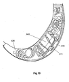
- Fig. 10 shows a further perspective view of a portion of the portable receiving unit of Fig. 9 , Again, the replaceable accumulator unit is provided in the slot 640 and serves as a power supply for the portable electronic receiving unit.
- the portable electronic receiving unit according to Fig. 9 and 10 can enter the loading trough 530 according to the Fig. 7 and 8th placed to charge the replaceable accumulator unit.
- the electrical contacts 535 come into contact with the electrical contact surfaces 511, so that the replaceable accumulator unit is charged in the portable electronic receiving unit via the charging contact surfaces on its front side.
Landscapes
- Engineering & Computer Science (AREA)
- Manufacturing & Machinery (AREA)
- Chemical & Material Sciences (AREA)
- Chemical Kinetics & Catalysis (AREA)
- Electrochemistry (AREA)
- General Chemical & Material Sciences (AREA)
- Charge And Discharge Circuits For Batteries Or The Like (AREA)
- Secondary Cells (AREA)
- Telephone Set Structure (AREA)
Abstract
Description
- Die vorliegende Erfindung betrifft eine austauschbare Akkumulatoreinheit, ein tragbares elektronisches Gerät und eine Ladestation.
- Auswechselbare Akkumulatoreinheiten werden in allen gängigen tragbaren elektronischen Geräten wie beispielsweise Mobiltelefone, PDAs oder dergleichen verwendet. Durch ihre Austauschbarkeit ist gewährleistet, dass eine defekte Akkumulatoreinheit ersetzt werden kann.
-
DE 10 2004 008 569 A1 zeigt eine eigensichere Energiestromversorgung für den untertägigen Bergbau. Hierbei wird eine auswechselbare Akkumulatoreneinheit mit einem Gehäuse und einer Lithium-Akkuzelle gezeigt. In dem Gehäuse ist ferner eine Schutzschaltung sowie eine Ladeschaltung vorgesehen. -
DE 298 17 827 U1 zeigt ein drahtloses Telefon mit einem Akku als Energieversorgung. Das Akku ist jedoch nicht austauschbar ausgestaltet. -
DE 296 10 085 U1 zeigt eine Akkumulatoreneinheit mit einem Gehäuse und austauschbaren Akkumulatorzellen sowie mindestens einem Ladekontakt. -
WO 2005/072548 A1 zeigt eine elektrisch beheizbare Einlegesohle. Die Einlegesohle weist dabei eine Heizelektrode und eine elektrisch damit verbundene aufladbare Batterie bzw. eine aufladbare Akkumulatorzelle auf. Hierbei ist die Akkumulatorzelle nicht austauschbar ausgestaltet. - Es ist Aufgabe der vorliegenden Erfindung, eine verbesserte austauschbare Akkumulatoreinheit und eine entsprechende Ladestation vorzusehen.
- Diese Aufgabe wird durch eine austauschbare Akkumulatoreinheit gemäß dem Anspruch 1 und durch eine Ladestation gemäß Anspruch 8 gelöst.
- Somit wird eine auswechselbare Akkumulatoreinheit mit einem Gehäuse und mindestens einer in dem Gehäuse angeordneten Lithium-Akkumulatorzelle vorgesehen. In dem Gehäuse der Akkumulatoreinheit ist ferner eine Ladeschaltung zum Steuern der Aufladung der Lithium-Akkumulatorzelle vorgesehen. An dem Gehäuse ist mindestens eine erste Ladekontakteinheit vorgesehen.
- Gemäß einem Aspekt der vorliegenden Erfindung weist die Akkumulatoreinheit eine Ladekontakteinheit an der Unterseite des Gehäuses und/oder an einer Stirnseite des Gehäuses auf. Somit werden zwei Ladekontakteinheiten vorgesehen, so dass die Akkumulatoreinheit in unterschiedlichen Anordnungen aufgeladen werden kann.
- Gemäß einem bevorzugten Aspekt der vorliegenden Erfindung weist die Ladekontakteinheit einen Massekontakt, einen positiven Anschluss zum Anschließen der Ladespannung, einen positiven Anschluss zum Vorsehen einer Versorgungsspannung der Akkumulatorzelle und einen Statuskontakt auf. Der positive Anschluss für die Ladespannung wird an die Ladeschaltung angelegt. Über den positiven Anschluss der Akkumulatoreinheit kann die Akkumulatoreinheit zur Spannungsversorgung verwendet werden.
- Die vorliegende Erfindung betrifft ebenfalls ein tragbares elektronisches Gerät, welches eine austauschbare Akkumulatoreinheit aufweist.
- Die Erfindung betrifft ebenfalls eine Ladestation für eine Akkumulatoreinheit. Die Ladestation weist einen ersten Schacht zur Aufnahme einer Akkumulatoreinheit auf. Die Ladestation weist ferner eine Lademulde zur Aufnahme eines tragbaren elektronischen Gerätes mit einer Akkumulatoreinheit und zur Aufladung der sich darin befindlichen austauschbaren Akkumulatoreinheit auf.
- Weitere Ausgestaltungen der Erfindung sind Gegenstand der Unteransprüche.
- Die Ausführungsbeispiele und Vorteile der vorliegenden Erfindung werden nachstehend unter Bezugnahme auf die beigefügten Zeichnungen näher erläutert.
- Fig. 1
- zeigt eine Seitenansicht einer Akkumulatoreinheit gemäß einem ersten Ausführungsbeispiel,
- Fig. 2
- zeigt eine Draufsicht auf die Akkumulatoreinheit von
Fig. 1 , - Fig. 3
- zeigt eine Ansicht der Unterseite der Akkumulatoreinheit von
Fig. 1 , - Fig. 4
- zeigt eine weitere Ansicht der Akkumulatoreinheit von
Fig. 1 , - Fig. 5
- zeigt eine schematische Ansicht der elektrischen Komponenten der Akkumulatoreinheit von
Fig. 1 , - Fig. 6
- zeigt eine schematische Darstellung der Akkumulatoreinheit von
Fig. 1 , - Fig. 7
- zeigt eine perspektivische Ansicht einer Ladestation gemäß einem zweiten Ausführungsbeispiel,
- Fig. 8
- zeigt eine weitere perspektivische Ansicht der Ladestation von
Fig. 7 , - Fig. 9
- zeigt eine perspektivische Ansicht eines elektronischen Gerätes gemäß einem dritten Ausführungsbeispiel, und
- Fig. 10
- zeigt eine vergrößerte Ansicht des elektronischen Gerätes von
Fig. 9 . -
Fig. 1 zeigt eine seitliche Ansicht der Akkumulatoreinheit gemäß einem ersten Ausführungsbeispiel. Die Akkumulatoreinheit weist ein oberes Gehäuseteil 10 und ein unteres Gehäuseteil 20 auf. An dem unteren Gehäuseteil 20 ist eine erste Ladekontakteinheit 100 mit vier Ladekontakten 11, 12, 13 und 14 angeordnet. Die Kontakttiefe der Ladekontakte 11 bis 14 beträgt zwischen 0,1mm und 1 mm, vorzugsweise 0,5 mm. -
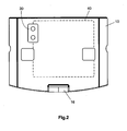
Fig. 2 zeigt eine Ansicht auf eine Akkumulatoreinheit gemäß dem ersten Ausführungsbeispiel vonFig. 1 . Hier ist insbesondere eine Draufsicht auf das obere Gehäuseteil 10 der Akkumulatoreinheit gezeigt. Auf dem oberen Gehäuseteil 10 ist ein Testpunktlabel 30 sowie ein Vorsprung 16 angeordnet. -
Fig. 3 zeigt eine weitere Ansicht der Akkumulatoreinheit vonFig. 1 . Hier ist eine Ansicht des unteren Gehäuseteils 20 gezeigt. In dem unteren Gehäuseteil 20 ist eine zweite Ladekontakteinheit 200 mit vier Ladekontakten 21, 22, 23 und 24 angeordnet. Diese Ladekontakte 21 bis 24 sind jeweils mit den Ladekontakten 11 bis 14 gekoppelt. - Das obere Gehäuseteil 10 und das untere Gehäuseteil 20 umschließen eine Lithium-Polymerakkuzelle 40. Das Gehäuse bestehend aus dem Oberteil 10 und dem Unterteil 20 weist zwei unterschiedliche Kontaktierungsebenen bzw. eine erste und zweite Ladekontakteinhit 100, 200 auf. Die eine Kontaktierungsebene befindet sich an der Unterseite, d. h. im unteren Gehäuseteil 20, wobei sich die zweite Kontaktierungsebene an der Rückseite bzw. einer Stirnseite der Akkumulatoreinheit. Durch die Ausgestaltung der zwei Ladekontakteinheiten 100, 200 bzw. Ladekontaktierungsebenen kann die Akkumulatoreinheit sowohl als ein Einzelakku in einem Ladefach als auch alternativ bzw. zusätzlich dazu in einem tragbaren elektronischen Gerät in einem Ladeschacht bzw. einer Lademulde entsprechend geladen werden.
- Die Akkumulatorzelle 40 weist eine Schutzschaltung gegen Kurzschluss und gegen eine zu hohe Spannung auf. Optional dazu kann eine Schutzschaltung gegen eine zu hohe Umgebungstemperatur ebenfalls in der Akkumulatoreinheit vorgesehen werden.
- In oder auf der Akkumulatorzelle wird eine Ladeschaltung vorgesehen, welche den Aufladeprozess der Akkumulatorzelle steuert. Diese Ladeschaltung kann eine Rückmeldung über den aktuellen Ladezustand der Akkumulatorzelle abgeben. Die Ladekontaktflächen an der Unterseite 20 und an der Rückseite weisen jeweils vier Ladekontaktflächen auf. Diese vier Ladekontaktflächen stellen Erde (Masse), + für die Ladespannung (die Spannung, welche an die Ladeschaltung angelegt wird), + für die Akkumulatorzelle (als Spannungsversorgung) und einen Statuskontakt dar. Über den Statuskontakt 12 kann eine Anzeige in der Ladestation angesteuert werden, um anzuzeigen, ob geladen wird oder ob die Akkumulatorzelle fertig aufgeladen ist. Alternativ bzw. zusätzlich dazu kann die Akkumulatoreinheit eine Anzeigeneinheit aufweisen, über die eine Restkapazität der Akkumulatorzelle angezeigt werden kann. Dies kann beispielsweise mittels einer Zeitanzeige, einer prozentualen Anzeige oder einer LED-Kette erfolgen.
- Durch das Vorsehen der Ladeschaltung innerhalb des Gehäuses der Akkumulatoreinheit befindet sich die gesamte Ladeintelligenz in der Akkumulatoreinheit, so dass eine entsprechende Ladestation lediglich eine stabilisierte Spannung von beispielsweise 5 Volt erzeugen muss.
-
Fig. 4 zeigt eine perspektivische Ansicht der Akkumulatoreinheit vonFig. 1 . Hier sind sowohl das obere als auch das untere Gehäuseteil 10, 20 als auch die erste Ladekontakteinheit 100 mit den vier Ladekontaktflächen 11-14 gezeigt. -
Fig. 5 zeigt eine schematische Ansicht der elektrischen Komponenten der Akkumulatoreinheit vonFig. 1 . Die Akkumulatorzelle 40 weist eine Lithium-Polymerzelle LI auf. In oder an der Lithium-Polymerzelle ist eine Ladeschaltung LS, eine Schutzschaltung SS und optional eine Umgebungstemperatur-Schutzschaltung USS angeordnet. Die Ladekontakteinheit 11-14 mit den vier Ladekontakten ist entsprechend mit der Polymerzelle 40 verbunden. Hierbei sind zwei unterschiedliche Ladekontakteinheiten an verschiedenen Gehäuseebenen angeordnet. Die beiden Ladekontakteinheiten sind jedoch elektrisch miteinander verbunden, so dass eine Aufladung der Akkumulatorzelle 40 über jede der Ladekontakteinheiten erfolgen kann. - Die Ladeschaltung LS ist beispielsweise als ein Ladecontroller zur Überwachung der Aufladung der Lithium-Polymerakkuzelle implementiert. Die Aufladung erfolgt hierbei zunächst vorzugsweise über einen konstanten Strom und anschließend über eine konstante Spannung. Vorzugsweise ist neben der Akkuzelle bzw. den Akkuzellen eine Leiterplatte angeordnet, welche sowohl die Ladeschaltung LS als auch die Schutzschaltung SS aufweist. Die Schutzschaltung SS weist eine Überwachungselektronik gegen einen Kurzschlussstrom und gegen eine Übe r-spannung auf. Durch die Implementierung der Ladeschaltung bzw. des Ladecontrollers in dem Gehäuse der Akkumulatoreinheit benötigt die Akkumulatoreinheit zur Aufladung lediglich eine konstante Spannung von 5 Volt. Die restliche Steuerung der Aufladung erfolgt durch die Ladeschaltung LS. Die Ladekontakteinheit 100 weist vier Ladekontaktflächen auf. Neben einer Kontaktfläche für die Masse ist ein Plus-Anschluss vorhanden, welcher direkt von der Akkumulatorzelle zu dem tragbaren elektronischen Gerät führt, um somit eine Energieversorgung des Gerätes sicherzustellen (+ für die Akkumulatorzelle). Zusätzlich dazu ist eine weitere Kontaktfläche vorgesehen, welche mit der Ladeschaltung LS gekoppelt ist. Diese Spannung weist typischerweise 5 Volt auf und stellt die Eingangsspannung für die Ladeschaltung LS dar. Aus dieser Eingangsspannung von ca. 5 Volt erzeugt die Ladeschaltung LS den konstanten Ladestrom und die konstante Ladespannung, mittels welcher die Akkumulatorzellen aufgeladen werden. Wie bereits oben angeführt, ist eine Kontaktfläche für die positive Spannung der Akkumulatorzelle vorgesehen, mittels welcher das tragbare elektronische Gerät mit Energie versorgt wird, so dass die Akkumulatoreinheit als Spannungsquelle verwendet wird. Der Statuskontakt ist mit der Ladeschaltung LS gekoppelt, welche entweder auf Plus oder auf Masse geschaltet wird. Diese Information ist über den Statuskontakt abfragbar. Diese beiden Betriebszustände (+ bzw. Versorgungsspannung und Masse) werden zum einen einem Ladezustand und zum anderen einem fertig aufgeladenen Zustand zugeordnet. Über den Statuskontakt kann die Information, ob die Akkumulatorzelle aufgeladen wird oder bereits aufgeladen ist, weitergegeben werden, so dass dies entsprechend in einer oder an einer Ladestation gezeigt werden kann.
- Die Ladekontaktflächen sind sowohl an der Stirnseite als auch an der unteren Seite der Akkumulatoreinheit vorgesehen. Dabei sind die Ladekontakte vorzugsweise als ein Formblechteil ausgestaltet, welches zwei unterschiedliche Kontaktebenen (Stirnseite, Unterseite) der Akkumulatoreinheit vorsieht. Somit kann die Akkumulatoreinheit sowohl von ihrer Stirnseite her als auch von ihrer Unterseite her aufgeladen werden.
-
Fig. 6 zeigt eine schematische Ansicht der Akkumulatoreinheit vonFig. 1 . Dabei ist insbesondere das obere Gehäuseteil 10, die Akkumulatorzelle 40 und das untere Gehäuseteil 20 gezeigt. An der Rückseite weist das untere Gehäuseteil 20 mehrere Vorsprünge auf, in welche die erste Ladekontakteinheit derart eingeführt werden kann, dass die unterschiedlichen Ladekontaktflächen zwischen den Vorsprüngen 25 platziert werden. In dem unteren Gehäuseteil 20 sind in dem Boden weitere Ausnehmungen vorgesehen, so dass eine Kontaktierung der Ladekontaktflächen auch an der Unterseite des Gehäuses möglich ist. -
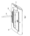
Fig. 7 zeigt eine perspektivische Ansicht einer Ladestation gemäß einem zweiten Ausführungsbeispiel. Die Ladestation wird vorzugsweise in einem Gehäuse 500 einer Sendeeinheit zum drahtlosen Senden an eine tragbare elektronische Empfangseinheit vorgesehen. In dem Gehäuse 500 ist ein Ladeschacht 540 für die austauschbaren Akkumulatoreneinheiten 510 gemäß dem ersten Ausführungsbeispiel vorgesehen. Dieser Ladeschacht ist vorzugsweise an einer Seitenfläche des Gehäuses 500 angeordnet. Auf der Oberseite des Gehäuses 500 ist vorzugsweise eine Lademulde 530 angeordnet, auf welcher ein tragbares elektronisches Empfangsgerät platziert werden kann, um eine sich darin befindliche austauschbare Akkumulatoreneinheit aufzuladen. -
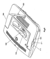
Fig. 8 zeigt eine weitere perspektivische Ansicht der Ladestation vonFig. 7 . In der Lademulde 530 sind elektrische Kontakte 535 vorgesehen, welche mit den Kontaktflächen von austauschbaren Akkumulatoreneinheiten in einem tragbaren elektronischen Gerät derart zusammenwirken können, dass die austauschbare Akkumulatoreinheit aufgeladen wird. An der Seite des Gehäuses 500 ist der Ladeschacht 540 vorgesehen, in welchem eine austauschbare Akkumulatoreinheit gemäß dem ersten Ausführungsbeispiel platziert werden kann, um somit aufgeladen zu werden. InFig. 8 sind die Ladekontaktflächen 511 an der Stirnseite der austauschbaren Akkumulatoreinheit gezeigt. Wenn die austauschbare Akkumulatoreinheit 510 in den Ladeschacht 540 eingeführt wird, so erfolgt eine Aufladung dieser Akkumulatoreinheit über die sich an der Unterseite befindlichen Ladekontakte, wie sie gemäß dem ersten Ausführungsbeispiel beschrieben worden sind. Demzufolge sind in dem Ladeschacht 540 elektrische Kontakte 545 vorgesehen, welche mit den Ladekontaktflächen an der Unterseite der Akkumulatoreinheit zusammenwirken. Der Ladeschacht 540 ist dabei vorzugsweise derart ausgestaltet, dass die austauschbaren Akkumulatoreinheiten gemäßFig. 1 , d. h. gemäß denFiguren 1 bis 6 , nur mit dem Vorsprung 16 nach oben weisend eingeführt werden können, so dass sichergestellt ist, dass die austauschbare Akkumulatoreinheit immer richtig herum eingeführt wird. -
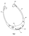
Fig. 9 zeigt eine perspektivische Ansicht einer tragbaren elektronischen Empfangseinheit gemäß einem dritten Ausführungsbeispiel. Die tragbare elektron i-sche Empfangseinheit weist ein Gehäuse 630 sowie zwei Stethoset-Arme 610 jeweils mit einem elektroakustischen Wandler 620 an deren Ende auf. An der Unterseite des Gehäuses 630 ist ein Schacht 640 vorgesehen, in welchen die austauschbare Akkumulatoreinheit 510 eingeführt werden kann, um die Energieversorgung für das drahtlose tragbare Empfangsgerät vorzusehen. In dem Schacht 640 sind elektrische Kontakte vorgesehen, welche mit den Ladekontaktflächen der austauschbaren Akkumulatoreinheit zusammenwirken können, so dass die Akkumulatoreinheit als Spannungsversorgung verwendet werden kann. -
Fig. 10 zeigt eine weitere perspektivische Ansicht eines Abschnitts der tragbaren Empfangseinheit vonFig. 9 . Auch hierbei ist die austauschbare Akkumulatoreinheit in dem Schacht 640 vorgesehen und dient als Spannungsversorgung für die tragbare elektronische Empfangseinheit. - Die tragbare elektronische Empfangseinheit gemäß
Fig. 9 und10 kann in die Lademulde 530 gemäß denFig. 7 und8 platziert werden, um die austauschbare Akkumulatoreinheit aufzuladen. In einem derartigen Fall kommen die elektrischen Kontakte 535 mit den elektrischen Kontaktflächen 511 in Berührung, so dass die austauschbare Akkumulatoreinheit in der tragbaren elektronischen Empfangseinheit über die Ladekontaktflächen an ihrer Stirnseite aufgeladen wird.
Claims (6)
- Austauschbare Akkumulatoreinheit, mit
einem Gehäuse (10, 20) und mindestens einer in dem Gehäuse angeordneten Lithiumakkumulatorzelle (40) und einer in dem Gehäuse angeordneten Ladeschaltungseinheit (50) zum Steuern der Aufladung der Lithiumakkumulatorzelle (40), dadurch gekennzeichnet, dass das Gehäuse eine erste Ladekontakteinheit (100, 200) an der Unterseite des Gehäuses (20, 10) und eine zweite Ladekontakteinheit (200) an einer Stimseite des Gehäuses (20, 10) aufweist,
wobei die erste und zweite Ladekontakteinheit (100, 200) elektrisch miteinander verbunden sind, so dass eine Aufladung der Akkumulatorzelle über jede der Ladekontakteinheiten erfolgen kann. - Akkumulatoreinheit nach Anspruch 1, wobei die Ladekontakteinheit (100, 200) vier Ladekontaktflächen (11-14; 21-24) aufweist.
- Akkumulatoreinheit nach einem der Ansprüche 1 oder 2, wobei die erste Ladekontaktfläche als Massekontaktierung, die zweite Ladekontaktfläche einen positiven Anschluss zum Anschließen der Ladespannung, der dritte Ladekontakt einen positiven Anschluss zum Vorsehen einer Versorgungsspannung für die Akkumulatorzelle und der vierte Ladekontakt einen Statuskontakt darstellt.
- Akkumulatoreinheit nach einem der Ansprüche 1 bis 3, wobei eine Anzeigeneinheit zum Anzeigen einer Restkapazität in dem Gehäuse angeordnet ist.
- Akkumulatoreinheit nach einem der Ansprüche 1 bis 4, wobei die Ladeschaltungseiriheit (50) als ein Ladecontroller zur Überwachung der Aufladung der Lithiumakkumulatorzelle (40) ausgestaltet ist, wobei die Ladeschaltungseinheit dazu ausgebildet ist, die Aufladung derart zu steuern, dass zunächst ein konstanter Strom und anschließend eine konstante Spannung der Lithiumakkumulatorzelle (40) zugeführt wird.
- Tragbares elektronisches Gerät mit einer austauschbaren Akkumulatoreinheit gemäß einem der Ansprüche 1 bis 5.
Applications Claiming Priority (2)
| Application Number | Priority Date | Filing Date | Title |
|---|---|---|---|
| DE102006014177A DE102006014177A1 (de) | 2006-03-24 | 2006-03-24 | Austauschbare Akkumulatoreinheit |
| PCT/EP2007/052811 WO2007110390A2 (de) | 2006-03-24 | 2007-03-23 | Austauschbare akkumulatoreinheit |
Publications (2)
| Publication Number | Publication Date |
|---|---|
| EP2002504A2 EP2002504A2 (de) | 2008-12-17 |
| EP2002504B1 true EP2002504B1 (de) | 2012-06-13 |
Family
ID=38438460
Family Applications (1)
| Application Number | Title | Priority Date | Filing Date |
|---|---|---|---|
| EP07727285A Not-in-force EP2002504B1 (de) | 2006-03-24 | 2007-03-23 | Austauschbare akkumulatoreinheit |
Country Status (7)
| Country | Link |
|---|---|
| US (1) | US8264199B2 (de) |
| EP (1) | EP2002504B1 (de) |
| CN (1) | CN101405913B (de) |
| CA (1) | CA2645776C (de) |
| DE (1) | DE102006014177A1 (de) |
| ES (1) | ES2387687T3 (de) |
| WO (1) | WO2007110390A2 (de) |
Family Cites Families (12)
| Publication number | Priority date | Publication date | Assignee | Title |
|---|---|---|---|---|
| US5216371A (en) * | 1989-06-12 | 1993-06-01 | Ricoh Company, Ltd. | Battery pack including measuring and indicating |
| US5694021A (en) * | 1994-02-28 | 1997-12-02 | Kabushiki Kaisha Toshiba | System for executing charge control of a secondary battery and detecting the capacitance thereof |
| EP0779693A1 (de) * | 1995-12-11 | 1997-06-18 | Yen-Ping Teng | Bauteilanordnung eines Batterieladegeräts für einen Telefon-Handapparat |
| DE29610085U1 (de) * | 1996-06-07 | 1996-08-14 | Tronico Toys Handels-GmbH, 40764 Langenfeld | Power Package |
| US6835491B2 (en) * | 1998-04-02 | 2004-12-28 | The Board Of Trustees Of The University Of Illinois | Battery having a built-in controller |
| DE29817827U1 (de) * | 1998-10-06 | 1999-02-11 | Schulz, André, 10557 Berlin | Drahtloses Telefon zum freihändigen Sprechen |
| US6326766B1 (en) * | 2000-06-09 | 2001-12-04 | Shoot The Moon Products Ii, Llc | Rechargable battery pack and battery pack charger with safety mechanisms |
| DE10059523A1 (de) | 2000-11-30 | 2002-06-27 | Infineon Technologies Ag | Schaltung zum Laden von Akkumulatoren |
| JP3546856B2 (ja) * | 2001-04-25 | 2004-07-28 | 松下電器産業株式会社 | 電池パック及び電池パックの故障診断方法 |
| DE102004006046A1 (de) * | 2004-02-02 | 2005-09-08 | Therm-Ic Products Gmbh | Elektrisch beheizbare Einlegesohle |
| DE102004008569A1 (de) * | 2004-02-19 | 2005-09-01 | Dbt Automation Gmbh | Eigensichere Batteriestromversorgung für den untertägigen Bergbau |
| US7408326B2 (en) * | 2005-04-08 | 2008-08-05 | Texas Instruments Incorporated | Battery pack system interface with multiple mode control states |
-
2006
- 2006-03-24 DE DE102006014177A patent/DE102006014177A1/de not_active Withdrawn
-
2007
- 2007-03-23 CN CN2007800102554A patent/CN101405913B/zh not_active Expired - Fee Related
- 2007-03-23 CA CA2645776A patent/CA2645776C/en active Active
- 2007-03-23 WO PCT/EP2007/052811 patent/WO2007110390A2/de not_active Ceased
- 2007-03-23 EP EP07727285A patent/EP2002504B1/de not_active Not-in-force
- 2007-03-23 US US12/294,236 patent/US8264199B2/en active Active
- 2007-03-23 ES ES07727285T patent/ES2387687T3/es active Active
Also Published As
| Publication number | Publication date |
|---|---|
| CN101405913A (zh) | 2009-04-08 |
| US8264199B2 (en) | 2012-09-11 |
| DE102006014177A1 (de) | 2007-09-27 |
| CA2645776A1 (en) | 2007-10-04 |
| CN101405913B (zh) | 2011-09-14 |
| EP2002504A2 (de) | 2008-12-17 |
| WO2007110390A3 (de) | 2008-06-26 |
| ES2387687T3 (es) | 2012-09-28 |
| US20090200990A1 (en) | 2009-08-13 |
| CA2645776C (en) | 2012-08-28 |
| WO2007110390A2 (de) | 2007-10-04 |
Similar Documents
| Publication | Publication Date | Title |
|---|---|---|
| EP1927147B1 (de) | Akkupack sowie elektrohandwerkzeuggerät | |
| DE102006061270A1 (de) | Batteriepack und Batteriemodul sowie Verfahren zum Betreiben eines Battiermoduls | |
| EP0777286A1 (de) | Batteriebetriebendes implantierbares Gerät | |
| DE102010013024A1 (de) | Batterie aus einer Vielzahl von Batterieeinzelzellen | |
| DE202012102971U1 (de) | Schutzhülle mit der Funktion zur umgekehrten Entladung eines Handheld-Gerätes | |
| WO2022258587A2 (de) | Modulares batteriesystem | |
| DE102020132334A1 (de) | Spielecontroller | |
| EP3364493A1 (de) | Akkupack mit temperatursensor | |
| EP2002504B1 (de) | Austauschbare akkumulatoreinheit | |
| DE102011014341A1 (de) | Kraftfahrzeugschlüssel und Verfahren zum Betreiben eines Kraftfahrzeugschlüssels | |
| DE102008013214B4 (de) | Ladesystem | |
| DE102021100154A1 (de) | Tastatureinrichtung und periphere Einrichtungskombination | |
| EP3503313A1 (de) | Mehrbatterie-adapter zur herstellung einer elektrischen verbindung zwischen mindestens zwei traktionsbatterien einerseits und einer antriebseinheit eines elektrofahrrades andererseits | |
| DE212016000163U1 (de) | Mobile Energiequelle | |
| EP1923933B1 (de) | Vorrichtung für die Energieversorgung | |
| DE102018102208A1 (de) | Mobile Ladestation für Elektrofahrzeuge und Verfahren zum Erden einer mobilen Ladestation | |
| DE102008003336A1 (de) | Transport-und/oder Aufbewahrungsbehälter für einen drahtlosen Hörer | |
| DE10143227B4 (de) | Vorrichtung zum Laden einer Batterie und wiederaufladbare Batterie | |
| DE2740944A1 (de) | Kontaktvorrichtung | |
| DE102006050622A1 (de) | Die Erfindung betrifft ein Ladegerät zum Aufladen von wieder aufladbaren Hörgeräten und ein enstprechendes Aufladeverfahren | |
| DE102004052505B4 (de) | Adaptervorrichtung für den Einsatz bei Ladegeräten für Akkus von Elektrohandwerkzeuggeräten | |
| EP3676930B1 (de) | Energiespeichersystem mit einem in einen passiven zustand schaltbaren energiespeicher | |
| EP2096515A2 (de) | Mobiler computer | |
| DE10163531C1 (de) | Verfahren und Vorrichtung für das Vorsehen von elektrischen Kontakten für Stromversorgungszellen | |
| DE102021116299A1 (de) | Energiespeicher, System und Verwendung eines Systems |
Legal Events
| Date | Code | Title | Description |
|---|---|---|---|
| PUAI | Public reference made under article 153(3) epc to a published international application that has entered the european phase |
Free format text: ORIGINAL CODE: 0009012 |
|
| AK | Designated contracting states |
Kind code of ref document: A2 Designated state(s): AT BE BG CH CY CZ DE DK EE ES FI FR GB GR HU IE IS IT LI LT LU LV MC MT NL PL PT RO SE SI SK TR |
|
| AX | Request for extension of the european patent |
Extension state: AL BA HR MK RS |
|
| 17P | Request for examination filed |
Effective date: 20081229 |
|
| RBV | Designated contracting states (corrected) |
Designated state(s): DE ES FR GB IT |
|
| RBV | Designated contracting states (corrected) |
Designated state(s): DE ES FR GB IT |
|
| 17Q | First examination report despatched |
Effective date: 20110211 |
|
| GRAP | Despatch of communication of intention to grant a patent |
Free format text: ORIGINAL CODE: EPIDOSNIGR1 |
|
| DAX | Request for extension of the european patent (deleted) | ||
| REG | Reference to a national code |
Ref country code: DE Ref legal event code: R079 Ref document number: 502007010054 Country of ref document: DE Free format text: PREVIOUS MAIN CLASS: H01M0010400000 Ipc: H01M0010460000 |
|
| RIC1 | Information provided on ipc code assigned before grant |
Ipc: H01M 10/46 20060101AFI20120117BHEP Ipc: H01M 10/052 20100101ALI20120117BHEP |
|
| GRAS | Grant fee paid |
Free format text: ORIGINAL CODE: EPIDOSNIGR3 |
|
| GRAA | (expected) grant |
Free format text: ORIGINAL CODE: 0009210 |
|
| AK | Designated contracting states |
Kind code of ref document: B1 Designated state(s): DE ES FR GB IT |
|
| REG | Reference to a national code |
Ref country code: GB Ref legal event code: FG4D Free format text: NOT ENGLISH |
|
| REG | Reference to a national code |
Ref country code: DE Ref legal event code: R096 Ref document number: 502007010054 Country of ref document: DE Effective date: 20120809 |
|
| REG | Reference to a national code |
Ref country code: ES Ref legal event code: FG2A Ref document number: 2387687 Country of ref document: ES Kind code of ref document: T3 Effective date: 20120928 |
|
| PLBE | No opposition filed within time limit |
Free format text: ORIGINAL CODE: 0009261 |
|
| STAA | Information on the status of an ep patent application or granted ep patent |
Free format text: STATUS: NO OPPOSITION FILED WITHIN TIME LIMIT |
|
| 26N | No opposition filed |
Effective date: 20130314 |
|
| REG | Reference to a national code |
Ref country code: DE Ref legal event code: R097 Ref document number: 502007010054 Country of ref document: DE Effective date: 20130314 |
|
| REG | Reference to a national code |
Ref country code: FR Ref legal event code: PLFP Year of fee payment: 10 |
|
| REG | Reference to a national code |
Ref country code: FR Ref legal event code: PLFP Year of fee payment: 11 |
|
| REG | Reference to a national code |
Ref country code: FR Ref legal event code: PLFP Year of fee payment: 12 |
|
| PGFP | Annual fee paid to national office [announced via postgrant information from national office to epo] |
Ref country code: IT Payment date: 20180322 Year of fee payment: 12 |
|
| PGFP | Annual fee paid to national office [announced via postgrant information from national office to epo] |
Ref country code: ES Payment date: 20180423 Year of fee payment: 12 |
|
| PG25 | Lapsed in a contracting state [announced via postgrant information from national office to epo] |
Ref country code: IT Free format text: LAPSE BECAUSE OF NON-PAYMENT OF DUE FEES Effective date: 20190323 |
|
| REG | Reference to a national code |
Ref country code: ES Ref legal event code: FD2A Effective date: 20200728 |
|
| PG25 | Lapsed in a contracting state [announced via postgrant information from national office to epo] |
Ref country code: ES Free format text: LAPSE BECAUSE OF NON-PAYMENT OF DUE FEES Effective date: 20190324 |
|
| PGFP | Annual fee paid to national office [announced via postgrant information from national office to epo] |
Ref country code: DE Payment date: 20240313 Year of fee payment: 18 Ref country code: GB Payment date: 20240322 Year of fee payment: 18 |
|
| PGFP | Annual fee paid to national office [announced via postgrant information from national office to epo] |
Ref country code: FR Payment date: 20240320 Year of fee payment: 18 |
|
| REG | Reference to a national code |
Ref country code: DE Ref legal event code: R081 Ref document number: 502007010054 Country of ref document: DE Owner name: SENNHEISER ELECTRONIC SE & CO. KG, DE Free format text: FORMER OWNER: SENNHEISER ELECTRONIC GMBH & CO. KG, 30900 WEDEMARK, DE |
|
| REG | Reference to a national code |
Ref country code: DE Ref legal event code: R119 Ref document number: 502007010054 Country of ref document: DE |
|
| GBPC | Gb: european patent ceased through non-payment of renewal fee |
Effective date: 20250323 |
|
| PG25 | Lapsed in a contracting state [announced via postgrant information from national office to epo] |
Ref country code: DE Free format text: LAPSE BECAUSE OF NON-PAYMENT OF DUE FEES Effective date: 20251001 |
|
| PG25 | Lapsed in a contracting state [announced via postgrant information from national office to epo] |
Ref country code: GB Free format text: LAPSE BECAUSE OF NON-PAYMENT OF DUE FEES Effective date: 20250323 |
|
| PG25 | Lapsed in a contracting state [announced via postgrant information from national office to epo] |
Ref country code: FR Free format text: LAPSE BECAUSE OF NON-PAYMENT OF DUE FEES Effective date: 20250331 |