EP2002134B1 - Verbesserte gleitlagerung für einen eisenbahnzugmotor - Google Patents
Verbesserte gleitlagerung für einen eisenbahnzugmotor Download PDFInfo
- Publication number
- EP2002134B1 EP2002134B1 EP07841787.0A EP07841787A EP2002134B1 EP 2002134 B1 EP2002134 B1 EP 2002134B1 EP 07841787 A EP07841787 A EP 07841787A EP 2002134 B1 EP2002134 B1 EP 2002134B1
- Authority
- EP
- European Patent Office
- Prior art keywords
- wick
- supplemental
- journal
- axle
- Prior art date
- Legal status (The legal status is an assumption and is not a legal conclusion. Google has not performed a legal analysis and makes no representation as to the accuracy of the status listed.)
- Not-in-force
Links
- 230000000153 supplemental effect Effects 0.000 claims description 33
- 230000001050 lubricating effect Effects 0.000 claims description 14
- 239000012530 fluid Substances 0.000 claims description 9
- 230000006835 compression Effects 0.000 claims description 5
- 238000007906 compression Methods 0.000 claims description 5
- 230000003137 locomotive effect Effects 0.000 claims description 4
- 239000000314 lubricant Substances 0.000 claims description 3
- 238000005461 lubrication Methods 0.000 description 16
- 239000000835 fiber Substances 0.000 description 12
- 230000004048 modification Effects 0.000 description 6
- 238000012986 modification Methods 0.000 description 6
- 239000000463 material Substances 0.000 description 5
- 230000004323 axial length Effects 0.000 description 3
- 230000008014 freezing Effects 0.000 description 2
- 238000007710 freezing Methods 0.000 description 2
- 238000009825 accumulation Methods 0.000 description 1
- 230000001154 acute effect Effects 0.000 description 1
- 239000000853 adhesive Substances 0.000 description 1
- 238000004026 adhesive bonding Methods 0.000 description 1
- 230000001070 adhesive effect Effects 0.000 description 1
- 239000003795 chemical substances by application Substances 0.000 description 1
- 239000002131 composite material Substances 0.000 description 1
- 238000010276 construction Methods 0.000 description 1
- 239000006185 dispersion Substances 0.000 description 1
- 230000000694 effects Effects 0.000 description 1
- 230000005484 gravity Effects 0.000 description 1
- 230000014759 maintenance of location Effects 0.000 description 1
- 230000001105 regulatory effect Effects 0.000 description 1
- 230000000717 retained effect Effects 0.000 description 1
- XLYOFNOQVPJJNP-UHFFFAOYSA-N water Substances O XLYOFNOQVPJJNP-UHFFFAOYSA-N 0.000 description 1
- 238000009736 wetting Methods 0.000 description 1
- 210000002268 wool Anatomy 0.000 description 1
Images


Classifications
-
- F—MECHANICAL ENGINEERING; LIGHTING; HEATING; WEAPONS; BLASTING
- F16—ENGINEERING ELEMENTS AND UNITS; GENERAL MEASURES FOR PRODUCING AND MAINTAINING EFFECTIVE FUNCTIONING OF MACHINES OR INSTALLATIONS; THERMAL INSULATION IN GENERAL
- F16C—SHAFTS; FLEXIBLE SHAFTS; ELEMENTS OR CRANKSHAFT MECHANISMS; ROTARY BODIES OTHER THAN GEARING ELEMENTS; BEARINGS
- F16C33/00—Parts of bearings; Special methods for making bearings or parts thereof
- F16C33/02—Parts of sliding-contact bearings
- F16C33/04—Brasses; Bushes; Linings
- F16C33/06—Sliding surface mainly made of metal
- F16C33/10—Construction relative to lubrication
- F16C33/1025—Construction relative to lubrication with liquid, e.g. oil, as lubricant
- F16C33/103—Construction relative to lubrication with liquid, e.g. oil, as lubricant retained in or near the bearing
-
- B—PERFORMING OPERATIONS; TRANSPORTING
- B61—RAILWAYS
- B61C—LOCOMOTIVES; MOTOR RAILCARS
- B61C17/00—Arrangement or disposition of parts; Details or accessories not otherwise provided for; Use of control gear and control systems
- B61C17/08—Lubrication systems
-
- B—PERFORMING OPERATIONS; TRANSPORTING
- B61—RAILWAYS
- B61C—LOCOMOTIVES; MOTOR RAILCARS
- B61C9/00—Locomotives or motor railcars characterised by the type of transmission system used; Transmission systems specially adapted for locomotives or motor railcars
- B61C9/38—Transmission systems in or for locomotives or motor railcars with electric motor propulsion
-
- F—MECHANICAL ENGINEERING; LIGHTING; HEATING; WEAPONS; BLASTING
- F16—ENGINEERING ELEMENTS AND UNITS; GENERAL MEASURES FOR PRODUCING AND MAINTAINING EFFECTIVE FUNCTIONING OF MACHINES OR INSTALLATIONS; THERMAL INSULATION IN GENERAL
- F16C—SHAFTS; FLEXIBLE SHAFTS; ELEMENTS OR CRANKSHAFT MECHANISMS; ROTARY BODIES OTHER THAN GEARING ELEMENTS; BEARINGS
- F16C17/00—Sliding-contact bearings for exclusively rotary movement
- F16C17/02—Sliding-contact bearings for exclusively rotary movement for radial load only
-
- F—MECHANICAL ENGINEERING; LIGHTING; HEATING; WEAPONS; BLASTING
- F16—ENGINEERING ELEMENTS AND UNITS; GENERAL MEASURES FOR PRODUCING AND MAINTAINING EFFECTIVE FUNCTIONING OF MACHINES OR INSTALLATIONS; THERMAL INSULATION IN GENERAL
- F16C—SHAFTS; FLEXIBLE SHAFTS; ELEMENTS OR CRANKSHAFT MECHANISMS; ROTARY BODIES OTHER THAN GEARING ELEMENTS; BEARINGS
- F16C33/00—Parts of bearings; Special methods for making bearings or parts thereof
- F16C33/02—Parts of sliding-contact bearings
- F16C33/04—Brasses; Bushes; Linings
- F16C33/06—Sliding surface mainly made of metal
- F16C33/10—Construction relative to lubrication
- F16C33/1025—Construction relative to lubrication with liquid, e.g. oil, as lubricant
- F16C33/106—Details of distribution or circulation inside the bearings, e.g. details of the bearing surfaces to affect flow or pressure of the liquid
- F16C33/1065—Grooves on a bearing surface for distributing or collecting the liquid
-
- F—MECHANICAL ENGINEERING; LIGHTING; HEATING; WEAPONS; BLASTING
- F16—ENGINEERING ELEMENTS AND UNITS; GENERAL MEASURES FOR PRODUCING AND MAINTAINING EFFECTIVE FUNCTIONING OF MACHINES OR INSTALLATIONS; THERMAL INSULATION IN GENERAL
- F16C—SHAFTS; FLEXIBLE SHAFTS; ELEMENTS OR CRANKSHAFT MECHANISMS; ROTARY BODIES OTHER THAN GEARING ELEMENTS; BEARINGS
- F16C33/00—Parts of bearings; Special methods for making bearings or parts thereof
- F16C33/02—Parts of sliding-contact bearings
- F16C33/04—Brasses; Bushes; Linings
- F16C33/18—Sliding surface consisting mainly of wood or fibrous material
-
- F—MECHANICAL ENGINEERING; LIGHTING; HEATING; WEAPONS; BLASTING
- F16—ENGINEERING ELEMENTS AND UNITS; GENERAL MEASURES FOR PRODUCING AND MAINTAINING EFFECTIVE FUNCTIONING OF MACHINES OR INSTALLATIONS; THERMAL INSULATION IN GENERAL
- F16C—SHAFTS; FLEXIBLE SHAFTS; ELEMENTS OR CRANKSHAFT MECHANISMS; ROTARY BODIES OTHER THAN GEARING ELEMENTS; BEARINGS
- F16C33/00—Parts of bearings; Special methods for making bearings or parts thereof
- F16C33/02—Parts of sliding-contact bearings
- F16C33/04—Brasses; Bushes; Linings
- F16C33/24—Brasses; Bushes; Linings with different areas of the sliding surface consisting of different materials
-
- F—MECHANICAL ENGINEERING; LIGHTING; HEATING; WEAPONS; BLASTING
- F16—ENGINEERING ELEMENTS AND UNITS; GENERAL MEASURES FOR PRODUCING AND MAINTAINING EFFECTIVE FUNCTIONING OF MACHINES OR INSTALLATIONS; THERMAL INSULATION IN GENERAL
- F16C—SHAFTS; FLEXIBLE SHAFTS; ELEMENTS OR CRANKSHAFT MECHANISMS; ROTARY BODIES OTHER THAN GEARING ELEMENTS; BEARINGS
- F16C2326/00—Articles relating to transporting
- F16C2326/10—Railway vehicles
Definitions
- the present invention relates to a friction support bearing for a railway locomotive traction motor in accordance with the pre-characterising portion of claim 1.
- a friction support bearing is known from US 2006/0013518 .
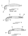
- FIG. 1 and 4 A conventional railway locomotive pinion-end (PE) traction-motor support bearing, such as that disclosed in U.S. Patent No. 5,038,631 , is shown in Figs. 1 and 4 , which Figs. 1 and 4 show the half of the support bearing 10 that contains the window 12 for passing a lubricating wick.
- the load zones for loading the truck axle-journal should be centered. This is so in order that the lubricating wick (not shown) entering the interior of the bearing via the wick window or opening 12 lubricates all contacting surface-areas, which lubricating wick contacts the axle-journal through the window.
- both load zones should be contained within the total axial dimension of the wick if possible, again in order to ensure the best possible lubrication.
- Each traction-motor sleeve bearing has two load zones, an upper one and a lower one, and these tend to be heaviest around 25° from vertical because of commonly-used 25° gear-tooth pressure angle.
- Both load-contact patterns can be seen in the window half 10 of the PE bearing with the upper load pattern above the lubricator access-window and the lower load pattern below the window.
- both upper and lower load contact-patterns should be centered at mid-length of the window, in order that the wick lubricator provides the best possible lubrication.
- both load contact-patterns should be contained within the total axial dimension or limits of the wick lubricator if possible, again to ensure the best possible lubrication.
- the lubricating wick of the conventional sleeve bearing shown in Figs. 1 and 4 enters the bearing from the lubrication sump through a cast opening in the axle cap, which is aligned with the window or opening 12 in the bearing liner.
- This opening 12 is centered axially on the journal and the wick protrudes through this opening to contact the axle-journal at a position approximately 20°- 30° below a horizontal line passing through the axle gear and pinion center lines.
- the sleeve bearing 10 also has a flange wick 16 for lubricating the flange-end 20.
- the axial length of the preferred journal-to-liner contact area is defined by the axial length of the wick.
- the bearing liners are machined in such a way as to relieve the liners so that journal contact under normal loads remains in the wick-wetted axial area 14. In many traction motor support bearings, however, the envelope available for supporting the journal is significantly longer in the axial direction than the wick and the length of wetted area.
- Pinion-end sleeve bearing load ratings are frequently limited by the axial length that can be reliably lubricated by the lubrication delivery system. If lubrication can be assured beyond the axial dispersion of conventional support bearings, that additional length may become useful for supporting the journal. By reducing the unit loading of the original journal and thereby increasing the load capacity, the criticality of other parameters affecting wear rate and reliability arc lessened.
- auxiliary wicks may, under certain circumstances adhere to the face of the axle-journal, which may cause part of the auxiliary wick pad to be torn away during the axle-rotation.
- additional lubrication provided by these auxiliary wicks may be better enhanced by more direct fluid communication with the respective flinger grooves which provides the lubricant supply wetting the pad faces of these auxiliary wicks.
- a more optimal configuration of each auxiliary wick would be helpful in increasing the wick life.
- the sleeve bearing is provided with the ability to provide additional lubrication to the lateral areas beyond the width of the main supply wick by the addition of additional wicks one on either axial side of the central wick or by incorporating passageways near the 6:00 location on either axial side capable of communicating with the oil accumulated in the oil flinger grooves and taking advantage of the oil-flinger rotating lift capability and lateral movement within the bearing lateral clearances for providing additional lubrication and for extending the envelope of the wetted area available for supporting the truck-axle-journal in the axial direction.
- each auxiliary wick is constructed of felt in which the length of the felt fibers constituting the wick pad are oriented in a direction perpendicular to the longitudinal axis of the axle-journal so that only contact of the ends of the felt-fibers are in contact with the journal-surface.
- the auxiliary wick is provided with a projecting tail-portion that projects into the narrow gap connecting the wick-receiving and mounting opening to its respective flinger groove, in order to ensure lubrication and saturation of the respective auxiliary wick from its associated flinger groove.
- the auxiliary wick is provided with a tapered cross-sectional or concave shape that allows the wick-pad to expand within its wick-receiving and mounting opening, as well as making the auxiliary wick-pad of softer felt in a durometer-hardness range less than that previously used.
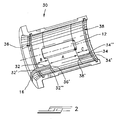
- a railway-locomotive traction motor friction support or sleeve bearing indicated generally by reference numeral 30.
- the shown friction support bearing does not employ flinger grooves.
- Flinger grooves mount flinger rings which, when employed, help to redistribute the oil back to the oil reservoir and reduce oil loss, as disclosed in U.S. Patent No. 3,905,659 .
- the sleeve bearing 30 is provided with a conventional central wick window 12, as explained herein above with regard to Figs. 1 and 4 , and, in addition, at least two supplemental or auxiliary wicks, one wick 32 at the outboard end and one wick 34 at the inboard end.
- the supplemental wicks 32, 34 are oriented at 6:00 O'clock when viewing Fig. 2 .
- the outboard wick 32 is combined with the currently-used flange wick 16, also explained above with reference to the prior-art bearing of Figs. 1 and 4 .
- the wicks 32, 34 are lubricated via lateral flow oil collection grooves 36, 38, respectively, which arc used, as in the conventional manner, for collecting oil, as explained in U.S. Patent No. 4,229,056 .
- the provision of these additional wicks 32, 34 extend the effective length of the wetted area of the bearing to the areas encompassed by areas A, B and C in Fig.
- the simple reliable oil supply system 36, 38 is used. This system collects the lateral oil discharge from the loaded central region serviced by the conventional central wick and delivers the oil to those journal areas beyond the main wick wetted axial area via these additional wicks 34, 36. Thus, these oil collection grooves 36, 38 also serve the additional function of providing for this additional lubrication of the extended contact areas B and C.
- the supplemental wick 32 is narrower than the corresponding flange wick 16, although, if necessary, it may be the same or even greater in width.
- Each supplemental wick 32, 34 has a first overlapping portion 32', 34', respectively, that is received within the interior of a respective channel 36, 38, and a main longitudinal portion or section 32", 34" extending longitudinally axially in a direction toward the center of the friction bearing. With each overlapping portion 32', 34' positioned in the interior of the respective groove, each groove 36, 38 acts as a sump or reservoir for the additional wicks 32, 34.
- each wick 32, 34 is received or mounted in a recess or pocket formed in the interior shell of the friction bearing of similar shape as that of the additional wick 32, 34, in a manner similar to shown in the embodiment of Fig. 8 as described hereinbelow.
- Each pocket has a depth less than that of the thickness of the respective additional wick 32, 34, so that each wick 32, 34 projects or protrudes out from the respective pocket, and interiorly toward the axle-journal mounted in the bearing, for contact against the juxtapositioned surfaces of the journal located within the lateral extent of the above-mentioned contact areas B and C.
- FIG. 3 and 6 there is shown another known sleeve bearing more particularly a friction bearing provided with flinger grooves, but without the oil collection grooves 36, 38 of the bearing of Figs. 2 and 5 .
- the friction support bearing of this embodiment is indicated generally by reference numeral 40, and, as shown, utilizes conventional flinger grooves 42, 44.
- the flinger grooves 42, 44 in addition to serving their conventional function of mounting the flinger rings, as disclosed in U.S. Patent No. U.S. Patent No. 3,905,659 , also serve the function of the lateral-flow oil-collection grooves for the additional wicks 52, 54.
- the additional wicks 52, 54 are oriented at 6:00 O'clock when viewing Fig.
- wick 56 is conventionally mounted.
- the additional wicks 52, 54 are the same as the wicks 32, 34 of Fig. 2 , and are mounted in pockets or recesses similar to those shown in Fig. 8 discussed below.
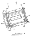
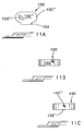
- FIG. 7 there is shown another known friction support bearing 60 in which, instead of using the additional wicks of Figs. 2 and 3 to lubricate the additional surface contact areas B and C, oil-flow passageways 62, 64 forming a V-shape are provided on the flange or outboard end, and oil-flow passageways 66, 68 forming a V-shape are provided on the inboard end. These passageways are oriented approximately at 6:00 O'clock when viewing Fig. 7 .
- the friction bearing 60 is provided with both oil-collection grooves 70, 72 and flinger grooves 74, 76, in a manner disclosed in U.S. Patent No.
- Each passageway opens into the interior of a respective flinger grooves 74, 76 for fluid communication therewith, and, thus, effectively serve as oil-flow extension grooves of the flinger grooves.
- the V-shaped passageways 62, 64, and the V-shaped passageways 66, 68 form an acute angle therebetween, as seen in Fig. 7 , and preferably is in the range of between 15 degrees to 45 degrees, although this is not meant to be limiting.
- This modification takes advantage of the proven collection and return system of the conventional inboard and outboard ends of the bearing liner by using the flinger rings to cause oil to flow into the oil recirculation grooves and hence to be delivered to the bearing lateral areas both at the inboard and outboard ends of the bearing liner beyond that wetted by the main delivery wick. While two such passageways have been shown which are V-shaped, more than two such passageways may be employed without a V-shaped configuration.
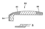
- Fig. 8 there is shown another known friction support bearing in which no flinger grooves or oil collection grooves are included in the friction bearing 80.
- the outboard supplemental wick 82 is connected to the flange wick 84 to form one continuous wick.
- the inboard supplemental wick 86 is the same as shown in Figs. 2 and 3 . Since the wicks are located at the 6:00 operating position, they would, therefore, receive their lubrication as a result of the natural gravity drainage accumulation from the journal wetted surfaces any time the axle would be at rest.
- the normal supply wick delivers a band of oil on the axle.
- the supplemental or auxiliary wicks inboard ends would overlap this wetted band and take a portion of this oil to extend the wetted band width.
- a further known friction support bearing 90 which incorporates both flinger grooves and oil-collection grooves.
- the supplemental or auxiliary wicks 92 are received in pockets or recesses 36' formed in the interior shell of the friction bearing.
- Each pocket has a depth less than that of the thickness of the respective additional wick, so that each wick projects or protrudes out from the respective pocket, and interiorly toward the axle journal mounted in the bearing, for contact against the juxtapositioned surfaces of the journal located within the lateral extent of the above-mentioned contact areas B and C.
- Each pocket 36' has an open end 96 that is in fluid communication with the interior of a respective flinger groove 98 for lubricating the respective supplemental or auxiliary wick in a manner similar to the embodiment of Fig. 3 . It is also noted that corners 36", 38" of the pockets are rounded to ensure that the wicks are maintained therein.
- supplemental or auxiliary wicks allows reduced-width flinger grooves as compared to the prior art friction support bearings, and also allows for the flingers grooves to be moved farther away from the center wick. Also, it is also possible to have a version of the invention where the flinger grooves and the outboard oil-collection groove are eliminated, which would extend the usable load-carrying width approximately one more inch.
- the width of the crowned load-bearing surface area was increased to approximately 13,16 cm (5.18 in) as compared to 9.55 cm (3.76 in) for the conventional bearing.
- each supplemental or auxiliary wick was approximately 3,18 cm (1.25 in) in length taken in the direction parallel to the annular flinger groove. and .81 in.
- auxiliary wick 100 is similar to that of the auxiliary wick 92, except that the auxiliary wick 100 is provided with a tail-section 102 which projects from the front in a direction toward the flinger groove 98.
- the tail-section 102 fits snugly, and may be adhesively secured, in the open end or entrance, 104' of the pocket 104. While the outboard auxiliary wick has been shown in Fig. 10 , the same holds for the inboard end, as described hereinabove.
- the tail-section 102 for each of the outboard and inboard auxiliary wicks, greater lubrication and saturation of the pad will ensue owing to the tail-section 102, and therefore the auxiliary wick 100 proper, being in direct fluid contact with the lubricant flowing in the flinger grooves.
- the end-walls or end-surfaces 100', 100" of the auxiliary wick 100 are more curved so that the main body proper of the wick 100 is approximately oblong or elliptical in shape. This shape helps to retain the wick 100 in its pocket 104.
- the ends 106, 108 of the pocket 104 are also appropriately shaped to match those of the wick 100, whereby the pocket 104 is generally oblong or elliptical in shape.
- the auxiliary wick 100 has an overall total length taken between 100' and 100" of approximately 3,18 cm (1.25 inches), a width (without a tail-section) of approximately 1,59 cm (5/8 inch), and a depth of approximately 0,90 cm (.354 inch), with a tail-section 102 of a length taken in the same direction as the length of the wick 100 of 1,59 cm (5/8 inch) and width of 0,32 cm (1/8 inch). It is, of course, to be understood that these dimensions may be varied in accordance with various requirements and factors, and are not meant to be limiting.
- the auxiliary wicks of Fig. 9 or Fig. 10 may be provided with upwardly-tapering ends 112, 114 in order that there arc provided ever-increasing lateral clearances between these ends 112, 114 and the corresponding end walls 106, 108 of the pocket 104 of the embodiment of Fig. 10 , or of the corresponding end walls of the pocket 36' shown in Fig. 9 .
- the provision of upwardly-tapered ends allows for the auxiliary wick to expand within its respective pocket or cavity 36' or 104 during contact of the wick-face 102" with the surface of the rotating axle-journal and also provide more constant biasing force against the surface of the axle-journal..
- the surface-to-surface contact of the wick-face of the auxiliary wick with the surface of axle-journal causes the felt pad of the auxiliary wick to compress.
- the compression of the wick pad will be accommodated by outward expansion of the auxiliary wick, thereby providing "give" upon the presence of compressions forces during operational contact with the rotating surface of the axle-journal in which the wick. Without such clearances, there is the possibility that excessive surface-to-surface contact and forces would considerably shorten the life of the wick or damage it.
- Each end 112, 114 of the auxiliary wick 110 preferably has a taper of approximately five degrees relative to an end wall 108 or 110, but it may vary from being close to zero up to ten degrees.
- the taper of course, is zero.
- five degrees is preferred, though other angles may be used.
- each auxiliary wick may be alternatively cross-sectioned such that the end walls are at least partially upwardly and inwardly extending in order to provide clearances between its ends walls and the end walls of the pocket in which it is mounted.
- a cross-section defining ends 112, 114 that are concave-shaped may also be used, which would also allow for clearances for expansion of the wick.
- Each additional wick 32, 92, and 100 is made of felt material or other comparable composite materials, in order to optimize retention and to provide enhanced capillary effect.
- the width of each additional wick 32, 92 is preferably less than the width of the flange wick, although such does not preclude the same or greater width.
- the supplemental wicks are preferably retained by adhesives, or, alternatively, by the geometry of the machined pockets or grooves which also act as reservoirs in combination with the wick geometry.
- each auxiliary wick is cut from an SAE F-10 high grade, medium low density felt of 182,9 cm (72 inches) in width having the following specifications: minimum wool content of 95%, water soluble max.
- Such felt is sold by, for example, Southeastern Felt and Supply Co. of Concord, N.C., or Aetna Felt Corp. of Allentown, PA. However, it is to be understood that felt of different grade and specification may be used if it provides the requirements that allow for the auxiliary lubrication of the surface of axle-journal as described hereinabove.
- the durometer hardness of this felt material is preferably of a specification indicating a softer material in order to reduce felt wick-face pressure against the axle-journal, to thus generate less heat through friction.
- the felt is not cut in usual manner along which, conventionally, is transverse the direction or length of the felt fibers making up the felt. Instead, the supply of felt is cut along, or parallel, to the length of the fibers constituting the supply felt, as shown in Fig. 13 .
- the auxiliary wicks or pads are cut from a supply of felt 120 in a direction such that the fibers of each pad extend in a longitudinally axial direction from the bottom surface 102' toward the upper axle-journal-engaging surface 102".
Landscapes
- Engineering & Computer Science (AREA)
- General Engineering & Computer Science (AREA)
- Mechanical Engineering (AREA)
- Chemical & Material Sciences (AREA)
- Oil, Petroleum & Natural Gas (AREA)
- Transportation (AREA)
- Life Sciences & Earth Sciences (AREA)
- Wood Science & Technology (AREA)
- Automation & Control Theory (AREA)
- Combustion & Propulsion (AREA)
- Sliding-Contact Bearings (AREA)
- Motor Or Generator Frames (AREA)
Claims (3)
- Gleitlager für den Antriebsmotor einer Eisenbahnlokomotive, aufweisend ein Hauptlagergehäuse mit einem Innenendteil und einem Außenendteil, einem zentralen Dochtfenster (12) für einen zentralen Schmierdocht, einer Innenfläche (14), die mindestens teilweise zur Berührung durch einen Achszapfen vorgesehen ist, wobei das äußere Ende der Innenfläche eine Ölnut (36, 42, 70) und auch das innere Ende der Innenfläche eine Ölnut (38, 44, 72) enthalten und vorgesehen sind:ein erster äußerer zusätzlicher Schmierdocht (32, 52, 82) am Außenendteil und ein zweiter innerer zusätzlicher Schmierdocht (34, 54, 86) am Innen-endteil zur zusätzlichen Schmierung der Berührungsfläche zwischen der Innenfläche und dem Achszapfen axial über die Grenzen des Zentral-Schmierdochts hinaus;wobei jeder der ersten und zweiten Zusatz-Schmierdochte (32, 52, 82; 34, 54, 86) jeweils etwa in der 6:00-Uhr-Position des Hauptlagergehäuses liegen;wobei jeder der ersten und zweiten Zusatz-Schmierdochte (32, 52, 82; 34, 54, 86) jeweils in Strömungsverbindung mit einer zugeordneten der Ölnuten (36, 42, 70; 38, 44, 72) stehen und von dieser her axial einwärts verlaufen; und wobeidie Innenfläche am inneren Ende eine Tasche zur Aufnahme des zweiten inneren Zusatz-Schmierdochts (34, 54, 86) und am äußeren Ende eine Tasche zur Aufnahme des ersten äußeren Zusatz-Schmierdochts (32, 52, 82) enthält, die Aufnahmetaschen jeweils von einer zugehörigen der Ölnuten (36, 42, 70) axial weg verlaufen und weniger tief sind als der jeweils zugehörige erste bzw. zweite Zusatz-Schmierdocht (32, 52, 82; 34, 54, 86) dick ist, so dass der erste und der zweite Zusatz-Schmierdocht (32, 52, 82; 34, 54, 86) jeweils einen angrenzenden Teil eines dort liegenden Achszapfens berühren können; und wobei die Aufnahmetaschen weiterhin jeweils eine Einlauföffnung aufweisen, die in eine zugehörige der Ölnuten (36, 42, 70; 38, 44, 72) mündet und mit ihr fluidisch verbunden ist, damit eine Strömungsverbindung des zugehörigen ersten bzw. zweiten Zusatz-Schmierdochts und dem Inneren der jeweiligen Ölnut entsteht;dadurch gekennzeichnet, dass
der erste und der zweite Zusatz-Schmierdocht (32, 52, 82; 34, 54, 86) jeweils einen Hauptteil mit einer oberen Dochtfläche zum Berühren einer Oberfläche eines Achszapfens, eine untere Dochtfläche sowie ein Paar Endflächen aufweisen; und dass mindestens einige Teile der Endflächen des Hauptteils jedes der ersten und zweiten Zusatz-Schmierdochte (32, 52, 82; 34, 54, 86) von den Endwänden einer zugehörigen der Aufnahmetaschen beabstandet sind, um einen Spielraum zwischen den Endflächen und den Endwänden der jeweiligen Aufnahmetasche herzustellen, so dass, wenn im Einsatz der Zusatz-Schmierdocht komprimiert wird, er sich in der zugehörigen Aufnahmetasche ausdehnen kann. - Gleitlager nach Anspruch 1, bei dem die Endflächen (112, 114) aufwärts verjüngt sind, um zwischen den Endflächen und den Endwänden (106, 108) der Aufnahmetasche (104) einen Zwischenraum herzustellen.
- Gleitlager nach Anspruch 1, bei dem der Hauptteil des ersten und zweiten Zusatz-Schmierdochts (32, 52, 82; 34, 54, 86) weiterhin jeweils einen vorwärts gewandten Ansatz (102) aufweist, der Hauptteil der Aufnahmetaschen jeweils etwa die gleiche Gestalt wie der Zusatz-Schmierdocht und die Endwände aufweist sowie eine Einlauföffnung enthält, die in Strömungsverbindung mit einer zugehörigen der Ölnuten (36, 42, 70) steht, und der Ansatz in die Einlauföffnung eingesetzt ist, so dass der Zusatz-Schmierdocht stetig von Schmierstoff getränkt wird, der in der zugehörigen Ölnut umläuft.
Applications Claiming Priority (2)
| Application Number | Priority Date | Filing Date | Title |
|---|---|---|---|
| US11/680,729 US7603955B2 (en) | 2005-07-11 | 2007-03-01 | Sleeve bearing for railway traction motor |
| PCT/US2007/077488 WO2008105926A1 (en) | 2007-03-01 | 2007-09-04 | Improved sleeve bearing for railway traction motor |
Publications (3)
| Publication Number | Publication Date |
|---|---|
| EP2002134A1 EP2002134A1 (de) | 2008-12-17 |
| EP2002134A4 EP2002134A4 (de) | 2012-08-08 |
| EP2002134B1 true EP2002134B1 (de) | 2013-11-06 |
Family
ID=39745163
Family Applications (1)
| Application Number | Title | Priority Date | Filing Date |
|---|---|---|---|
| EP07841787.0A Not-in-force EP2002134B1 (de) | 2007-03-01 | 2007-09-04 | Verbesserte gleitlagerung für einen eisenbahnzugmotor |
Country Status (10)
| Country | Link |
|---|---|
| US (2) | US7603955B2 (de) |
| EP (1) | EP2002134B1 (de) |
| CN (2) | CN102635634B (de) |
| AU (1) | AU2007347710B2 (de) |
| BR (1) | BRPI0712724B1 (de) |
| CA (1) | CA2646493C (de) |
| MX (2) | MX338790B (de) |
| RU (1) | RU2445520C2 (de) |
| WO (1) | WO2008105926A1 (de) |
| ZA (1) | ZA200808839B (de) |
Families Citing this family (8)
| Publication number | Priority date | Publication date | Assignee | Title |
|---|---|---|---|---|
| US7603955B2 (en) * | 2005-07-11 | 2009-10-20 | Magnus Div. of L.V. Ventures, Inc. | Sleeve bearing for railway traction motor |
| GB201002309D0 (en) * | 2010-02-11 | 2010-03-31 | Mahle Int Gmbh | Bearing |
| JP5461350B2 (ja) | 2010-09-08 | 2014-04-02 | 株式会社ショーワ | 滑り軸受 |
| JP5895638B2 (ja) * | 2012-03-21 | 2016-03-30 | 大豊工業株式会社 | すべり軸受 |
| US9334898B2 (en) * | 2012-07-16 | 2016-05-10 | Solar Turbines Incorporated | Lamination sleeve with an axial hydraulic fitting port |
| TWI509950B (zh) * | 2013-10-03 | 2015-11-21 | Sunonwealth Electr Mach Ind Co | 馬達潤滑循環構造 |
| CN105626693B (zh) * | 2015-05-05 | 2018-03-30 | 中信重工机械股份有限公司 | 一种脂润滑螺旋槽径向滑动轴承 |
| CN114810829B (zh) * | 2022-06-27 | 2023-04-11 | 中国机械总院集团云南分院有限公司 | 一种双向大动态范围的动静压轴承 |
Family Cites Families (20)
| Publication number | Priority date | Publication date | Assignee | Title |
|---|---|---|---|---|
| US2980472A (en) * | 1959-04-10 | 1961-04-18 | Miller Gladys Davis | Lubricator for traction motor suspension bearings |
| USRE25330E (en) * | 1960-10-11 | 1963-02-19 | Bearings | |
| GB1136097A (en) * | 1965-11-30 | 1968-12-11 | Colin Watson | An improvement in or relating to journal bearings |
| US3827769A (en) * | 1973-03-26 | 1974-08-06 | Miller G | Traction motor suspension bearing lubricator |
| US3905659A (en) | 1973-04-16 | 1975-09-16 | Miller Gladys Davis | Lubricated bearing |
| US3940189A (en) * | 1975-03-06 | 1976-02-24 | Gladys D. Miller | Traction motor bearing lubrication assembly |
| US3941438A (en) * | 1975-05-12 | 1976-03-02 | Westinghouse Electric Corporation | Dynamoelectric machine with improved lubrication wicking system |
| US4229056A (en) * | 1977-09-02 | 1980-10-21 | Gladys D. Miller | Bearings (bearing thrust lubrication) |
| SU903608A1 (ru) * | 1979-04-20 | 1982-02-07 | Краматорский Научно-Исследовательский И Проектно-Технологический Институт Машиностроения "Нииптмаш" | Опора скольжени |
| US5038631A (en) * | 1985-11-04 | 1991-08-13 | Carol Ann Mackay | Lubricant restricting device |
| KR950008505B1 (ko) * | 1985-11-04 | 1995-07-31 | 카롤 앤 맥키 | 윤활유 제한장치 |
| US5082089A (en) * | 1988-11-14 | 1992-01-21 | Carol Ann Mackay | Traction motor suspension bearing lubricator |
| CN2077399U (zh) * | 1990-08-04 | 1991-05-22 | 济南铁路分局济南西机务段 | 机车轴箱轴承动力油封 |
| US5129156A (en) * | 1990-12-20 | 1992-07-14 | General Electric Company | Method for setting the axial end play of tapered roller bearings |
| GB9713045D0 (en) * | 1997-06-21 | 1997-08-27 | Perkins Ltd | A rotary shaft sealing system |
| CN1062057C (zh) * | 1998-01-06 | 2001-02-14 | 阎兆平 | 高速重载新型推力向心滚动轴承 |
| US6460656B1 (en) * | 2000-03-27 | 2002-10-08 | Flowserve Management Company | Dilating lubricant flinger |
| US7055439B2 (en) * | 2004-06-03 | 2006-06-06 | Magnus Division Of Lv Ventures, Inc. | Interior contour for bore of a friction support bearing of a railway locomotive traction motor |
| US7308856B2 (en) * | 2004-07-13 | 2007-12-18 | Magnus Div. Of Lv Ventures, Inc. | Sleeve bearing for railway traction motor |
| US7603955B2 (en) * | 2005-07-11 | 2009-10-20 | Magnus Div. of L.V. Ventures, Inc. | Sleeve bearing for railway traction motor |
-
2007
- 2007-03-01 US US11/680,729 patent/US7603955B2/en active Active
- 2007-09-04 WO PCT/US2007/077488 patent/WO2008105926A1/en not_active Ceased
- 2007-09-04 MX MX2012002984A patent/MX338790B/es unknown
- 2007-09-04 CN CN201110315591.8A patent/CN102635634B/zh not_active Expired - Fee Related
- 2007-09-04 CA CA2646493A patent/CA2646493C/en active Active
- 2007-09-04 MX MX2008014046A patent/MX2008014046A/es active IP Right Grant
- 2007-09-04 BR BRPI0712724-3A patent/BRPI0712724B1/pt not_active IP Right Cessation
- 2007-09-04 CN CN2007800164601A patent/CN101438067B/zh not_active Expired - Fee Related
- 2007-09-04 AU AU2007347710A patent/AU2007347710B2/en not_active Ceased
- 2007-09-04 EP EP07841787.0A patent/EP2002134B1/de not_active Not-in-force
- 2007-09-04 RU RU2008142456/11A patent/RU2445520C2/ru active
-
2008
- 2008-10-16 ZA ZA200808839A patent/ZA200808839B/xx unknown
-
2009
- 2009-09-08 US US12/555,013 patent/US7874255B2/en not_active Expired - Lifetime
Also Published As
| Publication number | Publication date |
|---|---|
| WO2008105926A1 (en) | 2008-09-04 |
| US20070165974A1 (en) | 2007-07-19 |
| BRPI0712724B1 (pt) | 2020-10-13 |
| AU2007347710B2 (en) | 2010-11-11 |
| EP2002134A4 (de) | 2012-08-08 |
| EP2002134A1 (de) | 2008-12-17 |
| ZA200808839B (en) | 2009-11-25 |
| MX2008014046A (es) | 2009-04-15 |
| US7874255B2 (en) | 2011-01-25 |
| CA2646493C (en) | 2010-11-02 |
| CN101438067B (zh) | 2012-11-14 |
| AU2007347710A1 (en) | 2008-09-04 |
| CN102635634B (zh) | 2016-01-20 |
| CN102635634A (zh) | 2012-08-15 |
| BRPI0712724A2 (pt) | 2012-12-11 |
| US20100002969A1 (en) | 2010-01-07 |
| CN101438067A (zh) | 2009-05-20 |
| US7603955B2 (en) | 2009-10-20 |
| CA2646493A1 (en) | 2008-09-04 |
| RU2008142456A (ru) | 2010-08-20 |
| RU2445520C2 (ru) | 2012-03-20 |
| MX338790B (es) | 2016-05-02 |
Similar Documents
| Publication | Publication Date | Title |
|---|---|---|
| EP2002134B1 (de) | Verbesserte gleitlagerung für einen eisenbahnzugmotor | |
| JPH11125256A5 (de) | ||
| US7308856B2 (en) | Sleeve bearing for railway traction motor | |
| CA1186358A (en) | Bearing segment for a hydrodynamic radial friction bearing | |
| US20030156769A1 (en) | Fluid suspended bearing | |
| CA2597140C (en) | Improved sleeve bearing for railway traction motor | |
| CN214617550U (zh) | 一种自润滑滑动轴承 | |
| AU2006297092B2 (en) | Improved sleeve bearing for railway traction motor | |
| JP4089209B2 (ja) | 両吸込み渦巻きポンプ | |
| JPWO2004113747A1 (ja) | 焼結含油滑り軸受 | |
| US6120186A (en) | Lighter bearing assembly | |
| RU2298502C1 (ru) | Устройство для нанесения смазочного покрытия | |
| USRE25330E (en) | Bearings | |
| US2913286A (en) | End lubricating bearing | |
| CN112283331A (zh) | 油路密封结构和齿轮箱 | |
| US1986040A (en) | Plain bearing | |
| JPH01295021A (ja) | すべり軸受 | |
| KR100261896B1 (ko) | 윤활오일이 함침된 미끄럼 베어링 | |
| JPS6318832Y2 (de) | ||
| US2984526A (en) | Railroad journal bearing | |
| JPH07332364A (ja) | 動液圧滑り軸受 | |
| WO2008085076A1 (fr) | Dispositif d'application d'une couche de lubrifiant | |
| RU2364763C2 (ru) | Моторно-осевой подшипник локомотива с системой смазки | |
| US2743969A (en) | Lubricating mechanism for railway car axle | |
| CN113153912A (zh) | 精密组配自润滑球轴承 |
Legal Events
| Date | Code | Title | Description |
|---|---|---|---|
| PUAI | Public reference made under article 153(3) epc to a published international application that has entered the european phase |
Free format text: ORIGINAL CODE: 0009012 |
|
| 17P | Request for examination filed |
Effective date: 20081016 |
|
| AK | Designated contracting states |
Kind code of ref document: A1 Designated state(s): AT BE BG CH CY CZ DE DK EE ES FI FR GB GR HU IE IS IT LI LT LU LV MC MT NL PL PT RO SE SI SK TR |
|
| AX | Request for extension of the european patent |
Extension state: AL BA HR MK RS |
|
| A4 | Supplementary search report drawn up and despatched |
Effective date: 20120705 |
|
| DAX | Request for extension of the european patent (deleted) | ||
| RIC1 | Information provided on ipc code assigned before grant |
Ipc: F16C 1/24 20060101AFI20120629BHEP |
|
| GRAP | Despatch of communication of intention to grant a patent |
Free format text: ORIGINAL CODE: EPIDOSNIGR1 |
|
| INTG | Intention to grant announced |
Effective date: 20130405 |
|
| GRAS | Grant fee paid |
Free format text: ORIGINAL CODE: EPIDOSNIGR3 |
|
| GRAA | (expected) grant |
Free format text: ORIGINAL CODE: 0009210 |
|
| AK | Designated contracting states |
Kind code of ref document: B1 Designated state(s): AT BE BG CH CY CZ DE DK EE ES FI FR GB GR HU IE IS IT LI LT LU LV MC MT NL PL PT RO SE SI SK TR |
|
| REG | Reference to a national code |
Ref country code: GB Ref legal event code: FG4D |
|
| REG | Reference to a national code |
Ref country code: CH Ref legal event code: EP |
|
| REG | Reference to a national code |
Ref country code: AT Ref legal event code: REF Ref document number: 639700 Country of ref document: AT Kind code of ref document: T Effective date: 20131215 |
|
| REG | Reference to a national code |
Ref country code: IE Ref legal event code: FG4D |
|
| REG | Reference to a national code |
Ref country code: DE Ref legal event code: R096 Ref document number: 602007033725 Country of ref document: DE Effective date: 20140102 |
|
| REG | Reference to a national code |
Ref country code: NL Ref legal event code: VDEP Effective date: 20131106 |
|
| REG | Reference to a national code |
Ref country code: AT Ref legal event code: MK05 Ref document number: 639700 Country of ref document: AT Kind code of ref document: T Effective date: 20131106 |
|
| REG | Reference to a national code |
Ref country code: LT Ref legal event code: MG4D |
|
| PG25 | Lapsed in a contracting state [announced via postgrant information from national office to epo] |
Ref country code: SE Free format text: LAPSE BECAUSE OF FAILURE TO SUBMIT A TRANSLATION OF THE DESCRIPTION OR TO PAY THE FEE WITHIN THE PRESCRIBED TIME-LIMIT Effective date: 20131106 Ref country code: IS Free format text: LAPSE BECAUSE OF FAILURE TO SUBMIT A TRANSLATION OF THE DESCRIPTION OR TO PAY THE FEE WITHIN THE PRESCRIBED TIME-LIMIT Effective date: 20140306 Ref country code: LT Free format text: LAPSE BECAUSE OF FAILURE TO SUBMIT A TRANSLATION OF THE DESCRIPTION OR TO PAY THE FEE WITHIN THE PRESCRIBED TIME-LIMIT Effective date: 20131106 Ref country code: FI Free format text: LAPSE BECAUSE OF FAILURE TO SUBMIT A TRANSLATION OF THE DESCRIPTION OR TO PAY THE FEE WITHIN THE PRESCRIBED TIME-LIMIT Effective date: 20131106 Ref country code: NL Free format text: LAPSE BECAUSE OF FAILURE TO SUBMIT A TRANSLATION OF THE DESCRIPTION OR TO PAY THE FEE WITHIN THE PRESCRIBED TIME-LIMIT Effective date: 20131106 |
|
| PG25 | Lapsed in a contracting state [announced via postgrant information from national office to epo] |
Ref country code: BE Free format text: LAPSE BECAUSE OF FAILURE TO SUBMIT A TRANSLATION OF THE DESCRIPTION OR TO PAY THE FEE WITHIN THE PRESCRIBED TIME-LIMIT Effective date: 20131106 Ref country code: AT Free format text: LAPSE BECAUSE OF FAILURE TO SUBMIT A TRANSLATION OF THE DESCRIPTION OR TO PAY THE FEE WITHIN THE PRESCRIBED TIME-LIMIT Effective date: 20131106 Ref country code: ES Free format text: LAPSE BECAUSE OF FAILURE TO SUBMIT A TRANSLATION OF THE DESCRIPTION OR TO PAY THE FEE WITHIN THE PRESCRIBED TIME-LIMIT Effective date: 20131106 Ref country code: LV Free format text: LAPSE BECAUSE OF FAILURE TO SUBMIT A TRANSLATION OF THE DESCRIPTION OR TO PAY THE FEE WITHIN THE PRESCRIBED TIME-LIMIT Effective date: 20131106 |
|
| PG25 | Lapsed in a contracting state [announced via postgrant information from national office to epo] |
Ref country code: PT Free format text: LAPSE BECAUSE OF FAILURE TO SUBMIT A TRANSLATION OF THE DESCRIPTION OR TO PAY THE FEE WITHIN THE PRESCRIBED TIME-LIMIT Effective date: 20140306 |
|
| PG25 | Lapsed in a contracting state [announced via postgrant information from national office to epo] |
Ref country code: EE Free format text: LAPSE BECAUSE OF FAILURE TO SUBMIT A TRANSLATION OF THE DESCRIPTION OR TO PAY THE FEE WITHIN THE PRESCRIBED TIME-LIMIT Effective date: 20131106 |
|
| REG | Reference to a national code |
Ref country code: DE Ref legal event code: R097 Ref document number: 602007033725 Country of ref document: DE |
|
| PG25 | Lapsed in a contracting state [announced via postgrant information from national office to epo] |
Ref country code: SK Free format text: LAPSE BECAUSE OF FAILURE TO SUBMIT A TRANSLATION OF THE DESCRIPTION OR TO PAY THE FEE WITHIN THE PRESCRIBED TIME-LIMIT Effective date: 20131106 Ref country code: CZ Free format text: LAPSE BECAUSE OF FAILURE TO SUBMIT A TRANSLATION OF THE DESCRIPTION OR TO PAY THE FEE WITHIN THE PRESCRIBED TIME-LIMIT Effective date: 20131106 Ref country code: PL Free format text: LAPSE BECAUSE OF FAILURE TO SUBMIT A TRANSLATION OF THE DESCRIPTION OR TO PAY THE FEE WITHIN THE PRESCRIBED TIME-LIMIT Effective date: 20131106 Ref country code: IT Free format text: LAPSE BECAUSE OF FAILURE TO SUBMIT A TRANSLATION OF THE DESCRIPTION OR TO PAY THE FEE WITHIN THE PRESCRIBED TIME-LIMIT Effective date: 20131106 Ref country code: RO Free format text: LAPSE BECAUSE OF FAILURE TO SUBMIT A TRANSLATION OF THE DESCRIPTION OR TO PAY THE FEE WITHIN THE PRESCRIBED TIME-LIMIT Effective date: 20131106 |
|
| PLBE | No opposition filed within time limit |
Free format text: ORIGINAL CODE: 0009261 |
|
| STAA | Information on the status of an ep patent application or granted ep patent |
Free format text: STATUS: NO OPPOSITION FILED WITHIN TIME LIMIT |
|
| PG25 | Lapsed in a contracting state [announced via postgrant information from national office to epo] |
Ref country code: DK Free format text: LAPSE BECAUSE OF FAILURE TO SUBMIT A TRANSLATION OF THE DESCRIPTION OR TO PAY THE FEE WITHIN THE PRESCRIBED TIME-LIMIT Effective date: 20131106 |
|
| 26N | No opposition filed |
Effective date: 20140807 |
|
| REG | Reference to a national code |
Ref country code: DE Ref legal event code: R097 Ref document number: 602007033725 Country of ref document: DE Effective date: 20140807 |
|
| PG25 | Lapsed in a contracting state [announced via postgrant information from national office to epo] |
Ref country code: SI Free format text: LAPSE BECAUSE OF FAILURE TO SUBMIT A TRANSLATION OF THE DESCRIPTION OR TO PAY THE FEE WITHIN THE PRESCRIBED TIME-LIMIT Effective date: 20131106 |
|
| PG25 | Lapsed in a contracting state [announced via postgrant information from national office to epo] |
Ref country code: LU Free format text: LAPSE BECAUSE OF FAILURE TO SUBMIT A TRANSLATION OF THE DESCRIPTION OR TO PAY THE FEE WITHIN THE PRESCRIBED TIME-LIMIT Effective date: 20140904 Ref country code: MC Free format text: LAPSE BECAUSE OF FAILURE TO SUBMIT A TRANSLATION OF THE DESCRIPTION OR TO PAY THE FEE WITHIN THE PRESCRIBED TIME-LIMIT Effective date: 20131106 |
|
| REG | Reference to a national code |
Ref country code: CH Ref legal event code: PL |
|
| REG | Reference to a national code |
Ref country code: IE Ref legal event code: MM4A |
|
| PG25 | Lapsed in a contracting state [announced via postgrant information from national office to epo] |
Ref country code: LI Free format text: LAPSE BECAUSE OF NON-PAYMENT OF DUE FEES Effective date: 20140930 Ref country code: CH Free format text: LAPSE BECAUSE OF NON-PAYMENT OF DUE FEES Effective date: 20140930 |
|
| PG25 | Lapsed in a contracting state [announced via postgrant information from national office to epo] |
Ref country code: IE Free format text: LAPSE BECAUSE OF NON-PAYMENT OF DUE FEES Effective date: 20140904 |
|
| PG25 | Lapsed in a contracting state [announced via postgrant information from national office to epo] |
Ref country code: BG Free format text: LAPSE BECAUSE OF FAILURE TO SUBMIT A TRANSLATION OF THE DESCRIPTION OR TO PAY THE FEE WITHIN THE PRESCRIBED TIME-LIMIT Effective date: 20131106 |
|
| PG25 | Lapsed in a contracting state [announced via postgrant information from national office to epo] |
Ref country code: CY Free format text: LAPSE BECAUSE OF FAILURE TO SUBMIT A TRANSLATION OF THE DESCRIPTION OR TO PAY THE FEE WITHIN THE PRESCRIBED TIME-LIMIT Effective date: 20131106 Ref country code: MT Free format text: LAPSE BECAUSE OF FAILURE TO SUBMIT A TRANSLATION OF THE DESCRIPTION OR TO PAY THE FEE WITHIN THE PRESCRIBED TIME-LIMIT Effective date: 20131106 Ref country code: GR Free format text: LAPSE BECAUSE OF FAILURE TO SUBMIT A TRANSLATION OF THE DESCRIPTION OR TO PAY THE FEE WITHIN THE PRESCRIBED TIME-LIMIT Effective date: 20140207 |
|
| PG25 | Lapsed in a contracting state [announced via postgrant information from national office to epo] |
Ref country code: TR Free format text: LAPSE BECAUSE OF FAILURE TO SUBMIT A TRANSLATION OF THE DESCRIPTION OR TO PAY THE FEE WITHIN THE PRESCRIBED TIME-LIMIT Effective date: 20131106 Ref country code: HU Free format text: LAPSE BECAUSE OF FAILURE TO SUBMIT A TRANSLATION OF THE DESCRIPTION OR TO PAY THE FEE WITHIN THE PRESCRIBED TIME-LIMIT; INVALID AB INITIO Effective date: 20070904 |
|
| REG | Reference to a national code |
Ref country code: FR Ref legal event code: PLFP Year of fee payment: 10 |
|
| REG | Reference to a national code |
Ref country code: FR Ref legal event code: PLFP Year of fee payment: 11 |
|
| REG | Reference to a national code |
Ref country code: FR Ref legal event code: PLFP Year of fee payment: 12 |
|
| PGFP | Annual fee paid to national office [announced via postgrant information from national office to epo] |
Ref country code: GB Payment date: 20220927 Year of fee payment: 16 Ref country code: DE Payment date: 20220928 Year of fee payment: 16 |
|
| PGFP | Annual fee paid to national office [announced via postgrant information from national office to epo] |
Ref country code: FR Payment date: 20220926 Year of fee payment: 16 |
|
| REG | Reference to a national code |
Ref country code: DE Ref legal event code: R082 Ref document number: 602007033725 Country of ref document: DE Representative=s name: MEISSNER BOLTE PATENTANWAELTE RECHTSANWAELTE P, DE |
|
| REG | Reference to a national code |
Ref country code: DE Ref legal event code: R119 Ref document number: 602007033725 Country of ref document: DE |
|
| GBPC | Gb: european patent ceased through non-payment of renewal fee |
Effective date: 20230904 |
|
| PG25 | Lapsed in a contracting state [announced via postgrant information from national office to epo] |
Ref country code: GB Free format text: LAPSE BECAUSE OF NON-PAYMENT OF DUE FEES Effective date: 20230904 |
|
| PG25 | Lapsed in a contracting state [announced via postgrant information from national office to epo] |
Ref country code: GB Free format text: LAPSE BECAUSE OF NON-PAYMENT OF DUE FEES Effective date: 20230904 Ref country code: FR Free format text: LAPSE BECAUSE OF NON-PAYMENT OF DUE FEES Effective date: 20230930 Ref country code: DE Free format text: LAPSE BECAUSE OF NON-PAYMENT OF DUE FEES Effective date: 20240403 |