EP2002090B1 - Gaswechselventilbetätigungsvorrichtung - Google Patents
Gaswechselventilbetätigungsvorrichtung Download PDFInfo
- Publication number
- EP2002090B1 EP2002090B1 EP07723873A EP07723873A EP2002090B1 EP 2002090 B1 EP2002090 B1 EP 2002090B1 EP 07723873 A EP07723873 A EP 07723873A EP 07723873 A EP07723873 A EP 07723873A EP 2002090 B1 EP2002090 B1 EP 2002090B1
- Authority
- EP
- European Patent Office
- Prior art keywords
- actuator
- actuator means
- gas exchange
- bypass
- exchange valve
- Prior art date
- Legal status (The legal status is an assumption and is not a legal conclusion. Google has not performed a legal analysis and makes no representation as to the accuracy of the status listed.)
- Not-in-force
Links
- 238000002485 combustion reaction Methods 0.000 claims abstract description 6
- 238000004146 energy storage Methods 0.000 claims description 16
- 239000012530 fluid Substances 0.000 claims description 8
- 230000008878 coupling Effects 0.000 description 7
- 238000010168 coupling process Methods 0.000 description 7
- 238000005859 coupling reaction Methods 0.000 description 7
- 230000005484 gravity Effects 0.000 description 4
- 230000006835 compression Effects 0.000 description 3
- 238000007906 compression Methods 0.000 description 3
- 230000000694 effects Effects 0.000 description 2
- 241000196324 Embryophyta Species 0.000 description 1
- 235000010678 Paulownia tomentosa Nutrition 0.000 description 1
- 240000002834 Paulownia tomentosa Species 0.000 description 1
- 238000009825 accumulation Methods 0.000 description 1
- 230000009471 action Effects 0.000 description 1
- 230000004913 activation Effects 0.000 description 1
- 238000005086 pumping Methods 0.000 description 1
Images
Classifications
-
- F—MECHANICAL ENGINEERING; LIGHTING; HEATING; WEAPONS; BLASTING
- F01—MACHINES OR ENGINES IN GENERAL; ENGINE PLANTS IN GENERAL; STEAM ENGINES
- F01L—CYCLICALLY OPERATING VALVES FOR MACHINES OR ENGINES
- F01L13/00—Modifications of valve-gear to facilitate reversing, braking, starting, changing compression ratio, or other specific operations
- F01L13/06—Modifications of valve-gear to facilitate reversing, braking, starting, changing compression ratio, or other specific operations for braking
- F01L13/065—Compression release engine retarders of the "Jacobs Manufacturing" type
Definitions
- the invention relates to a gas exchange valve actuating device according to claim 1.
- a generic gas exchange valve actuating device for transmitting a drive movement to a gas exchange valve and with an engine brake unit is known which comprises a hydraulic actuator means.
- the engine brake unit has an overpressure valve.
- the invention is in particular the object of providing a gas exchange valve actuating device, which is insensitive executable in operation against pulses and in which undesirably high forces can be advantageously avoided.
- the object is solved by the features of patent claim 1, wherein further embodiments of the invention can be taken from the subclaims.
- the invention is based on a gas exchange valve actuating device for transmitting a drive movement to at least one gas exchange valve and having an engine brake unit, which comprises at least one actuator means.
- the gas exchange valve actuating device has a locking unit, which is provided to lock the actuator means from a certain position of the actuator means against a counterforce. Before locking by means of the locking unit, an adjustment of the actuator means can be permitted and it can be avoided that the actuator means extends completely shortly before a top dead center of an engine piston and due to high cylinder pressures leads to undesirably high forces. In addition, when the actuator means is locked, an undesired adjustment of the actuator means in the case of pulses occurring can be reliably avoided, so that in particular an advantageous braking effect can be achieved even at high rotational speeds.
- the term "intended” should be understood to mean in particular specially equipped and / or designed.
- the actuator means is formed by a hydraulically actuated actuator piston and / or the locking unit is hydraulically designed, it can be designed in a particularly simple and cost-effective manner for the high forces that normally occur.
- a "hydraulically formed locking unit” should in particular be understood to mean a unit which uses hydraulic fluid for locking.
- losses via the bypass can advantageously be at least reduced.
- bypass is at least partially disposed in the actuator means, whereby this can be integrated to save space.
- the gas exchange valve actuating device has at least one energy storage unit which is provided to store energy during a compensating movement of the actuator means.
- the energy storage unit is formed by a hydraulic pressure accumulator unit, whereby it can be realized structurally simple, in particular if the actuator means is formed by a hydraulically actuated Aktuatorkolben and / or the locking unit is hydraulically formed.
- a hydraulic pressure storage unit should be understood as meaning, in particular, a storage unit in which hydraulic pressure fluid can be stored, in particular under pressure.
- the energy storage unit has at least one mechanical spring element, it can be configured in a structurally simple and flexible manner.
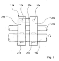
- FIG. 1 shows individual parts of a gas exchange valve actuating device of an internal combustion engine, which is intended to transmit a drive movement to gas exchange valves 10a, wherein only one gas exchange valve 10a is indicated.
- the gas exchange valve operating device comprises a camshaft 19a having an exhaust cam 20a and a brake cam 21a of an engine brake unit 11a.
- the exhaust cam 20a acts on a first end of a Auslrawkipphebels 22a, which is pivotally mounted on a rocker shaft 23a and acts with its second end to the provided as an outlet valve gas exchange valve 10a.
- the brake cam 21a is disposed on the camshaft 19a in the region of a brake rocker arm 24a of the engine brake unit 11a.
- the brake rocker arm 24a is also pivotally mounted on the rocker shaft 23a and is pivotable outside of a braking operation relative to the brake rocker arm 24a.
- the brake rocker arm 24a has, at its end facing the gas exchange valve 10a, a transverse arm 25a which is guided transversely to the brake rocker arm 24a or parallel to the rocker arm shaft 23a in the direction of the brake rocker arm 24a.
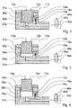
- an actuator unit is arranged with an actuator means 12a formed by a hydraulically actuated actuator piston (FIGS. 1 and 2).
- the actuator 12a is guided in a housing 26a of the actuator unit.
- the actuator unit has a hydraulically formed locking unit 13a, which is provided to actuate the actuator 12a from a certain position of the Actuator means 12a against a counter force 14a to lock.
- the locking unit 13a has a bypass 15a formed by a channel formed in the housing 26a, via which pressure medium can flow away up to the specific position of the actuator 12a.
- the actuator means 12a Before the braking operation is activated, the actuator means 12a is in its lower position due to the force acting on the actuator means 12a gravity or due to the force of a - not shown - spring.
- the gas exchange valve 10a is opened independently of the brake cam 21a by the exhaust cam 20a via the exhaust rocker arm 22a and closed by a valve spring (not shown) acting in the closing direction of the gas exchange valve 10a.
- a 2/2-way valve 45a is connected via a pressure build-up and pressure medium flows via a check valve 30a of the 2/2-way valve 45a and via an inlet channel 27a into a pressure chamber 28a below the actuator means 12a and the actuator 12a extends the housing 26a ( FIG. 3 ).
- the pressure limiting valve 16a is closed during the extension of the actuator means 12a without or without significant counterforce and opens when the actuator 12a at a pressure slightly above a maximum system pressure in the inlet channel 27a of the internal combustion engine or when the rocker arms 22a, 24a during the extension of the actuator means 12a are coupled. In principle, however, it is also conceivable that a bypass without corresponding pressure relief valve 16a is provided.
- the actuator means 12a is by means of Arretieraji 13a locked, namely by the bypass 15a is connected on both sides with the pressure chamber 28a and the bypass 15a connects the pressure chamber 28a with the inflow channel 27a and thereby prevented that can flow through the bypass 15a pressure fluid ( Figure 4).
- the actuator 12a comes with its guide collar 29a to a stop 31a to the plant.
- the inflow passage 27a and the bypass 15a are dimensioned such that at any pressure medium temperature or oil temperature possibly occurring during operation and any engine speed possibly occurring in operation, the actuator means 12a can be fully extended in one cycle reduced by an opening time of the gas exchange valve 10a ,
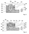
- FIGS. 5 to 8 Alternative embodiments are shown. Substantially identical components, features and functions are basically numbered by the same reference numerals. To distinguish the embodiments, however, the reference numerals of the embodiments, the letters a to e are added. The following description is essentially limited to the differences from the embodiment in the FIGS. 1 to 4 , wherein with respect to the same components, features and functions on the description of the embodiment in the FIGS. 1 to 4 can be referenced.
- FIG. 5 an alternative actuator unit is shown with a locking unit 13b having a partially arranged in an actuator means 12b by-pass 15b. Before the actuator 12b is fully extended, can flow through the bypass 15b pressure fluid from a pressure chamber 28b. When the actuator means 12b is fully extended, a passage portion 15b 'of the bypass 15b in a housing 26b of the actuator unit is via a guide collar 29b of the actuator means 12b and a passage portion 15b "of the bypass 15b closed by a stopper 31b to the outside and the actuator 12b is locked.
- FIG. 6 an alternative actuator unit is shown with a locking unit 13c having a partially arranged in an actuator 12c bypass 15c. Furthermore, the actuator unit has an energy storage unit 17c formed by a hydraulic pressure storage unit, which is intended to store energy during a compensating movement of the actuator means 12c.
- the energy storage unit 17c has a mechanical spring element 18c formed by a helical compression spring in an annular space 32c of a housing 26c of the actuator unit, which is supported at a first end on a component forming a stop 31c and at a second end on a spring retainer 33c.
- the spring plate 33c is secured in the direction away from the spring element 18c by a tensioning disc 34c and is displaceably guided in the direction of the spring element 18c counter to a spring force of the spring element 18c in the annular space 32c. In this case prevents a stop not shown in the stop 31c, that the spring element 18c goes to block.
- the actuator means 12c Before the braking operation is activated, the actuator means 12c is in its lower position due to gravity acting on the actuator means 12c or due to the force of a spring (not shown).
- pressure medium flows via an inlet channel 27c into a pressure chamber 28c below the actuator means 12c and the actuator means 12c extends out of the housing 26c ( FIG. 6 ).
- the actuator 12c is extended again particularly quickly to its position at which it stood before the coupling of the rocker arms. Until the next coupling of the rocker arms, the actuator 12c can be extended further. It can be a kind of iterative extension of the actuator 12c, in particular over several cycles, can be achieved.
- the actuator means 12c When the actuator means 12c is fully extended, the actuator means 12c is locked by means of the locking unit 13c, by closing a passage section 15c 'of the bypass 15c by means of a guide collar 29c of the actuator means 12c and a passage section 15c "of the bypass 15c via the stop 31c, so that an outflow of pressure medium from the pressure chamber 28c is prevented via the bypass 15c in the annular space 32c.
- the annular space 32c is connected via a channel 35c to a space adjacent to the actuator unit.
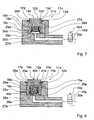
- FIG. 7 an alternative actuator unit is shown with a locking unit 13d having a partially arranged in an actuator means 12d bypass 15d. Furthermore, the actuator unit has one of a hydraulic pressure storage unit formed energy storage unit 17d, which is intended to store energy during a compensating movement of the actuator 12d.
- the energy storage unit 17d has within the actuator means 12d in a spring chamber 36d a mechanical spring element 18d formed by a helical compression spring, which is supported at a first end on a lower side of the actuator means and at a second end on a spring plate 33d.
- the spring plate 33d is secured in the direction away from the spring element 18d by a clamping disk 34d in the actuator means 12d and is guided in the direction of the spring element 18d, against a spring force of the spring element 18d, displaceable in the actuator 12d. In this case, prevents a stop not shown in the actuator 12d that the spring element 18d goes to block.
- the actuator means 12d Before the braking operation is activated, the actuator means 12d is in its lower position due to gravity acting on the actuator means 12d or due to the force of a spring (not shown).
- pressure medium flows via an inlet channel 27d into a pressure chamber 28d below the actuator means 12d or underneath the spring plate 33d and the actuator means 12d extends out of the housing 26d ( FIG. 7 ).
- the actuator means 12d is locked by means of the locking unit 13d, namely by the bypass 15d or the channel section 15d '' 'being closed by means of a guide collar 29d of the actuator means 12d, so that an outflow of pressure medium from the spring chamber 36d over the bypass 15d is avoided. Furthermore, when the actuator means 12d is fully extended, the spring chamber 36d is connected to the inflow channel 27d via a channel 37d, so that air still remaining from the spring chamber 36d is pressed during operation by a pumping effect, the spring chamber 36d is completely filled with hydraulic pressure medium from the inflow channel 27d and Actuator 12d can be locked by hydraulic pressure medium.
- FIG. 8 an alternative actuator unit is shown with a locking unit 13e having a bypass 15e. Furthermore, the actuator unit has an energy storage unit 17e formed by a hydraulic pressure storage unit, which is provided to store energy during a compensation movement of an actuator means 12e.
- the energy storage unit 17e has within the actuator means 12e in a spring chamber 36e one formed by a helical compression spring mechanical spring element 18e, which is supported on a first, a support surface of the actuator means 12e for a rocker arm end facing a mounted in the actuator means 12e spring plate 33e and at a second end to a fixed in the actuator 12e lid 38e.
- the spring plate 33e is secured in the direction away from the spring element 18e by a shoulder 39e of the actuator means 12e and is displaceably guided in the direction of the spring element 18e against a spring force of the spring element 18e in the actuator 12e. In this case, prevents a non-illustrated stop in the lid 38e, that the spring element 18e goes to block.
- the actuator means 12e Before the braking operation is activated, the actuator means 12e is in its lower position due to gravity acting on the actuator means 12e or due to the force of a spring (not shown).
- pressure medium flows via an inlet channel 27e into a pressure chamber 28e below the actuator means 12e or below the lid 38e and the actuator means 12e extends out of a housing 26e ( FIG. 8 ).
- the actuator means 12e can be extended further.
- the spring chamber 36e is connected via a channel 41e, an annular space 42e and via a channel 43e to a space adjoining the actuator unit.
- the actuator 12e is locked by means of the locking unit 13e, namely by the bypass 15e is closed by means of a guide collar 29e of the actuator 12e, so that an outflow of pressure fluid from the pressure chamber 28e via the bypass 15e in the pressure chamber 40e is avoided in the actuator 12e. Furthermore, the channel 43e is closed by a guide collar 44e of the actuator means 12e.
Landscapes
- Engineering & Computer Science (AREA)
- Mechanical Engineering (AREA)
- General Engineering & Computer Science (AREA)
- Valve Device For Special Equipments (AREA)
- Actuator (AREA)
- Fluid-Pressure Circuits (AREA)
Applications Claiming Priority (2)
| Application Number | Priority Date | Filing Date | Title |
|---|---|---|---|
| DE102006015893A DE102006015893A1 (de) | 2006-04-05 | 2006-04-05 | Gaswechselventilbetätigungsvorrichtung |
| PCT/EP2007/002932 WO2007115715A1 (de) | 2006-04-05 | 2007-04-02 | Gaswechselventilbetätigungsvorrichtung |
Publications (2)
| Publication Number | Publication Date |
|---|---|
| EP2002090A1 EP2002090A1 (de) | 2008-12-17 |
| EP2002090B1 true EP2002090B1 (de) | 2010-12-29 |
Family
ID=38426482
Family Applications (1)
| Application Number | Title | Priority Date | Filing Date |
|---|---|---|---|
| EP07723873A Not-in-force EP2002090B1 (de) | 2006-04-05 | 2007-04-02 | Gaswechselventilbetätigungsvorrichtung |
Country Status (6)
| Country | Link |
|---|---|
| US (1) | US8056533B2 (https=) |
| EP (1) | EP2002090B1 (https=) |
| JP (1) | JP4988820B2 (https=) |
| CN (1) | CN101415912B (https=) |
| DE (2) | DE102006015893A1 (https=) |
| WO (1) | WO2007115715A1 (https=) |
Families Citing this family (8)
| Publication number | Priority date | Publication date | Assignee | Title |
|---|---|---|---|---|
| DE102008052037B3 (de) * | 2008-10-16 | 2010-04-08 | Moeller Gmbh | Solarmodul |
| KR101047658B1 (ko) * | 2009-07-31 | 2011-07-07 | 기아자동차주식회사 | 엔진브레이크 모듈 |
| KR101057894B1 (ko) * | 2009-09-22 | 2011-08-22 | 기아자동차주식회사 | 차량의 엔진브레이크 장치 |
| KR101143559B1 (ko) * | 2009-09-25 | 2012-05-24 | 기아자동차주식회사 | 오일유로 통합형 엔진브레이크 장치 |
| US9335045B2 (en) | 2010-01-15 | 2016-05-10 | Lennox Industries Inc. | Furnace, a method for operating a furnace and a furnace controller configured for the same |
| US9770792B2 (en) | 2010-01-15 | 2017-09-26 | Lennox Industries Inc. | Heat exchanger having an interference rib |
| KR101209738B1 (ko) * | 2010-08-31 | 2012-12-07 | 기아자동차주식회사 | 로커암 일체형 가변 밸브 액츄에이터 |
| WO2018034749A1 (en) * | 2016-08-19 | 2018-02-22 | Pacbrake Company | Compression-release engine brake system for lost motion rocker arm assembly and method of operation thereof |
Family Cites Families (18)
| Publication number | Priority date | Publication date | Assignee | Title |
|---|---|---|---|---|
| NL54042C (https=) * | 1937-10-26 | |||
| DE4025569C1 (en) * | 1990-08-11 | 1991-07-18 | Mercedes-Benz Aktiengesellschaft, 7000 Stuttgart, De | Valve brake for vehicle IC engine - has separately controllable cylinder outlet valves for drive and braking functions |
| US5195489A (en) * | 1992-01-03 | 1993-03-23 | Jacobs Brake Technology Corporation | Push rods for pistons in compression release engine retarders |
| SE470363B (sv) * | 1992-06-17 | 1994-01-31 | Volvo Ab | Förfarande och anordning för motorbromsning med en flercylindrig förbränningsmotor |
| SE501193C2 (sv) * | 1993-04-27 | 1994-12-05 | Volvo Ab | Avgasventilmekanism i en förbränningsmotor |
| SE504145C2 (sv) * | 1995-03-20 | 1996-11-18 | Volvo Ab | Avgasventilmekanism i en förbränningsmotor |
| US5975251A (en) * | 1998-04-01 | 1999-11-02 | Diesel Engine Retarders, Inc. | Rocker brake assembly with hydraulic lock |
| JP3764595B2 (ja) * | 1998-12-24 | 2006-04-12 | 株式会社日立製作所 | エンジン補助ブレーキ装置 |
| WO2001020150A1 (en) * | 1999-09-17 | 2001-03-22 | Diesel Engine Retarders, Inc. | Captive volume accumulator for a lost motion system |
| DE60045108D1 (de) * | 1999-12-20 | 2010-11-25 | Jacobs Vehicle Systems Inc | Verfahren und vorrichtung zum hydraulischen an- und loskoppeln einer motorbremse mittels totgang |
| US6691674B2 (en) * | 2001-06-13 | 2004-02-17 | Diesel Engine Retarders, Inc. | Latched reset mechanism for engine brake |
| DE10143959A1 (de) * | 2001-09-07 | 2003-03-27 | Bosch Gmbh Robert | Hydraulisch gesteuerter Aktuator zur Betätigung eines Ventils |
| SE523849C2 (sv) * | 2001-10-11 | 2004-05-25 | Volvo Lastvagnar Ab | Avgasventilmekanism i förbränningsmotor |
| US7140333B2 (en) * | 2002-11-12 | 2006-11-28 | Volvo Lastvagnar Ab | Apparatus for an internal combustion engine |
| JP2004183515A (ja) * | 2002-11-29 | 2004-07-02 | Nippon Piston Ring Co Ltd | バルブメカニズム |
| SE526636C2 (sv) * | 2004-02-23 | 2005-10-18 | Volvo Lastvagnar Ab | Avgasventilmekanism för en förbränningsmotor |
| WO2005107418A2 (en) * | 2004-05-06 | 2005-11-17 | Jacobs Vehicle Systems, Inc. | Primary and offset actuator rocker arms for engine valve actuation |
| WO2006004591A2 (en) * | 2004-05-14 | 2006-01-12 | Jacobs Vehicle Systems, Inc. | Rocker arm system for engine valve actuation |
-
2006
- 2006-04-05 DE DE102006015893A patent/DE102006015893A1/de not_active Withdrawn
-
2007
- 2007-04-02 CN CN2007800120552A patent/CN101415912B/zh not_active Expired - Fee Related
- 2007-04-02 WO PCT/EP2007/002932 patent/WO2007115715A1/de not_active Ceased
- 2007-04-02 EP EP07723873A patent/EP2002090B1/de not_active Not-in-force
- 2007-04-02 DE DE502007006107T patent/DE502007006107D1/de active Active
- 2007-04-02 JP JP2009503468A patent/JP4988820B2/ja not_active Expired - Fee Related
-
2008
- 2008-09-29 US US12/286,436 patent/US8056533B2/en not_active Expired - Fee Related
Also Published As
| Publication number | Publication date |
|---|---|
| CN101415912A (zh) | 2009-04-22 |
| JP4988820B2 (ja) | 2012-08-01 |
| CN101415912B (zh) | 2012-02-29 |
| EP2002090A1 (de) | 2008-12-17 |
| DE502007006107D1 (de) | 2011-02-10 |
| US8056533B2 (en) | 2011-11-15 |
| JP2009532640A (ja) | 2009-09-10 |
| DE102006015893A1 (de) | 2007-10-11 |
| WO2007115715A1 (de) | 2007-10-18 |
| US20090139486A1 (en) | 2009-06-04 |
Similar Documents
| Publication | Publication Date | Title |
|---|---|---|
| EP2002090B1 (de) | Gaswechselventilbetätigungsvorrichtung | |
| AT510529B1 (de) | Viertakt-brennkraftmaschine mit einer motorbremse | |
| EP2129881B1 (de) | Hubkolbenbrennkraftmaschine mit motorbremseinrichtung | |
| DE19908286B4 (de) | Variable Ventilsteuerung für Brennkraftmaschinen | |
| WO2015051794A1 (de) | Hydraulische ventilsteuerung einer brennkraftmaschine | |
| WO2004033860A1 (de) | Verriegelungseinrichtung für einen nockenwellenversteller | |
| DE19801603A1 (de) | Auf unterschiedliche Hübe für wenigstens ein Gaswechselventil schaltbarer Nockenfolger eines Ventiltriebs einer Brennkraftmaschine | |
| AT521606B1 (de) | Hydraulischer Ventilmechanismus für längenverstellbare Pleuelstange | |
| DE60310743T2 (de) | Vorrichtung zum ventilausschalten einer brennkraftmaschine | |
| EP2789853B1 (de) | Vorrichtung zum Fördern von Druckluft für druckluftbetriebene Einrichtungen in Kraftfahrzeugen | |
| DE10223409A1 (de) | Nockenwellenversteller | |
| DE102019008969B4 (de) | Ventilbetätigungseinrichtung für eine Verbrennungskraftmaschine sowie Verfahren zum Betreiben einer solchen Ventilbetätigungseinrichtung | |
| AT521269B1 (de) | Hydraulisches Steuerventil für eine längenverstellbare Pleuelstange mit zwei Steuerdruckräumen | |
| DE3935218A1 (de) | Hydraulische ventilsteuerung fuer brennkraftmaschinen | |
| DE102016213976A1 (de) | Elektrohydraulischer Ventiltrieb eines Verbrennungsmotors | |
| DE102013017882A1 (de) | Ventiltriebvorrichtung mit veränderbarem Stellbereich | |
| DE112005002543B4 (de) | Brennkraftmaschine und ein Verfahren zum Betreiben einer Brennkraftmaschine | |
| DE102008027163A1 (de) | Ventilspielausgleichsvorrichtung | |
| DE102005021113A1 (de) | Gaswechselventilbetätigungsvorrichtung | |
| DE20122600U1 (de) | Variabler Ventiltrieb für ein nockenbetätigtes Hubventil einer Brennkraftmaschine | |
| DE19956584C2 (de) | Desmodromische Vorrichtung zur Betätigung eines Gaswechselventils einer Brennkraftmaschine | |
| DE102004029750A1 (de) | Nocken zur Beaufschlagung eines Ventiltriebs einer Brennkraftmaschine | |
| AT519300B1 (de) | Längenverstellbare Pleuelstange mit Zylinder-Kolben-Einheit mit Spaltdichtung und dehnbarem Kolbenkragen | |
| DE102012105524A1 (de) | Nockenwellenversteller | |
| AT521268A4 (de) | Längenverstellbare Pleuelstange mit hydraulischer Steuereinrichtung |
Legal Events
| Date | Code | Title | Description |
|---|---|---|---|
| PUAI | Public reference made under article 153(3) epc to a published international application that has entered the european phase |
Free format text: ORIGINAL CODE: 0009012 |
|
| 17P | Request for examination filed |
Effective date: 20080903 |
|
| AK | Designated contracting states |
Kind code of ref document: A1 Designated state(s): DE FR GB IT SE |
|
| DAX | Request for extension of the european patent (deleted) | ||
| RBV | Designated contracting states (corrected) |
Designated state(s): DE FR GB IT SE |
|
| 17Q | First examination report despatched |
Effective date: 20090729 |
|
| GRAP | Despatch of communication of intention to grant a patent |
Free format text: ORIGINAL CODE: EPIDOSNIGR1 |
|
| GRAC | Information related to communication of intention to grant a patent modified |
Free format text: ORIGINAL CODE: EPIDOSCIGR1 |
|
| GRAC | Information related to communication of intention to grant a patent modified |
Free format text: ORIGINAL CODE: EPIDOSCIGR1 |
|
| GRAS | Grant fee paid |
Free format text: ORIGINAL CODE: EPIDOSNIGR3 |
|
| GRAA | (expected) grant |
Free format text: ORIGINAL CODE: 0009210 |
|
| RAP1 | Party data changed (applicant data changed or rights of an application transferred) |
Owner name: DAIMLER AG |
|
| AK | Designated contracting states |
Kind code of ref document: B1 Designated state(s): DE FR GB IT SE |
|
| REG | Reference to a national code |
Ref country code: GB Ref legal event code: FG4D Free format text: NOT ENGLISH |
|
| REF | Corresponds to: |
Ref document number: 502007006107 Country of ref document: DE Date of ref document: 20110210 Kind code of ref document: P |
|
| REG | Reference to a national code |
Ref country code: DE Ref legal event code: R096 Ref document number: 502007006107 Country of ref document: DE Effective date: 20110210 |
|
| REG | Reference to a national code |
Ref country code: SE Ref legal event code: TRGR |
|
| PLBE | No opposition filed within time limit |
Free format text: ORIGINAL CODE: 0009261 |
|
| STAA | Information on the status of an ep patent application or granted ep patent |
Free format text: STATUS: NO OPPOSITION FILED WITHIN TIME LIMIT |
|
| 26N | No opposition filed |
Effective date: 20110930 |
|
| REG | Reference to a national code |
Ref country code: DE Ref legal event code: R097 Ref document number: 502007006107 Country of ref document: DE Effective date: 20110930 |
|
| PG25 | Lapsed in a contracting state [announced via postgrant information from national office to epo] |
Ref country code: IT Free format text: LAPSE BECAUSE OF FAILURE TO SUBMIT A TRANSLATION OF THE DESCRIPTION OR TO PAY THE FEE WITHIN THE PRESCRIBED TIME-LIMIT Effective date: 20101229 |
|
| REG | Reference to a national code |
Ref country code: FR Ref legal event code: PLFP Year of fee payment: 9 |
|
| PGFP | Annual fee paid to national office [announced via postgrant information from national office to epo] |
Ref country code: GB Payment date: 20150430 Year of fee payment: 9 Ref country code: SE Payment date: 20150429 Year of fee payment: 9 |
|
| PGFP | Annual fee paid to national office [announced via postgrant information from national office to epo] |
Ref country code: FR Payment date: 20150430 Year of fee payment: 9 |
|
| PGFP | Annual fee paid to national office [announced via postgrant information from national office to epo] |
Ref country code: DE Payment date: 20150630 Year of fee payment: 9 |
|
| REG | Reference to a national code |
Ref country code: DE Ref legal event code: R119 Ref document number: 502007006107 Country of ref document: DE |
|
| REG | Reference to a national code |
Ref country code: SE Ref legal event code: EUG |
|
| GBPC | Gb: european patent ceased through non-payment of renewal fee |
Effective date: 20160402 |
|
| REG | Reference to a national code |
Ref country code: FR Ref legal event code: ST Effective date: 20161230 |
|
| PG25 | Lapsed in a contracting state [announced via postgrant information from national office to epo] |
Ref country code: GB Free format text: LAPSE BECAUSE OF NON-PAYMENT OF DUE FEES Effective date: 20160402 Ref country code: FR Free format text: LAPSE BECAUSE OF NON-PAYMENT OF DUE FEES Effective date: 20160502 Ref country code: DE Free format text: LAPSE BECAUSE OF NON-PAYMENT OF DUE FEES Effective date: 20161101 |
|
| PG25 | Lapsed in a contracting state [announced via postgrant information from national office to epo] |
Ref country code: SE Free format text: LAPSE BECAUSE OF NON-PAYMENT OF DUE FEES Effective date: 20160403 |