EP2001095A2 - Buchse für Generator - Google Patents
Buchse für Generator Download PDFInfo
- Publication number
- EP2001095A2 EP2001095A2 EP08010203A EP08010203A EP2001095A2 EP 2001095 A2 EP2001095 A2 EP 2001095A2 EP 08010203 A EP08010203 A EP 08010203A EP 08010203 A EP08010203 A EP 08010203A EP 2001095 A2 EP2001095 A2 EP 2001095A2
- Authority
- EP
- European Patent Office
- Prior art keywords
- terminal
- cooling gas
- bushing
- inner corner
- bend
- Prior art date
- Legal status (The legal status is an assumption and is not a legal conclusion. Google has not performed a legal analysis and makes no representation as to the accuracy of the status listed.)
- Granted
Links
Images


Classifications
-
- H—ELECTRICITY
- H02—GENERATION; CONVERSION OR DISTRIBUTION OF ELECTRIC POWER
- H02G—INSTALLATION OF ELECTRIC CABLES OR LINES, OR OF COMBINED OPTICAL AND ELECTRIC CABLES OR LINES
- H02G15/00—Cable fittings
- H02G15/20—Cable fittings for cables filled with or surrounded by gas or oil
- H02G15/22—Cable terminations
-
- H—ELECTRICITY
- H02—GENERATION; CONVERSION OR DISTRIBUTION OF ELECTRIC POWER
- H02G—INSTALLATION OF ELECTRIC CABLES OR LINES, OR OF COMBINED OPTICAL AND ELECTRIC CABLES OR LINES
- H02G15/00—Cable fittings
- H02G15/20—Cable fittings for cables filled with or surrounded by gas or oil
- H02G15/32—Cable inlets
Definitions
- the present invention relates to a bushing, particularly a bushing which allows electric current and cooling gas to flow through a containment vessel to a generator main unit placed in the containment vessel, and a generator with this bushing.
- the bushing according to the present invention can be applied to many types of electric equipment for large currents, such as generators used in electric power stations and transformers or condensers used in transforming stations.
- the bushing should be easy to assemble, easy to service, and be able to absorb expansion or contraction with temperature change of peripheral devices around the bushing. Also the bushing and the devices around it should be compact. For this reason, the structure around the bushing is complicated and the total of electric contact resistances between components in the peripheral devices is large; for example, if currents of tens of kiloamperes flow, joule heat of tens of kilowatts is generated.
- the bushing is designed to flow the cooling gas such as hydrogen gas through it and cool itself down.
- a bushing including a conductive conduit tube, a conductive lead tube and a terminal for connecting the conduit tube and the lead tube
- the inner corner of the bend tends to be higher in temperature than other parts. If the temperature of the inner corner of the bend is kept low, it enables a larger current to flow without increasing the sizes of the bushing, the devices around it, and the generator itself.
- JP-A HEI 10-283860 no means to improve the cooling effect at the bend is described for a bushing which has a terminal with a bend.
- An object of the present invention is to provide a bushing which is, for a terminal with a bend, designed to improve the effect to cool the inner corner of the bend, and to provide a generator including the same.
- a bushing includes a conductive conduit tube, a conductive lead tube, and a terminal for connecting the conduit tube and the lead tube.
- the terminal has a bend and electric current flows in the conduit tube, the terminal, and the lead tube.
- Cooling gas flows in the conduit tube, the terminal, and the lead tube, and a cooling means is provided for forced cooling of the inner corner of the bend of the terminal.
- a generator includes a generator main unit, a containment vessel to place the generator main unit in a cooling gas atmosphere, a bushing which penetrates the containment vessel and enables electric current to flow through the containment vessel, and a blower and a gas cooler which feed cooling gas into the containment vessel and the bushing.
- the bushing includes a conduit tube, a lead tube to be connected with the generator main unit, and a terminal which connects the conduit tube and the lead tube.
- the terminal has a bend and a cooling means is provided for forced cooling of the inner corner of the bend of the terminal.
- a guide be provided in the terminal to concentrate the cooling gas flowing in the terminal on the inner corner of the bend. It is also preferable that a radiating fin be provided on an inner or outer surface of the inner corner of the bend of the terminal. It is also preferable that a mechanism be provided to make the cooling gas hit outside of the inner corner of the terminal. It is possible to use a combination of these means.
- a larger current can flow through the bushing than that in conventional cooling structures, even if the bushing size is unchanged. This means that a larger current can flow without increasing the sizes of the bushing, devices around the bushing, and generator itself.
- Fig. 12 shows a structure of a general bushing for large currents and devices around it.
- the bushing includes a conduit tube 5 through which current flows, an inside lead tube 2 which leads electric power from the generator main unit 13 or a motor into the conduit tube 5, an inside terminal 4 which connects the conduit tube 5 and the inside lead tube 2 inside the containment vessel 9, an outside lead tube 12 which feeds electric power to a station load or power system outside the containment vessel 9, and an outside terminal 10 which connects the conduit tube 5 and the outside lead tube 12 outside the containment vessel 9.
- It also includes an insulation member 6 and an insulation member holder 8 which fix and isolate the conduit tube 5 in the containment vessel 9.
- a cooling mechanism for the bushing is so structured that cooling gas 1, such as hydrogen gas, cooled by a cooler 16 is circulated through a blower duct 18 made of insulation material, a ventilation hole 7 in the insulation member 6, the conduit tube 5, the inside terminal 4 and the inside lead tube 2 with a blower17.
- a plug 11 is provided at the bottom of the conduit tube 5 to prevent the cooling gas 1 from flowing out of the containment vessel 9.
- the inside terminal 4 is bent for convenience in layout, covered by an insulation member for thermally insulation.
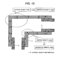
- Fig. 13 shows a current distribution in the vertical section of the inside terminal 4 which electromagnetic field analysis revealed.
- the current is found to concentrate on the periphery of the inner corner of the inside terminal 4 where it is bent. This is because current has a tendency to concentrate in a shorter route and, in the case of alternating current, concentrate on the periphery of the route (conductor) due to a conductor skin effect.
- joule heat generation density is in proportion to the square of current density, joule heat concentrates on the periphery of the inner corner of the inside terminal 4 as well as in the case of current.
- Fig. 14 shows a flow velocity distribution of the cooling gas 1 in the vertical section of the inside terminal 4 which thermal hydraulics analysis has revealed.
- the cooling gas 1 is found to flow through the bent terminal while concentrating on the outer corner side in the latter half of the bend, namely on the downstream side close to the bend. The reason is that the direction of the gas flow cannot change immediately at the bend because of the gas's inertia.
- the coefficient of heat transfer between the cooling gas 1 and the wall of the terminal 4 is almost proportional to the flow velocity of the cooling gas 1. Therefore, the cooling efficiency is higher at the outer corner side than at the inner corner side.
- Fig. 15 shows a temperature distribution in the vertical section of the inside terminal 4 which thermal hydraulics analysis has revealed. As shown in Fig. 15 , it is found that, in the outer corner (periphery side) of the bend of the inside terminal 4, less Joule heat is generated, cooling efficiency is high and thus the temperatures are low, while, in its inner corner, more heat is generated, cooling efficiency is low and therefore the temperatures are high.
- the maximum temperature is a constrained condition in bushing design.
- Fig. 16 is an assembly drawing of the inside terminal 4 of the comparative example 1.
- the inside terminal 4 electric contact resistance needs to be decreased between the inside terminal 4 and the conduit tube 5 or the inside lead tube 2 in order to reduce joule heat generation and prevent temperature increase at the areas where the inside terminal 4 contacts them.
- the inside terminal 4 has a split structure, namely it consists of two parts as shown in Fig. 16 , and these two parts are joined by fastening with bolts or the like so that the parts come into close contact with each other with increased pressure between them.
- Fig. 17 shows another example of an inside terminal. This inside terminal can be divided into two fractions along the broken line.
- Fig. 18 also shows another example of an inside terminal. This inside terminal can be divided into three fractions along the broken line.
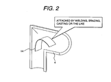
- Fig. 2 shows a structure of an inside terminal 4 with a guide vane 14 in it.
- the guide vane 14 is installed in the inside terminal 4 which has the same structure as in the comparative example 1 except for the guide vane 14.
- the guide vane 14 can be attached by welding, alloy brazing, casting or the like since the inside terminal 4 has a split structure.
- Fig. 1 shows a cooling gas flow velocity distribution in the vertical section of the inside terminal 4 with the guide vane 14 installed in it, which thermal hydraulics analysis has revealed.
- the guide vane 14 causes the inflowing cooling gas 1 from the conduit tube 5 to concentrate around the inner corner of the inside terminal 4 and flow at higher velocity. Consequently, the heat generated at the inner corner of the inside terminal 4 is efficiently removed and the temperature of the inner corner area is decreased. As the temperature decreases, the terminal's electric resistance becomes smaller and heat generation is reduced, resulting in further lowering of the temperature.
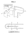
- Fig. 3 shows a method of installing the guide vane 14.
- the guide vane 14 is attached to a guide vane holder 15 in addition to the same terminal 4 as in the comparative example 1.
- the guide vane 14 and the guide vane holder 15 are sandwiched and fixed between the constituent parts of the inside terminal 4. Consequently, the same effect can be achieved as in the first embodiment.
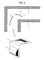
- Fig. 4 shows another structure of installing the guide vane 14.
- the guide vane 14 is formed in an L-shaped guide vane holder 15 by cutting and bending a plate for the holder 15 in addition to the same terminal 4 as in the comparative example 2.
- the guide vane 14 and the guide vane holder 15 are sandwiched and fixed between the constituent parts of the inside terminal 4. Consequently, the same effect can be achieved as in the first and second embodiments.
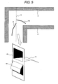
- Fig. 5 also shows another structure of installing the guide vane 14.
- the guide vane 14 is formed in a flat-shaped guide vane holder 15 by cutting and bending a plate for the holder 15 in addition to the same terminal 4 as in the comparative example 3.
- the guide vane 14 and the guide vane holder 15 are sandwiched and fixed between the constituent parts of the inside terminal 4. Consequently, the same effect can be achieved as in the first to third embodiments.
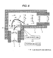
- Fig. 6 shows a structure of installing an auxiliary guide vane 21 in addition to the guide vane 14.
- an auxiliary guide vane 21 is installed nearer to the inner corner than the guide vane 14 as shown in Fig. 6 so that the cooling gas 1 hits the upstream side of the inner corner of the inside terminal 4. Consequently the temperatures are decreased more than in the first to fourth embodiments.
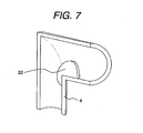
- Fig. 7 shows a structure of installing a radiating fin 20.
- the cooling gas 1 hits the inner surface of the inner corner of the inside terminal 4.
- Mounting one or more radiating fins 20 on the inner corner of the inside terminal 4 as shown in Fig. 7 makes heat transfer area wider and therefore enables further decrease of the temperatures of the inner corner and its neighborhood.
- Fig. 8 shows a structure of the bushing and devices around it in the seventh embodiment.
- the present embodiment's structure has a similar cooling gas-circulating system to that of the comparative example 1.
- the circulating system comprises the blower duct 18, the ventilation hole 7, the conduit tube 5, the inside terminal 4, the inside lead tube 2 and the blower 17.
- the downstream side of the blower duct 18 from the blower 17 is extended up to the immediate vicinity of the periphery of the inner corner of the inside terminal 4.
- the cooling gas 1 to be sent from the blower 17 to the bushing etc. is led to the inside terminal 4 through the circulating system, and the cooling gas 1 issued from an outlet of the blower duct 18 hits the outer surface of the inner corner of the inside terminal 4. Consequently the corner is cooled and the temperature increase is reduced.
- Fig. 9 shows a structure of the bushing and the devices around it in the eighth embodiment. Also the present embodiment's structure has a similar cooling gas-circulating system to that of the comparative example 1.
- a different technical point is as follows.
- An inside terminal cover 19 made of insulating material is attached so that it covers the inside terminal 4.
- the inside terminal cover 19 has a duct 3.
- An outlet of the duct 3 is positioned in the vicinity of the periphery of the inner corner of the inside terminal 4. Therefore, the cooling gas 1, which is sent from the blower 17 into the containment vessel 9, passes through the duct 3 of the inside terminal cover 19 to flow into the bushing. In this process, the cooling gas 1 hits the outer surface of the inner corner of the inside terminal 4 where much heat is generated. Consequently the corner is cooled and the temperature increase is reduced.
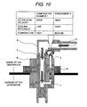
- Fig. 10 shows another example of a structure of the bushing and the devices around it in the ninth embodiment.
- the flow direction of the cooling gas 1 is reverse to that in the comparative examples 1 to 3 and the first to eighth embodiments.
- a duct 3 is attached to an outlet of the ventilation hole 7 so as to be directed to the periphery of the inner corner of the inside terminal 4.
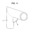
- Fig. 11 shows a structure of attaching a radiating fin 20.
- the cooling gas 1 hits the outer surface of the inner corner of the inside terminal 4. Attaching one or more radiating fins 20 on the inner corner of the inside terminal 4 as shown in Fig. 11 makes heat transfer area wider and therefore enables further decrease of the temperatures of the inner corner and its neighborhood.
Landscapes
- Motor Or Generator Frames (AREA)
- Motor Or Generator Cooling System (AREA)
- Insulators (AREA)
Applications Claiming Priority (1)
| Application Number | Priority Date | Filing Date | Title |
|---|---|---|---|
| JP2007148119A JP4459982B2 (ja) | 2007-06-04 | 2007-06-04 | ブッシング及び発電機 |
Publications (3)
| Publication Number | Publication Date |
|---|---|
| EP2001095A2 true EP2001095A2 (de) | 2008-12-10 |
| EP2001095A3 EP2001095A3 (de) | 2011-10-26 |
| EP2001095B1 EP2001095B1 (de) | 2014-05-14 |
Family
ID=39765051
Family Applications (1)
| Application Number | Title | Priority Date | Filing Date |
|---|---|---|---|
| EP08010203.1A Ceased EP2001095B1 (de) | 2007-06-04 | 2008-06-04 | Buchse für Generator |
Country Status (3)
| Country | Link |
|---|---|
| US (1) | US20080296986A1 (de) |
| EP (1) | EP2001095B1 (de) |
| JP (1) | JP4459982B2 (de) |
Cited By (1)
| Publication number | Priority date | Publication date | Assignee | Title |
|---|---|---|---|---|
| EP2317630A1 (de) * | 2009-11-03 | 2011-05-04 | Alstom Technology Ltd | Kühlsystem für die Durchführungen eines elektrischen Generators und dazu korrespondierende Methode |
Families Citing this family (3)
| Publication number | Priority date | Publication date | Assignee | Title |
|---|---|---|---|---|
| JP5306037B2 (ja) * | 2009-04-23 | 2013-10-02 | 株式会社東芝 | 回転電機の高圧ブッシング |
| US9673606B2 (en) * | 2012-06-15 | 2017-06-06 | Flex-Cable | Pressurized electromechanical cable |
| CN112820487A (zh) * | 2020-07-31 | 2021-05-18 | 北京七一八友晟电子有限公司 | 一种大功率型水冷线绕固定电阻器 |
Citations (1)
| Publication number | Priority date | Publication date | Assignee | Title |
|---|---|---|---|---|
| JPH10283860A (ja) | 1997-04-01 | 1998-10-23 | Toshiba Corp | ブッシング |
Family Cites Families (4)
| Publication number | Priority date | Publication date | Assignee | Title |
|---|---|---|---|---|
| US2742582A (en) * | 1953-07-21 | 1956-04-17 | Gen Electric | Gas-cooled high voltage bushing for large generator |
| DE1020724B (de) * | 1954-05-20 | 1957-12-12 | Allis Chalmers Mfg Co | Gasgekuehlte dynamoelektrische Maschine |
| US2828428A (en) * | 1955-02-17 | 1958-03-25 | Westinghouse Electric Corp | Conductor-ventilated generators |
| US5374866A (en) * | 1993-07-21 | 1994-12-20 | General Electric Co. | Active cooling system for generator terminal box |
-
2007
- 2007-06-04 JP JP2007148119A patent/JP4459982B2/ja not_active Expired - Fee Related
-
2008
- 2008-06-02 US US12/131,411 patent/US20080296986A1/en not_active Abandoned
- 2008-06-04 EP EP08010203.1A patent/EP2001095B1/de not_active Ceased
Patent Citations (1)
| Publication number | Priority date | Publication date | Assignee | Title |
|---|---|---|---|---|
| JPH10283860A (ja) | 1997-04-01 | 1998-10-23 | Toshiba Corp | ブッシング |
Cited By (3)
| Publication number | Priority date | Publication date | Assignee | Title |
|---|---|---|---|---|
| EP2317630A1 (de) * | 2009-11-03 | 2011-05-04 | Alstom Technology Ltd | Kühlsystem für die Durchführungen eines elektrischen Generators und dazu korrespondierende Methode |
| WO2011054750A1 (en) * | 2009-11-03 | 2011-05-12 | Alstom Technology Ltd | Cooling system for the bushings of an electric generator and method for cooling the bushings of an electric generator |
| US8853897B2 (en) | 2009-11-03 | 2014-10-07 | Alstom Technology Ltd | Cooling system for the bushings of an electric generator and method for cooling the bushings of an electric generator |
Also Published As
| Publication number | Publication date |
|---|---|
| US20080296986A1 (en) | 2008-12-04 |
| JP2008301676A (ja) | 2008-12-11 |
| EP2001095A3 (de) | 2011-10-26 |
| EP2001095B1 (de) | 2014-05-14 |
| JP4459982B2 (ja) | 2010-04-28 |
Similar Documents
| Publication | Publication Date | Title |
|---|---|---|
| EP0356991B1 (de) | Wechselrichtervorrichtung | |
| EP2001095B1 (de) | Buchse für Generator | |
| EP4000992A1 (de) | Fahrzeugladestation | |
| JP4756012B2 (ja) | 配電装置 | |
| US20230052681A1 (en) | Charger Plug Nozzle | |
| CN217445577U (zh) | 一种油冷散热电源线路板 | |
| JP6827552B2 (ja) | 熱交換器ユニット及び空気調和装置 | |
| JP2024527789A (ja) | 半導体冷却装置付きコネクタ及び自動車 | |
| JP5620032B1 (ja) | 冷却装置 | |
| CN115885590A (zh) | 电气设备以及用于冷却电气设备的方法 | |
| EP3745833B1 (de) | Leistungselektronikeinheit für flugzeug und verfahren zur kühlung | |
| CN105051853A (zh) | 用于中压开关设备组件的气体冷却器 | |
| US20230182593A1 (en) | EV Charging Connector and EV Charging Station | |
| CN115715075A (zh) | 浸没冷却箱和浸没冷却变流器 | |
| CN212412580U (zh) | 一种电气工程控制柜 | |
| JP6961047B1 (ja) | 電力変換装置 | |
| JP2002324990A (ja) | 電力系統リレー装置 | |
| JP2020188622A (ja) | 電力変換装置 | |
| CN218006875U (zh) | 一种车载电子设备的散热结构 | |
| CN220061963U (zh) | 电控装置及制冷设备 | |
| KR100255175B1 (ko) | 전기자동차의 냉각장치 | |
| KR102667110B1 (ko) | 곡관 냉각장치 | |
| CN217336240U (zh) | 一种散热结构及包括该散热结构的单包逆变器 | |
| CN214312871U (zh) | 一种便于散热的智能化电力变压器 | |
| CN218101161U (zh) | 一种适用于大功率风冷行波管的散热结构 |
Legal Events
| Date | Code | Title | Description |
|---|---|---|---|
| PUAI | Public reference made under article 153(3) epc to a published international application that has entered the european phase |
Free format text: ORIGINAL CODE: 0009012 |
|
| AK | Designated contracting states |
Kind code of ref document: A2 Designated state(s): AT BE BG CH CY CZ DE DK EE ES FI FR GB GR HR HU IE IS IT LI LT LU LV MC MT NL NO PL PT RO SE SI SK TR |
|
| AX | Request for extension of the european patent |
Extension state: AL BA MK RS |
|
| 17P | Request for examination filed |
Effective date: 20100331 |
|
| PUAL | Search report despatched |
Free format text: ORIGINAL CODE: 0009013 |
|
| AK | Designated contracting states |
Kind code of ref document: A3 Designated state(s): AT BE BG CH CY CZ DE DK EE ES FI FR GB GR HR HU IE IS IT LI LT LU LV MC MT NL NO PL PT RO SE SI SK TR |
|
| AX | Request for extension of the european patent |
Extension state: AL BA MK RS |
|
| RIC1 | Information provided on ipc code assigned before grant |
Ipc: H02G 15/32 20060101ALI20110920BHEP Ipc: H02G 15/22 20060101AFI20110920BHEP |
|
| AKX | Designation fees paid |
Designated state(s): DE FR GB |
|
| 17Q | First examination report despatched |
Effective date: 20130422 |
|
| GRAP | Despatch of communication of intention to grant a patent |
Free format text: ORIGINAL CODE: EPIDOSNIGR1 |
|
| INTG | Intention to grant announced |
Effective date: 20131220 |
|
| GRAS | Grant fee paid |
Free format text: ORIGINAL CODE: EPIDOSNIGR3 |
|
| GRAA | (expected) grant |
Free format text: ORIGINAL CODE: 0009210 |
|
| AK | Designated contracting states |
Kind code of ref document: B1 Designated state(s): DE FR GB |
|
| REG | Reference to a national code |
Ref country code: GB Ref legal event code: FG4D |
|
| REG | Reference to a national code |
Ref country code: DE Ref legal event code: R096 Ref document number: 602008032214 Country of ref document: DE Effective date: 20140626 |
|
| RAP2 | Party data changed (patent owner data changed or rights of a patent transferred) |
Owner name: MITSUBISHI HITACHI POWER SYSTEMS, LTD. |
|
| REG | Reference to a national code |
Ref country code: DE Ref legal event code: R082 Ref document number: 602008032214 Country of ref document: DE Representative=s name: PATENTANWAELTE STREHL, SCHUEBEL-HOPF & PARTNER, DE |
|
| REG | Reference to a national code |
Ref country code: DE Ref legal event code: R082 Ref document number: 602008032214 Country of ref document: DE Representative=s name: STREHL SCHUEBEL-HOPF & PARTNER MBB PATENTANWAE, DE Effective date: 20141125 Ref country code: DE Ref legal event code: R081 Ref document number: 602008032214 Country of ref document: DE Owner name: MITSUBISHI HITACHI POWER SYSTEMS, LTD., YOKOHA, JP Free format text: FORMER OWNER: HITACHI, LTD., TOKYO, JP Effective date: 20141125 Ref country code: DE Ref legal event code: R082 Ref document number: 602008032214 Country of ref document: DE Representative=s name: PATENTANWAELTE STREHL, SCHUEBEL-HOPF & PARTNER, DE Effective date: 20141125 |
|
| REG | Reference to a national code |
Ref country code: DE Ref legal event code: R097 Ref document number: 602008032214 Country of ref document: DE |
|
| REG | Reference to a national code |
Ref country code: GB Ref legal event code: 732E Free format text: REGISTERED BETWEEN 20150129 AND 20150204 |
|
| PLBE | No opposition filed within time limit |
Free format text: ORIGINAL CODE: 0009261 |
|
| STAA | Information on the status of an ep patent application or granted ep patent |
Free format text: STATUS: NO OPPOSITION FILED WITHIN TIME LIMIT |
|
| RAP2 | Party data changed (patent owner data changed or rights of a patent transferred) |
Owner name: MITSUBISHI HITACHI POWER SYSTEMS, LTD. |
|
| 26N | No opposition filed |
Effective date: 20150217 |
|
| REG | Reference to a national code |
Ref country code: DE Ref legal event code: R097 Ref document number: 602008032214 Country of ref document: DE Effective date: 20150217 |
|
| REG | Reference to a national code |
Ref country code: FR Ref legal event code: PLFP Year of fee payment: 9 |
|
| REG | Reference to a national code |
Ref country code: FR Ref legal event code: PLFP Year of fee payment: 10 |
|
| PGFP | Annual fee paid to national office [announced via postgrant information from national office to epo] |
Ref country code: FR Payment date: 20170511 Year of fee payment: 10 Ref country code: DE Payment date: 20170530 Year of fee payment: 10 Ref country code: GB Payment date: 20170531 Year of fee payment: 10 |
|
| REG | Reference to a national code |
Ref country code: DE Ref legal event code: R119 Ref document number: 602008032214 Country of ref document: DE |
|
| GBPC | Gb: european patent ceased through non-payment of renewal fee |
Effective date: 20180604 |
|
| PG25 | Lapsed in a contracting state [announced via postgrant information from national office to epo] |
Ref country code: DE Free format text: LAPSE BECAUSE OF NON-PAYMENT OF DUE FEES Effective date: 20190101 Ref country code: FR Free format text: LAPSE BECAUSE OF NON-PAYMENT OF DUE FEES Effective date: 20180630 Ref country code: GB Free format text: LAPSE BECAUSE OF NON-PAYMENT OF DUE FEES Effective date: 20180604 |