EP2000978A2 - Procédé de mesure d'un gabarit - Google Patents
Procédé de mesure d'un gabarit Download PDFInfo
- Publication number
- EP2000978A2 EP2000978A2 EP08405151A EP08405151A EP2000978A2 EP 2000978 A2 EP2000978 A2 EP 2000978A2 EP 08405151 A EP08405151 A EP 08405151A EP 08405151 A EP08405151 A EP 08405151A EP 2000978 A2 EP2000978 A2 EP 2000978A2
- Authority
- EP
- European Patent Office
- Prior art keywords
- template
- segments
- segmentation
- outline
- measuring
- Prior art date
- Legal status (The legal status is an assumption and is not a legal conclusion. Google has not performed a legal analysis and makes no representation as to the accuracy of the status listed.)
- Withdrawn
Links
Images


Classifications
-
- G—PHYSICS
- G06—COMPUTING OR CALCULATING; COUNTING
- G06T—IMAGE DATA PROCESSING OR GENERATION, IN GENERAL
- G06T17/00—Three-dimensional [3D] modelling for computer graphics
- G06T17/10—Constructive solid geometry [CSG] using solid primitives, e.g. cylinders, cubes
-
- G—PHYSICS
- G06—COMPUTING OR CALCULATING; COUNTING
- G06T—IMAGE DATA PROCESSING OR GENERATION, IN GENERAL
- G06T7/00—Image analysis
- G06T7/10—Segmentation; Edge detection
- G06T7/12—Edge-based segmentation
Definitions
- the invention relates to the field of metrological detection of templates, so that a numerically controlled processing machine for producing a plate according to the template shape is controllable.
- the invention relates in particular to a method, a measuring device and a computer program for measuring a template and for generating a computer-readable representation of the outline of the template according to the preamble of the corresponding independent patent claims.
- This object is achieved by a method for measuring a template and for generating a computer-readable representation of the outlines of the template with the features of claim 1.
- the computer-readable representation of the outline of the template is generated with a program that covers the entire process, from the image acquisition by a camera to the output of the computer-readable representation for a processing machine.
- the program is executed in an image capture device with a measurement surface and a camera, which can be controlled by the program, and the program automatically corrects aberrations of the optics of the camera. It is thus automatically generated a segmentation of the outlines of a template, which is provided in a computer-readable representation for a processing machine. In this case, only a modification of the segmentation by the user is necessary, in contrast to a free tracing the outlines of the template.
- the thus generated representation of the outline of the template thus also includes the correct sizes of the segments, which in one machine-readable format can be exported, preferably in the format DXF (AutoCad Drawing eXchange Format).
- the exported file can be stored, further processed in a CAD program or transferred via a communication interface to a processing machine.
- Other preferred types may be “circle” or “ellipse” or other elementary geometric shapes.
- transition points are preferably only automatically inserted and thereby positioned, and preferably can only be moved or deleted by the user.
- Free drawing functions or freehand functions are preferably not available to the user. Thus, no calculations and corresponding mathematical knowledge of the User is required, and it simplifies and speeds up user interaction.
- a thickness of the template is automatically taken into account in the dimensioning (ie in the assignment of lengths and angles) of the segments by the thickness is detected - by an automatic distance measurement or by a user input - and the actual position of pictured, ie is corrected by the camera, outline points due to their thickness is corrected over the measuring surface.
- contour recognition and refinement apply to outer contours as well as to inner contours, ie also to cutouts or holes in the stencils.
- inner contours ie also to cutouts or holes in the stencils.
- further functions are preferably realized, for example, a command "detected inner contour", which triggers the search for edge points respectively objects within the template and their segmentation, or a function for moving or rotating an inner contour as a whole.
- entire inner contours, or else sections, ie segment sequences of inner or outer contours are selected from a library of standard contours, retrieved and used instead of an automatically segmented contour.
- known shapes of various types of sinks that can be embedded in a panel can be stored and retrieved as interior contours.
- the measuring device for measuring a template and for generating a computer-readable representation of the outline of the template has a measuring surface, a camera and a data processing unit with input / output devices and an interface for reading in digitized images of the camera, as well as storage means with stored therein computer program code means Describe computer program, and data processing means for executing the computer program, the execution of the computer program for carrying out the method according to the invention leads.
- a computer program product comprises a data carrier, or a computer-readable medium, on which the computer program code means are stored.
- FIG. 1 schematically shows the structure of a measuring device:
- a data processing unit 1 with input / output devices 2, in particular a screen 2a, a keyboard 2b and a mouse 2c or other pointing device is connected to a digital camera 3.
- the camera 3 can be controlled by the data processing unit 1 via a communication connection, in particular image acquisition by the data processing unit 1 can be triggered, and image information can be transmitted from the camera 3 to the data processing unit 1.
- the camera 3 is directed to a measuring surface 4.
- a template 5 can be arranged so that the camera 3 can take an image of the template 5 with the measuring surface 4 as a background.
- the measuring surface 4 is preferably monochrome, in a color which is not commonly used in stencils 5, for example green or blue. This simplifies the recognition of the outline of the template.
- the camera 3 is once aligned and calibrated during setup on the measuring surface 4, and then stopped moving.
- FIG. 2 shows an array of measuring surfaces 6 for aligning the camera 3.
- the measuring surfaces 6 are all the same size and are arranged regularly and at the same distance from the center of the measuring surface 6 around this.
- the data processing unit 1 provides a function which individually determines the area of the measurement areas 6 perceived by the camera 3 for each measurement area 6, for example as a number of pixels.
- the camera is mounted on the surface normal on the center of the measuring surface 6 and oriented in accordance with these perceived surfaces until the perceived surface of all measuring surfaces 6 is the same size.
- measuring marks are placed on the measuring surface 4 at defined intervals. From the distances in pixels perceived by the camera 3, corresponding conversion factors can be determined.
- FIG. 3 schematically shows the conditions in the correction of measurements according to the stencil thickness, wherein the thickness of the template 5 is greatly exaggerated: A point P_real on the edge of the template 5 with thickness h by the camera 3 as point P_obs at the level of the measuring surface 4th perceived.
- the distance d from the camera 3 to the measuring surface 4 is known from the device and calibration of the camera 3, and the horizontal position d_obs of the detected point can be determined.
- the actual horizontal position d_real results from this using elementary trigonometry. For specifying real measured values, ie in millimeters instead of pixels, the values corrected in this way are used in each case.
- This correction of the calibration is carried out, for example, before the segmentation for the entire image, so that all further masses, ie lengths and angles, can be read out of the correctly scaled image.
- the correction can also be made later so that lengths and positions are processed as values in pixel space, and rescaled only for display to the user as millimeters, for example.
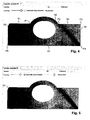
- FIG. 4 shows an example of such an image with the illustrated template 5 against the background 8.
- the image of the template is already superimposed on a segmented outline, which is generated automatically, for example, as described below.
- Individual segments of the outline are denoted by S1, S2, S3, etc., individual transition points to P1, P2, P3, etc.
- Outline recognition An edge area of the template 5 is automatically detected in a first image analysis due to differences (eg hue, brightness, color saturation, etc.) between the background 8 and the template 5. Because of the spatial discretization of the digital image into individual pixels, a set of edge pixels is usually determined which belong to the transition region, that is to say lie in color between the color of the template 5 and the color of the background 8. When segmenting the outline, a sequence of segments is determined which each connect to one another at transition points. The segments are each of an elementary linetype. Elementary line types are in particular straight lines, circular arcs or splines (square or cubic splines, or higher-order splines).
- Each segment lies optimally in a set of edge pixels, for example by minimizing a sum of the square deviation of the edge pixels from the segment.
- the transition points between the segments are determined; so that a combined optimization takes place.
- Corresponding algorithms for segmentation are known in principle and are partly integrated in commercially available graphics programs, but without integrated logic, which is useful for automatic recognition and measurement of templates.
- splines are not automatically detected, but can be added only by hand in a later step. This avoids that each imprecisely cut segment is represented by a spline (instead of a straight line or a circular arc).
- a desired fineness of the segmentation, and associated local accuracy, is preferably fixed as a parameter of the segmentation or selectable by the user.
- the fineness may be specified, for example, by a minimum segment length in pixels or millimeters, or by some other measure.
- a control slider for entering the initially used fineness with "Accuracy" designated. This determines whether a section of the outline is divided into many short segments or a longer one.
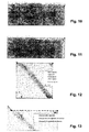
- FIG. 5 shows a subsequent refinement of the segmentation by a user selection of an option "Automatic Improvement” and a free choice of fineness by means of a control slider.
- the segmentation may be repeated for different values of fineness until the result meets expectations. It is thus an intuitive and very easy-to-use adjustment of fineness possible.
- a bevelled corner with segment S7 was also detected.
- FIGS. 6 to 9 show by way of example the modification of a segment type.
- the curved portion of the template has been approximated by the automatic segmentation by a circular arc. The accuracy does not seem to be sufficient for the operator, whereupon he selects the arc and activates a contextual pop-up menu.
- this offers the option "Convert to spline segment", ie the conversion into a segment of splines.
- the section is approximated by a spline curve, in which case, for example, the default is that the spline curve has four control points (also Has "handles"), see FIG. 7 , The outermost two control points, marked by squares, are at the same time the transition points to the adjacent segments, the remaining control points are marked by circles.
- FIG. 7 a contextual menu of the spline curve.
- This has the option "Change amount of curvepoints", ie the change of the number of control points, whereupon in a subsequent input step according to FIG. 8 a number as in this case 12 can be entered. Accordingly, a spline with 12 control points is created and automatically optimally adapted to the contour, see FIG. 9 ,
- FIGS. 10 and 11 show the manual movement of a transition point by selecting such a point by clicking ( FIG. 10 ) and moved to another location ( FIG. 11 ).
- FIGS. 12 and 13 show the force of a right angle: A transition point is selected and a contextual menu of the transition point is displayed. This has the option “Angle to 90 °", ie setting the angle to 90 ° ( FIG. 12 ). After selecting this option, another selection menu for determining the boundary conditions will be displayed ( FIG. 13 ). With this it is specified whether and which of the two straight lines can be adapted, ie rotated (for example, their center or, preferably, to the other end), wherein the other straight line usually changes its length. Usually, the shorter of the lines is rotated.
- FIG. 14 shows the finished segmentation of the template from the previous figures, with the angles and transition and control points displayed.
- the segmentation of the inner contour along the opening or recess in the template is done in a manner analogous to that of the Outer contour.
- a program function "Export” a file with a CAD system-compatible representation of the contours is generated and stored or transmitted to another program or computer system.
- FIG. 15 shows such an exported representation of an outline of the same template 5 (with slightly different segmentation of the round part) as imported and displayed in a CAD program. It also shows the outline of the object corresponding to the oval hole or cutout.
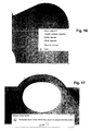
- FIGS. 16 to 19 exemplify further functions for the modification of the segmentation:
- FIG. 16 shows the fitting of tangents by selecting successive segments.
- a contextual menu is displayed, which among other things offers the function "Tangent multiple Segments", ie the creation of tangents to several segments.
- a subsequent selection menu (not shown) allows the selection under different boundary conditions, for example “maintain circle radius”, “change straight line”, “fix one or more segments” etc. "Fixing" means that the selected fixed segments must not be changed, and so the remaining segments have to be adjusted to the fixed ones.
- FIG. 17 shows the result after the multiple execution of a function "Refine Segment”, ie “Refine Segment” until a maximum fineness is reached, which means that due to the discretization of the image in pixels no meaningful segmentation with even shorter segments is possible.
- FIG. 18 shows a subsequent to the state according to the FIG. 17 merging or combining segments into a straight line. This is for illustration only, as the deviation from the actual contour is too great here. Instead, it makes more sense to use a segmental combination of segments of the segment FIG. 17 to a sequence of splines or possibly circular arcs according to FIG. 19 ,
Landscapes
- Physics & Mathematics (AREA)
- Engineering & Computer Science (AREA)
- Geometry (AREA)
- General Physics & Mathematics (AREA)
- Theoretical Computer Science (AREA)
- Computer Graphics (AREA)
- Software Systems (AREA)
- Computer Vision & Pattern Recognition (AREA)
- Image Analysis (AREA)
Applications Claiming Priority (1)
| Application Number | Priority Date | Filing Date | Title |
|---|---|---|---|
| CH8872007 | 2007-06-05 |
Publications (1)
| Publication Number | Publication Date |
|---|---|
| EP2000978A2 true EP2000978A2 (fr) | 2008-12-10 |
Family
ID=39739684
Family Applications (1)
| Application Number | Title | Priority Date | Filing Date |
|---|---|---|---|
| EP08405151A Withdrawn EP2000978A2 (fr) | 2007-06-05 | 2008-06-04 | Procédé de mesure d'un gabarit |
Country Status (1)
| Country | Link |
|---|---|
| EP (1) | EP2000978A2 (fr) |
Cited By (2)
| Publication number | Priority date | Publication date | Assignee | Title |
|---|---|---|---|---|
| ITMI20130137A1 (it) * | 2013-01-31 | 2014-08-01 | Graf Synergy Srl | Metodo ed apparecchiatura di definizione di perimetro di profilo per tubolari |
| CN115760860A (zh) * | 2023-01-05 | 2023-03-07 | 广东技术师范大学 | 一种基于dxf文件导入的多类型工件尺寸视觉测量方法 |
-
2008
- 2008-06-04 EP EP08405151A patent/EP2000978A2/fr not_active Withdrawn
Cited By (3)
| Publication number | Priority date | Publication date | Assignee | Title |
|---|---|---|---|---|
| ITMI20130137A1 (it) * | 2013-01-31 | 2014-08-01 | Graf Synergy Srl | Metodo ed apparecchiatura di definizione di perimetro di profilo per tubolari |
| WO2014118728A1 (fr) * | 2013-01-31 | 2014-08-07 | Graf Synergy S.R.L. | Procédé et appareil permettant de souder des produits tubulaires |
| CN115760860A (zh) * | 2023-01-05 | 2023-03-07 | 广东技术师范大学 | 一种基于dxf文件导入的多类型工件尺寸视觉测量方法 |
Similar Documents
| Publication | Publication Date | Title |
|---|---|---|
| DE3688705T2 (de) | Verfahren und vorrichtung zum automatischen zuschneiden von gemustertem textilmaterial. | |
| DE69312401T2 (de) | Vorrichtung und verfahren zur erzeugung von linien von variabler breite | |
| DE3888825T2 (de) | Graphisches Eingangs-/Ausgangssystem und Verfahren. | |
| DE102007043923A1 (de) | System und Verfahren zum Berechnen von Verbundflächen unter Verwendung von 3D-Abtastdaten | |
| DE102015107025B4 (de) | Verfahren und Prozessparameterwert-Ermittlungseinrichtung zur Ermittlung und Anzeige von Prozessparameterwerten in einem Spritzgussprozess, Verfahren zur Steuerung und Steuereinrichtung für eine Spritzgießanlage sowie Spritzgießanlage | |
| DE102013217354B4 (de) | Kantenmessungs-videowerkzeug und schnittstelle mit automatischen parametersatzalternativen | |
| DE102007021697A1 (de) | System und Verfahren für Gitter- und Körperhybridmodellierung unter Benutzung von 3D-Abtastdaten | |
| DE69422885T2 (de) | Vorrichtung zur Segmentierung von Fingerabdruckbildern für Zehnfingerkarten | |
| DE10346690A1 (de) | Bildverarbeitungsvorrichtung und Bildverarbeitungsverfahren | |
| EP4182101B1 (fr) | Procédé et machine d'enroulement de ressorts pour produire des ressorts hélicoïdaux | |
| DE3615906A1 (de) | Bildinformationserkennungsgeraet | |
| DE102017001010A1 (de) | Bildmessvorrichtung und Programm | |
| DE10122699A1 (de) | Verfahren und Vorrichtung zum Erzeugen von Teileprogrammen zur Verwendung in Bildmessinstrumenten, und Bildmessinstrument und Verfahren zur Darstellung damit gemessener Ergebnisse | |
| DE102015011109A1 (de) | Verfahren zur erzeugung eines dreidimensionalen modells, system 5 zur erzeugung eines dreidimensionalen modells und programm zur erzeugung eines dreidimensionalen modells | |
| EP3274654B1 (fr) | Procédé, dispositif et produit programme d'ordinateur de détermination de propriétés en matière de dimension d'un objet mesuré | |
| DE10238267B4 (de) | Teilprogramm-Erzeugungsvorrichtung und Programm für eine Bildmessvorrichtung | |
| DE69032934T2 (de) | Verfahren und Gerät zur semi-automatischen Bildablaufverfolgung | |
| EP4078309A1 (fr) | Procédé et dispositif de détermination de paramètres de coupe d'une machine de coupe au laser | |
| DE69033105T2 (de) | Verfahren und Gerät zur graphischen Verarbeitung | |
| DE102008004578B4 (de) | Verfahren zum Messen eines mit mindestens einer Schneide versehenen Rotationswerkzeuges sowie Messvorrichtung hierfür | |
| DE3324736A1 (de) | Eingabe-/ausgabesystem fuer die bilddarstellung | |
| DE102013217347B4 (de) | Verfahren und vorrichtung zur parametereinstellung für kantenmessungsvideowerkzeuge | |
| EP2000978A2 (fr) | Procédé de mesure d'un gabarit | |
| DE10112008A1 (de) | Bildverarbeitungsvorrichtung und computerlesbares Speichermedium | |
| DE69630025T2 (de) | Kontrolle eines Infrarotmikroskops |
Legal Events
| Date | Code | Title | Description |
|---|---|---|---|
| PUAI | Public reference made under article 153(3) epc to a published international application that has entered the european phase |
Free format text: ORIGINAL CODE: 0009012 |
|
| AK | Designated contracting states |
Kind code of ref document: A2 Designated state(s): AT BE BG CH CY CZ DE DK EE ES FI FR GB GR HR HU IE IS IT LI LT LU LV MC MT NL NO PL PT RO SE SI SK TR |
|
| AX | Request for extension of the european patent |
Extension state: AL BA MK RS |
|
| STAA | Information on the status of an ep patent application or granted ep patent |
Free format text: STATUS: THE APPLICATION IS DEEMED TO BE WITHDRAWN |
|
| 18D | Application deemed to be withdrawn |
Effective date: 20110104 |