EP2000978A2 - Method for measuring a template - Google Patents
Method for measuring a template Download PDFInfo
- Publication number
- EP2000978A2 EP2000978A2 EP08405151A EP08405151A EP2000978A2 EP 2000978 A2 EP2000978 A2 EP 2000978A2 EP 08405151 A EP08405151 A EP 08405151A EP 08405151 A EP08405151 A EP 08405151A EP 2000978 A2 EP2000978 A2 EP 2000978A2
- Authority
- EP
- European Patent Office
- Prior art keywords
- template
- segments
- segmentation
- outline
- measuring
- Prior art date
- Legal status (The legal status is an assumption and is not a legal conclusion. Google has not performed a legal analysis and makes no representation as to the accuracy of the status listed.)
- Withdrawn
Links
Images


Classifications
-
- G—PHYSICS
- G06—COMPUTING OR CALCULATING; COUNTING
- G06T—IMAGE DATA PROCESSING OR GENERATION, IN GENERAL
- G06T17/00—Three-dimensional [3D] modelling for computer graphics
- G06T17/10—Constructive solid geometry [CSG] using solid primitives, e.g. cylinders, cubes
-
- G—PHYSICS
- G06—COMPUTING OR CALCULATING; COUNTING
- G06T—IMAGE DATA PROCESSING OR GENERATION, IN GENERAL
- G06T7/00—Image analysis
- G06T7/10—Segmentation; Edge detection
- G06T7/12—Edge-based segmentation
Definitions
- the invention relates to the field of metrological detection of templates, so that a numerically controlled processing machine for producing a plate according to the template shape is controllable.
- the invention relates in particular to a method, a measuring device and a computer program for measuring a template and for generating a computer-readable representation of the outline of the template according to the preamble of the corresponding independent patent claims.
- This object is achieved by a method for measuring a template and for generating a computer-readable representation of the outlines of the template with the features of claim 1.
- the computer-readable representation of the outline of the template is generated with a program that covers the entire process, from the image acquisition by a camera to the output of the computer-readable representation for a processing machine.
- the program is executed in an image capture device with a measurement surface and a camera, which can be controlled by the program, and the program automatically corrects aberrations of the optics of the camera. It is thus automatically generated a segmentation of the outlines of a template, which is provided in a computer-readable representation for a processing machine. In this case, only a modification of the segmentation by the user is necessary, in contrast to a free tracing the outlines of the template.
- the thus generated representation of the outline of the template thus also includes the correct sizes of the segments, which in one machine-readable format can be exported, preferably in the format DXF (AutoCad Drawing eXchange Format).
- the exported file can be stored, further processed in a CAD program or transferred via a communication interface to a processing machine.
- Other preferred types may be “circle” or “ellipse” or other elementary geometric shapes.
- transition points are preferably only automatically inserted and thereby positioned, and preferably can only be moved or deleted by the user.
- Free drawing functions or freehand functions are preferably not available to the user. Thus, no calculations and corresponding mathematical knowledge of the User is required, and it simplifies and speeds up user interaction.
- a thickness of the template is automatically taken into account in the dimensioning (ie in the assignment of lengths and angles) of the segments by the thickness is detected - by an automatic distance measurement or by a user input - and the actual position of pictured, ie is corrected by the camera, outline points due to their thickness is corrected over the measuring surface.
- contour recognition and refinement apply to outer contours as well as to inner contours, ie also to cutouts or holes in the stencils.
- inner contours ie also to cutouts or holes in the stencils.
- further functions are preferably realized, for example, a command "detected inner contour", which triggers the search for edge points respectively objects within the template and their segmentation, or a function for moving or rotating an inner contour as a whole.
- entire inner contours, or else sections, ie segment sequences of inner or outer contours are selected from a library of standard contours, retrieved and used instead of an automatically segmented contour.
- known shapes of various types of sinks that can be embedded in a panel can be stored and retrieved as interior contours.
- the measuring device for measuring a template and for generating a computer-readable representation of the outline of the template has a measuring surface, a camera and a data processing unit with input / output devices and an interface for reading in digitized images of the camera, as well as storage means with stored therein computer program code means Describe computer program, and data processing means for executing the computer program, the execution of the computer program for carrying out the method according to the invention leads.
- a computer program product comprises a data carrier, or a computer-readable medium, on which the computer program code means are stored.
- FIG. 1 schematically shows the structure of a measuring device:
- a data processing unit 1 with input / output devices 2, in particular a screen 2a, a keyboard 2b and a mouse 2c or other pointing device is connected to a digital camera 3.
- the camera 3 can be controlled by the data processing unit 1 via a communication connection, in particular image acquisition by the data processing unit 1 can be triggered, and image information can be transmitted from the camera 3 to the data processing unit 1.
- the camera 3 is directed to a measuring surface 4.
- a template 5 can be arranged so that the camera 3 can take an image of the template 5 with the measuring surface 4 as a background.
- the measuring surface 4 is preferably monochrome, in a color which is not commonly used in stencils 5, for example green or blue. This simplifies the recognition of the outline of the template.
- the camera 3 is once aligned and calibrated during setup on the measuring surface 4, and then stopped moving.
- FIG. 2 shows an array of measuring surfaces 6 for aligning the camera 3.
- the measuring surfaces 6 are all the same size and are arranged regularly and at the same distance from the center of the measuring surface 6 around this.
- the data processing unit 1 provides a function which individually determines the area of the measurement areas 6 perceived by the camera 3 for each measurement area 6, for example as a number of pixels.
- the camera is mounted on the surface normal on the center of the measuring surface 6 and oriented in accordance with these perceived surfaces until the perceived surface of all measuring surfaces 6 is the same size.
- measuring marks are placed on the measuring surface 4 at defined intervals. From the distances in pixels perceived by the camera 3, corresponding conversion factors can be determined.
- FIG. 3 schematically shows the conditions in the correction of measurements according to the stencil thickness, wherein the thickness of the template 5 is greatly exaggerated: A point P_real on the edge of the template 5 with thickness h by the camera 3 as point P_obs at the level of the measuring surface 4th perceived.
- the distance d from the camera 3 to the measuring surface 4 is known from the device and calibration of the camera 3, and the horizontal position d_obs of the detected point can be determined.
- the actual horizontal position d_real results from this using elementary trigonometry. For specifying real measured values, ie in millimeters instead of pixels, the values corrected in this way are used in each case.
- This correction of the calibration is carried out, for example, before the segmentation for the entire image, so that all further masses, ie lengths and angles, can be read out of the correctly scaled image.
- the correction can also be made later so that lengths and positions are processed as values in pixel space, and rescaled only for display to the user as millimeters, for example.
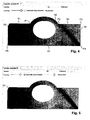
- FIG. 4 shows an example of such an image with the illustrated template 5 against the background 8.
- the image of the template is already superimposed on a segmented outline, which is generated automatically, for example, as described below.
- Individual segments of the outline are denoted by S1, S2, S3, etc., individual transition points to P1, P2, P3, etc.
- Outline recognition An edge area of the template 5 is automatically detected in a first image analysis due to differences (eg hue, brightness, color saturation, etc.) between the background 8 and the template 5. Because of the spatial discretization of the digital image into individual pixels, a set of edge pixels is usually determined which belong to the transition region, that is to say lie in color between the color of the template 5 and the color of the background 8. When segmenting the outline, a sequence of segments is determined which each connect to one another at transition points. The segments are each of an elementary linetype. Elementary line types are in particular straight lines, circular arcs or splines (square or cubic splines, or higher-order splines).
- Each segment lies optimally in a set of edge pixels, for example by minimizing a sum of the square deviation of the edge pixels from the segment.
- the transition points between the segments are determined; so that a combined optimization takes place.
- Corresponding algorithms for segmentation are known in principle and are partly integrated in commercially available graphics programs, but without integrated logic, which is useful for automatic recognition and measurement of templates.
- splines are not automatically detected, but can be added only by hand in a later step. This avoids that each imprecisely cut segment is represented by a spline (instead of a straight line or a circular arc).
- a desired fineness of the segmentation, and associated local accuracy, is preferably fixed as a parameter of the segmentation or selectable by the user.
- the fineness may be specified, for example, by a minimum segment length in pixels or millimeters, or by some other measure.
- a control slider for entering the initially used fineness with "Accuracy" designated. This determines whether a section of the outline is divided into many short segments or a longer one.
- FIG. 5 shows a subsequent refinement of the segmentation by a user selection of an option "Automatic Improvement” and a free choice of fineness by means of a control slider.
- the segmentation may be repeated for different values of fineness until the result meets expectations. It is thus an intuitive and very easy-to-use adjustment of fineness possible.
- a bevelled corner with segment S7 was also detected.
- FIGS. 6 to 9 show by way of example the modification of a segment type.
- the curved portion of the template has been approximated by the automatic segmentation by a circular arc. The accuracy does not seem to be sufficient for the operator, whereupon he selects the arc and activates a contextual pop-up menu.
- this offers the option "Convert to spline segment", ie the conversion into a segment of splines.
- the section is approximated by a spline curve, in which case, for example, the default is that the spline curve has four control points (also Has "handles"), see FIG. 7 , The outermost two control points, marked by squares, are at the same time the transition points to the adjacent segments, the remaining control points are marked by circles.
- FIG. 7 a contextual menu of the spline curve.
- This has the option "Change amount of curvepoints", ie the change of the number of control points, whereupon in a subsequent input step according to FIG. 8 a number as in this case 12 can be entered. Accordingly, a spline with 12 control points is created and automatically optimally adapted to the contour, see FIG. 9 ,
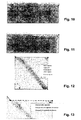
- FIGS. 10 and 11 show the manual movement of a transition point by selecting such a point by clicking ( FIG. 10 ) and moved to another location ( FIG. 11 ).
- FIGS. 12 and 13 show the force of a right angle: A transition point is selected and a contextual menu of the transition point is displayed. This has the option “Angle to 90 °", ie setting the angle to 90 ° ( FIG. 12 ). After selecting this option, another selection menu for determining the boundary conditions will be displayed ( FIG. 13 ). With this it is specified whether and which of the two straight lines can be adapted, ie rotated (for example, their center or, preferably, to the other end), wherein the other straight line usually changes its length. Usually, the shorter of the lines is rotated.
- FIG. 14 shows the finished segmentation of the template from the previous figures, with the angles and transition and control points displayed.
- the segmentation of the inner contour along the opening or recess in the template is done in a manner analogous to that of the Outer contour.
- a program function "Export” a file with a CAD system-compatible representation of the contours is generated and stored or transmitted to another program or computer system.
- FIG. 15 shows such an exported representation of an outline of the same template 5 (with slightly different segmentation of the round part) as imported and displayed in a CAD program. It also shows the outline of the object corresponding to the oval hole or cutout.
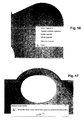
- FIGS. 16 to 19 exemplify further functions for the modification of the segmentation:
- FIG. 16 shows the fitting of tangents by selecting successive segments.
- a contextual menu is displayed, which among other things offers the function "Tangent multiple Segments", ie the creation of tangents to several segments.
- a subsequent selection menu (not shown) allows the selection under different boundary conditions, for example “maintain circle radius”, “change straight line”, “fix one or more segments” etc. "Fixing" means that the selected fixed segments must not be changed, and so the remaining segments have to be adjusted to the fixed ones.
- FIG. 17 shows the result after the multiple execution of a function "Refine Segment”, ie “Refine Segment” until a maximum fineness is reached, which means that due to the discretization of the image in pixels no meaningful segmentation with even shorter segments is possible.
- FIG. 18 shows a subsequent to the state according to the FIG. 17 merging or combining segments into a straight line. This is for illustration only, as the deviation from the actual contour is too great here. Instead, it makes more sense to use a segmental combination of segments of the segment FIG. 17 to a sequence of splines or possibly circular arcs according to FIG. 19 ,
Landscapes
- Physics & Mathematics (AREA)
- Engineering & Computer Science (AREA)
- Geometry (AREA)
- General Physics & Mathematics (AREA)
- Theoretical Computer Science (AREA)
- Computer Graphics (AREA)
- Software Systems (AREA)
- Computer Vision & Pattern Recognition (AREA)
- Image Analysis (AREA)
Abstract
Description
Die Erfindung bezieht sich auf das Gebiet der messtechnischen Erfassung von Schablonen, so dass eine numerisch gesteuerte Bearbeitungsmaschine zur Herstellung einer Platte entsprechend der Schablonenform ansteuerbar ist. Die Erfindung bezieht sich insbesondere auf ein Verfahren, eine Messeinrichtung und ein Computerprogramm zum Vermessen einer Schablone und zum Erzeugen einer computerlesbaren Darstellung der Umrisse der Schablone gemäss dem Oberbegriff der entsprechenden unabhängigen Patentansprüche.The invention relates to the field of metrological detection of templates, so that a numerically controlled processing machine for producing a plate according to the template shape is controllable. The invention relates in particular to a method, a measuring device and a computer program for measuring a template and for generating a computer-readable representation of the outline of the template according to the preamble of the corresponding independent patent claims.
Bei der Herstellung von Steinplatten für beispielsweise den Küchenbau ist es üblich, Steinplatten individuell entsprechend den Massen einer Einbauküche anzufertigen. Dafür werden die genauen Masse der gewünschten Platte durch Herstellen einer Schablone erfasst. In einem CAD (Computer Aided Design)-Programm werden die Umrisse der Schablone manuell nachgezeichnet. Eine computerlesbare Beschreibung des so erfassten Umrisses wird durch das CAD-Programm in einem Dateiformat, beispielsweise im Standardformat DXF (AutoCad Drawing eXchange Format), in einer Datei gespeichert. Diese Datei wird durch ein Steuerprogramm einer numerisch gesteuerten Bearbeitungsmaschine eingelesen und gegebenenfalls zusätzlich um Werkzeugparameter ergänzt. Darauf basierend sägt oder fräst die Bearbeitungsmaschine eine Steinplatte in der gewünschten Form.In the production of flagstones for example, the kitchen, it is customary to make stone slabs individually according to the masses of a fitted kitchen. For this, the exact mass of the desired plate is detected by making a template. In a CAD (Computer Aided Design) program, the outlines of the template are traced manually. A computer-readable description of the outline thus acquired is stored in a file by the CAD program in a file format, such as the standard DXF (AutoCad Drawing eXchange Format) format. This file is read in by a control program of a numerically controlled processing machine and optionally supplemented by additional tool parameters. Based on this, the processing machine saws or mills a stone slab in the desired shape.
Dieses Vorgehen bedingt den Einsatz eines kostspieligen und kompliziert zu bedienenden CAD-Programmes. Durch Vermessen der Schablone mit einem Massband und durch manuelles Nachzeichnen im CAD-Programm entstehen Fehler, und der ganze Erfassungsprozess dauert relativ lange.This procedure requires the use of a costly and complicated to use CAD program. Measuring the template with a measuring tape and manual tracing in the CAD program causes errors, and the entire acquisition process takes a relatively long time.
Es ist deshalb Aufgabe der Erfindung, ein Verfahren, eine Messeinrichtung und ein Computerprogramm zum Vermessen einer Schablone und zum Erzeugen einer computerlesbaren Darstellung der Umrisse der Schablone der eingangs genannten Art zu schaffen, welche die oben genannten Nachteile behebt.It is therefore an object of the invention to provide a method, a measuring device and a computer program for measuring a template and for generating a computer-readable representation of the outline of the template of the type mentioned, which overcomes the disadvantages mentioned above.
Diese Aufgabe löst ein Verfahren zum Vermessen einer Schablone und zum Erzeugen einer computerlesbaren Darstellung der Umrisse der Schablone mit den Merkmalen des Patentanspruches 1.This object is achieved by a method for measuring a template and for generating a computer-readable representation of the outlines of the template with the features of
Es wird also die computerlesbare Darstellung der Umrisse der Schablone mit einem Programm erzeugt, welches den gesamten Prozess, von der Bildaufnahme durch eine Kamera bis zur Ausgabe der computerlesbaren Darstellung für eine Bearbeitungsmaschine abdeckt. Das Programm wird in einer Bilderfassungsvorrichtung mit einer Messfläche und einer Kamera, welche durch das Programm ansteuerbar ist, und wobei das Programm Abbildungsfehler der Optik der Kamera automatisch korrigiert, ausgeführt. Es wird damit automatisch eine Segmentierung der Umrisse einer Schablone erzeugt, welche in einer computerlesbaren Darstellung für eine Bearbeitungsmaschine bereitgestellt wird. Dabei ist lediglich eine Modifikation der Segmentierung durch den Benutzer notwendig, im Gegensatz zu einem freien Nachzeichnen der Umrisse der Schablone. Die so erzeugte Darstellung der Umrisse der Schablone beinhaltet also auch die richtigen Grössen der Segmente, die in ein maschinenlesbares Format exportiert werden können, vorzugsweise in das Format DXF (AutoCad Drawing eXchange Format). Die exportierte Datei kann abgelegt, in einem CAD-Programm weiterbearbeitet oder über eine Kommunikationsschnittstelle an eine Bearbeitungsmaschine übertragen werden.Thus, the computer-readable representation of the outline of the template is generated with a program that covers the entire process, from the image acquisition by a camera to the output of the computer-readable representation for a processing machine. The program is executed in an image capture device with a measurement surface and a camera, which can be controlled by the program, and the program automatically corrects aberrations of the optics of the camera. It is thus automatically generated a segmentation of the outlines of a template, which is provided in a computer-readable representation for a processing machine. In this case, only a modification of the segmentation by the user is necessary, in contrast to a free tracing the outlines of the template. The thus generated representation of the outline of the template thus also includes the correct sizes of the segments, which in one machine-readable format can be exported, preferably in the format DXF (AutoCad Drawing eXchange Format). The exported file can be stored, further processed in a CAD program or transferred via a communication interface to a processing machine.
Durch den Automatismus und die Einschränkung der Möglichkeiten auf die einzig logischen Schritte ist eine effiziente und äusserst einfache Bedienung möglich, durch die Zeit eingespart und Fehler vermieden werden können. Es wird somit auch möglich, auf die Verwendung eines CAD-Programmes zu verzichten.By the automatism and the restriction of the possibilities on the only logical steps an efficient and extremely simple operation is possible, by which time can be saved and mistakes can be avoided. It is therefore also possible to dispense with the use of a CAD program.
In einer bevorzugten Ausführungsform des Erfindungsgegenstandes sind die Segmente von einem der Typen "Gerade", "Kreisbogen" oder "Spline", und schliessen Segmente jeweils an Übergangspunkten aneinander an. Weitere bevorzugte Typen können "Kreis" oder "Ellipse" oder andere elementare geometrische Formen sein.In a preferred embodiment of the subject invention, the segments of one of the types "straight", "arc" or "spline", and connect segments each at transition points to each other. Other preferred types may be "circle" or "ellipse" or other elementary geometric shapes.
Die Modifikation der Segmentierung des Umrisses umfasst mindestens eine der folgenden Gruppe von Modifikationsarten:
- Umwandeln des Typs eines Segmentes;
- Verschieben eines Übergangspunktes zwischen zwei Segmenten;
- Zusammenfassen von mehreren Segmenten zu einem Segment; und
- Aufteilen eines Segments in zwei oder mehr Segmente.
- Converting the type of a segment;
- Shifting a transition point between two segments;
- Combining multiple segments into a segment; and
- Splitting a segment into two or more segments.
Dies bedeutet also, dass Übergangspunkte vorzugsweise nur automatisch eingefügt und dabei positioniert werden, und durch den Benutzer vorzugsweise nur verschoben oder gelöscht werden können. Freie Zeichenfunktionen oder Freihandfunktionen, beispielsweise zum Nachzeichnen eines Umrisses, insbesondere einer von Hand vermessenen Schablone, stehen dem Benutzer vorzugsweise nicht zur Verfügung. Damit sind keine Berechnungen und entsprechenden mathematischen Kenntnisse des Benutzers erforderlich, und es wird die Benutzerinteraktion vereinfacht und beschleunigt.This means that transition points are preferably only automatically inserted and thereby positioned, and preferably can only be moved or deleted by the user. Free drawing functions or freehand functions, for example for tracing an outline, in particular a manually measured template, are preferably not available to the user. Thus, no calculations and corresponding mathematical knowledge of the User is required, and it simplifies and speeds up user interaction.
In einer bevorzugten Ausführungsform der Erfindung weist die Modifikation der Segmentierung des Umrisses die folgenden Schritte auf:
- Erfassen einer Benutzereingabe zum Auswählen eines oder mehrerer Segmente.
- Erfassen einer Benutzereingabe zur Spezifikation einer geometrischen Eigenschaft des oder der ausgewählten Segmente. Eine solche Eigenschaft ist beispielsweise die Länge eines geraden Segmentes, ein Winkel zwischen zwei geraden Segmenten, die Parallelität zweier geraden Segmente, ein knickfreier Übergang zwischen zwei Segmenten, etc.
- Automatisches Anpassen des oder der ausgewählten Segmente an die eingegebene Eigenschaft, und gegebenenfalls auch Anpassen von angrenzenden Segmenten. Vorzugsweise sind - je nach Art der Modifikation - Randbedingungen wählbar, unter denen die Anpassung geschehen muss.
- Detecting a user input to select one or more segments.
- Detecting a user input for specifying a geometric property of the selected one or segments. Such a property is, for example, the length of a straight segment, an angle between two straight segments, the parallelism of two straight segments, a kink-free transition between two segments, etc.
- Automatically adjust the selected segment (s) to the entered property, and optionally, trim adjacent segments. Preferably, depending on the type of modification, boundary conditions can be selected under which the adaptation must be made.
Konkrete, beispielhafte Sequenzen zur Modifikation sind die Folgenden (aus der Sicht des Benutzers gesehen; eine Auswahl oder eine Eingabe des Benutzers ist also als Erfassen entsprechender Angaben durch das computerbasierte Verfahren zu verstehen):
- a) Auswählen eines Winkels (bei einem Übergangspunkt) zwischen zwei Geraden. b) Vorgabe eines Wertes für den Winkel. c) Auswahl einer Randbedingung zur Angabe, welche der Geraden verschoben werden soll. Die Auswahl kann durch den Benutzer geschehen, es kann aber beispielsweise auch automatisch vorgeschlagen oder vorgegeben werden, dass die kürzere Gerade verschoben werden soll, oder die zuletzt modifizierte Gerade nicht verschoben werden darf.
- a) Auswählen einer Geraden. b) Vorgabe eines Längenwertes für die Gerade, beispielsweise entsprechend der realen, an der Schablone gemessenen Länge der Geraden in Millimetern. b) Auswahl einer Randbedingung zur Angabe, welcher der Endpunkte der Geraden verschoben werden soll, und ob die Gerade ihre Neigung ändern darf oder nicht.
- a) Auswählen eines Kreisbogens und eines oder zweier an diesen Kreisbogen anschliessenden geraden Segmente. b) Auswahl einer Funktion, welche erzwingt, dass die Geraden tangential zum Kreisbogen sind. c) Dabei Angabe von Randbedingungen, ob beispielsweise der Durchmesser des Kreisbogens und/oder sein Mittelpunkt und/oder die Neigung der Geraden geändert werden darf.
- a) Auswählen zweier Geraden. b) Auswahl einer Funktion, welche erzwingt, dass die beiden Geraden parallel sind. c) Dabei Angabe von Randbedingungen, beispielsweise welche der Geraden ihre Neigung beibehält.
- a) Auswählen mehrerer Kreisbögen. b) Auswahl einer Funktion, welche erzwingt, dass alle Kreisbögen denselben Radius aufweisen. c) Dabei Angabe von Randbedingungen, beispielsweise welcher Radius massgebend sein soll, oder ob ein Durchschnittsradius gewählt werden soll, oder der Radius via Benutzereingabe festgelegt wird.
- a) Auswählen eines oder mehrerer Segmente. b) Auswahl einer Funktion, welche die Segmente um ein bestimmtes Mass nach aussen verschiebt (Offset). c) Dabei Angabe, wie weit die Verschiebung sein soll, und wie angrenzende Segmente angepasst werden sollen, beispielsweise durch Parallelverschiebung oder durch Änderung von Kreisradien. Dadurch können vorstehende Ränder, beispielsweise bei einer Platte in einer Küchenkombination, auf einfache Weise erzeugt werden.
- a) Erfassen von Benutzereingaben zur Markierung von zwei Punkten im Bild der Schablone; b) Erfassen einer Benutzereingabe zur Spezifikation eines gemessenen Abstandes zwischen den beiden Punkten der Schablone; c) Skalieren der Segmentierung des Umrisses nach Massgabe dieses Abstandes. Auch in dieser Wiese kann a priori-Wissen eingebracht werden, hier aber zur Feinkorrektur der Skalierung des ganzen Umrisses.
- a) Selecting an angle (at a transition point) between two straight lines. b) specification of a value for the angle. c) Selection of a Boundary condition for specifying which of the straight lines should be moved. The selection can be done by the user, but it can also be automatically proposed or specified, for example, that the shorter straight line should be moved, or the last modified straight line may not be moved.
- a) Select a straight line. b) specification of a length value for the straight line, for example, corresponding to the real, measured on the template length of the line in millimeters. b) Selection of a boundary condition for specifying which of the end points of the line should be moved and whether or not the line may change its inclination.
- a) selecting a circular arc and one or two adjacent to this circular arc straight segments. b) Selection of a function which forces the straight lines to be tangent to the circular arc. c) Specification of boundary conditions, for example, whether the diameter of the arc and / or its center and / or the inclination of the line may be changed.
- a) Select two straight lines. b) Selection of a function which forces the two straight lines to be parallel. c) Specification of boundary conditions, for example, which of the straight line retains its slope.
- a) Selecting multiple circular arcs. b) Selection of a function that forces all circular arcs to have the same radius. c) Specification of boundary conditions, for example, which radius is to be decisive, or whether an average radius should be selected, or the radius is set via user input.
- a) Select one or more segments. b) Selection of a function which shifts the segments outwards by a certain amount (offset). c) Indication of how far the shift should be and how adjacent segments are to be adjusted, for example by parallel displacement or by changing circular radii. As a result, projecting edges, for example in a plate in a kitchen combination, can be produced in a simple manner.
- a) detecting user input for marking two points in the image of the template; b) detecting a user input for specifying a measured distance between the two points of the template; c) Scaling the segmentation of the outline according to this distance. Also in this field a priori knowledge can be introduced, but here to fine-tune the scaling of the whole outline.
In einer weiteren bevorzugten Ausführungsform des Erfindungsgegenstandes wird eine Dicke der Schablone automatisch bei der Vermassung (also bei der Zuordnung von Längen und Winkeln) der Segmente berücksichtigt, indem die Dicke erfasst wird - durch eine automatische Distanzmessung oder durch eine Benutzereingabe - und die tatsächliche Lage von abgebildeten, d.h. durch die Kamera wahrgenommenen, Umrisspunkten aufgrund ihrer Dicke über der Messfläche korrigiert wird.In a further preferred embodiment of the subject invention, a thickness of the template is automatically taken into account in the dimensioning (ie in the assignment of lengths and angles) of the segments by the thickness is detected - by an automatic distance measurement or by a user input - and the actual position of pictured, ie is corrected by the camera, outline points due to their thickness is corrected over the measuring surface.
Die beschriebenen Schritte zur Umrisserkennung und -verfeinerung gelten für Aussenkonturen wie auch für Innenkonturen, also auch für Ausschnitte respektive Löcher in den Schablonen. Zur Bearbeitung von erfassten Innenkonturen sind vorzugsweise weitere Funktionen realisiert, beispielsweise ein Befehl "erfasse Innenkontur", welcher die Suche nach Randpunkten respektive Objekten innerhalb der Schablone und deren Segmentierung auslöst, oder eine Funktion zum Verschieben oder Verdrehen einer Innenkontur als ganzer.The steps described for contour recognition and refinement apply to outer contours as well as to inner contours, ie also to cutouts or holes in the stencils. For the processing of detected inner contours further functions are preferably realized, for example, a command "detected inner contour", which triggers the search for edge points respectively objects within the template and their segmentation, or a function for moving or rotating an inner contour as a whole.
In weiteren bevorzugten Ausführungsformen der Erfindung werden ganze Innenkonturen, oder auch Abschnitte, d.h. Segmentfolgen von Innen- oder Aussenkonturen, aus einer Bibliothek von Standardkonturen ausgewählt, abgerufen und anstelle einer automatisch segmentierten Kontur eingesetzt. Damit ist es möglich, bekannte normierte Formen einzusetzen, ohne sie genau ausmessen zu müssen. Beispielsweise können bekannte Formen verschiedener Typen von Waschbecken, die in eine Platte eingelassen werden können, als Innenkonturen gespeichert und abgerufen werden.In further preferred embodiments of the invention, entire inner contours, or else sections, ie segment sequences of inner or outer contours, are selected from a library of standard contours, retrieved and used instead of an automatically segmented contour. This makes it possible to use known normalized shapes without having to measure them accurately. For example, known shapes of various types of sinks that can be embedded in a panel can be stored and retrieved as interior contours.
Die Messeinrichtung zum Vermessen einer Schablone und zum Erzeugen einer computerlesbaren Darstellung der Umrisse der Schablone weist eine Messfläche, eine Kamera sowie eine Datenverarbeitungseinheit mit Ein/Ausgabegeräten und einer Schnittstelle zum Einlesen von digitalisierten Bildern der Kamera auf, sowie Speichermittel mit darin gespeicherten Computerprogrammcodemitteln, welche ein Computerprogramm beschreiben, und Datenverarbeitungsmittel zur Ausführung des Computerprogramms, wobei die Ausführung des Computerprogramms zur Durchführung des Verfahrens gemäss der Erfindung führt.The measuring device for measuring a template and for generating a computer-readable representation of the outline of the template has a measuring surface, a camera and a data processing unit with input / output devices and an interface for reading in digitized images of the camera, as well as storage means with stored therein computer program code means Describe computer program, and data processing means for executing the computer program, the execution of the computer program for carrying out the method according to the invention leads.
Das Computerprogramm zum Vermessen einer Schablone und zum Erzeugen einer computerlesbaren Darstellung der Umrisse der Schablone ist in einen internen Speicher einer digitalen Datenverarbeitungseinheit ladbar und weist Computerprogrammcodemittel auf, welche, wenn sie in einer digitalen Datenverarbeitungseinheit der Messeinrichtung ausgeführt werden, diese zur Ausführung des erfindungsgemässen Verfahrens bringen. In einer bevorzugten Ausführungsform der Erfindung weist ein Computerprogrammprodukt einen Datenträger, respektive ein computerlesbares Medium auf, auf welchem die Computerprogrammcodemittel gespeichert sind.The computer program for measuring a template and for generating a computer-readable representation of the outline of the template is loadable into an internal memory of a digital data processing unit and has computer program code means which, when executed in a digital data processing unit of the measuring device, bring them to the execution of the inventive method , In a preferred embodiment of the invention, a computer program product comprises a data carrier, or a computer-readable medium, on which the computer program code means are stored.
Weitere bevorzugte Ausführungsformen gehen aus den abhängigen Patentansprüchen hervor. Dabei sind Merkmale der Verfahrensansprüche sinngemäss mit den Vorrichtungsansprüchen kombinierbar und umgekehrt.Further preferred embodiments emerge from the dependent claims. Characteristics of the method claims are analogously combined with the device claims and vice versa.
Im Folgenden wird der Erfindungsgegenstand anhand von bevorzugten Ausführungsbeispielen, welche in den beiliegenden Zeichnungen dargestellt sind, näher erläutert. Es zeigen jeweils schematisch:
-
Figur 1 -
Figur 2 -
Figur 3 -
Figur 4 und 5 -
Figur 6 bis 9 -
Figur 10 und 11 eine Verschiebung eines Übergangspunktes; -
Figur 12 -
Figur 14 eine fertig angepasste Umrisslinie; -
Figur 15 eine exportierte Umrisslinie in einem CAD-Programm; und -
Figur 16 bis 19 weitere Modifikationsmöglichkeiten von Segmenten.
-
FIG. 1 the construction of a measuring device; -
FIG. 2 an array of measurement surfaces for aligning the camera; -
FIG. 3 a correction of measurements according to the stencil thickness. -
FIGS. 4 and 5 Images of a template with automatically detected outline; -
FIGS. 6 to 9 a modification of a round contour section; -
FIGS. 10 and 11 a shift of a transition point; -
FIG. 12 and13 enforcing a right angle; -
FIG. 14 a fully customized outline; -
FIG. 15 an exported outline in a CAD program; and -
FIGS. 16 to 19 further modification options of segments.
Die in den Zeichnungen verwendeten Bezugszeichen und deren Bedeutung sind in der Bezugszeichenliste zusammengefasst aufgelistet. Grundsätzlich sind in den Figuren gleiche Teile mit gleichen Bezugszeichen versehen.The reference numerals used in the drawings and their meaning are listed in the list of reference numerals. Basically, the same parts are provided with the same reference numerals in the figures.
Die
Die Kamera 3 ist auf eine Messfläche 4 gerichtet. Auf der Messfläche 4 kann eine Schablone 5 angeordnet werden, so dass die Kamera 3 ein Bild der Schablone 5 mit der Messfläche 4 als Hintergrund aufnehmen kann. Die Messfläche 4 ist vorzugsweise einfarbig, in einer Farbe, die üblicherweise nicht bei Schablonen 5 verwendet wird, beispielsweise grün oder blau. Dadurch wird die Erkennung des Umrisses der Schablone vereinfacht. Die Kamera 3 wird beim Einrichten einmal auf die Messfläche 4 ausgerichtet und kalibriert, und anschliessend nicht mehr bewegt.The
Zum Kalibrieren der Kamera, d.h. zur Zuordnung von Pixelpositionen zu Positionen auf der Messfläche 4 (in Millimetern) werden vorzugsweise Messmarken in definierten Abständen auf die Messfläche 4 gelegt. Aus den von der Kamera 3 wahrgenommenen Abständen in Pixeln lassen sich entsprechende Umrechnungsfaktoren bestimmen.To calibrate the camera, i. For the assignment of pixel positions to positions on the measuring surface 4 (in millimeters), preferably measuring marks are placed on the measuring
Zum Erzeugen einer computerlesbaren Darstellung der Umrisse der Schablone 5 werden die folgenden Schritte ausgeführt:
- Aufnahme eines Bildes:
Sobald eine Schablone 5 auf der Messfläche 4 plaziert ist, wird durch dieDatenverabeitungseinheit 1, auf einen entsprechenden Benutzerbefehl hin, eine Aufnahme mittels der Kamera 3 ausgelöst. Das erfasste Rohbild wird über die Kameraschnittstelle ausgelesen, also andie Datenverabeitungseinheit 1 übertragen und gespeichert. - Transformieren des Bildes: Das Rohbild weist in der Regel eine Verzerrung auf, welche von der Optik der Kamera 3 abhängt, beispielsweise eine tonnenförmige oder eine kissenförmige Verzeichnung. Die Parameter zur Korrektur solcher Verzerrungen sind teilweise durch den Linsenhersteller zur Verfügung gestellt, oder können experimentell bestimmt werden. Damit wird automatisch eine Korrektur der Verzerrungen durchgeführt und ein entzerrtes Bild erzeugt.
- Taking a picture: As soon as a
template 5 has been placed on the measuringsurface 4, a recording is triggered by thecamera 3 by thedata processing unit 1 in response to a corresponding user command. The captured raw image is read out via the camera interface, that is, transmitted to thedata processing unit 1 and stored. - Transforming the image: The raw image usually has a distortion which depends on the optics of the
camera 3, for example a barrel-shaped or a pincushion-shaped distortion. The parameters for correcting such distortions are partially provided by the lens manufacturer, or may be determined experimentally. This automatically corrects distortions and produces an equalized image.
Vorzugsweise wird dabei auch die Kalibrierung respektive die Skalierung des Bildes an die Dicke der Schablone 5 angepasst:
Umrisserkennung: Ein Randbereich der Schablone 5 wird in einer ersten Bildanalyse aufgrund von Unterschieden (z.B. Farbton, Helligkeit, Farbsättigung etc.) zwischen Hintergrund 8 und Schablone 5 automatisch erkannt. Wegen der räumlichen Diskretisierung des Digitalbildes in einzelne Pixel wird in der Regel eine Menge von Randpixel ermittelt, welche zum Übergangsbereich gehören, also farblich zwischen der Farbe der Schablone 5 und der Farbe des Hintergrunds 8 liegen. Bei der Segmentierung des Umrisses wird eine Folge von Segmenten bestimmt welche jeweils in Übergangspunkten aneinander anschliessen. Die Segmente sind jeweils von einem elementaren Linientyp. Elementare Linientypen sind insbesondere Geraden, Kreisbögen oder Splines (quadratische oder kubische Splines, oder Splines höheren Grades). Jedes Segment liegt möglichst optimal in einer Menge von Randpixel, beispielsweise indem eine Summe der quadratischen Abweichung der Randpixel vom Segment minimiert wird. Vorzugsweise gleichzeitig werden die Übergangspunkte zwischen den Segmenten bestimmt; so dass also eine kombinierte Optimierung stattfindet. Entsprechende Algorithmen zur Segmentierung sind grundsätzlich bekannt und zum Teil in käuflichen Grafikprogrammen integriert, allerdings ohne integrierte Logik, die der automatischen Erkennung und Vermessung von Schablonen dienlich ist. Outline recognition: An edge area of the
In einer bevorzugten Ausführungsform der Erfindung geschieht die Segmentierung in der folgenden Weise:
- 1. Die Pixel des Originalbildes werden in virtuelle Pixel umgewandelt, welche nicht die ursprüngliche Farbinformation enthalten, sondern für die weitere Bildanalyse und Segmentierung dienliche Informationen. Das Bild wird beispielsweise in ein binäres schwarz/weiss-Bild umgewandelt, indem jedes Pixel, das aufgrund der durchgeführten ersten Bildanalyse zur Messfläche gehört, beispielsweise als weiss (Hintergrund) und alle übrigen Pixel als schwarz (Schablone) betrachtet werden. Zuäusserst liegende Pixel der Schablone oder aber Gitterpunkte zwischen den Pixel auf der schwarz/weiss-Grenze werden als Grenzpunkte, Randpunkte oder Umrisspunkte betrachtet.
- 2. Die einzelnen Pixel des erzeugten scharz/weiss Bildes werden analysiert und zu logischen Gruppen (Flächen) oder Objekten zusammengefasst. Diese logischen Gruppen sind Ausgangsbasis für die Erkennung von Segmenten, die zusammen jeweils eine geschlossene Figur ergeben. Ein Objekt ist jeweils eine Schablone oder ein Loch in einer Schablone, welches genau eine geschlossene Umrisslinie aufweist. Ein weiterer Optimierungsschritt analysiert die Objekte aufgrund Ihrer Grösse und schliesst kleine Objekte aus, um Störungen im Bild (z.B. Dreck oder Kratzer auf dem Hintergrund) zu eliminieren.
- 3. Die Segmentierung selbst erfolgt pro Objekt. Zur Segmentierung wird von einem beliebigen Punkt an der schwarz-weiss Grenze ausgegangen, und es wird, der Grenze folgend, ein zweiter Punkt vom Ausgangspunkt weg bewegt und eine Gerade entsprechend den Umrisspunkten zwischen den beiden Punkten bestimmt. Diese Gerade kann eine Ausgleichsgerade (beispielsweise nach der Methode der minimalen Fehlerquadrate) aller Randpunkte zwischen dem ersten und zweiten Punkt sein, oder einfach eine Verbindungsgerade zwischen den beiden Punkten. Die Genauigkeit, bzw. die Varianz, kann mittels eines verschiebbaren Reglers durch den Benutzer eingestellt werden.
- 4. Es wird nach jedem Schritt, den sich der zweite Punkt weiter weg bewegt, ein Mass für die Abweichung der Randpunkte um die Gerade bestimmt. Beispielsweise ist dieses Mass die Varianz der Punkte um die Ausgleichsgerade. In einer anderen Ausführungsform der Erfindung wird ein Toleranzband um die Gerade gelegt, und die Summe der Umrisspunkte, welche sich ausserhalb (bezüglich der Schablone 5) der Geraden befinden, und der Umrisspunkte, die sich innerhalb der Geraden befinden, als Mass für die Abweichung bestimmt.
- 5. Übersteigt das Mass für die Abweichung die über den
Regler gemäss Schritt 3 vorgegebene Genauigkeit, so wird das Ende der Geraden angenommen und wird der zweite Punkt zu einem Übergangspunkt. Anschliessend wird von diesem Übergangspunkt aus gemäss Schritt 3 weitergefahren. - 6. Aufgrund der ermittelten Linien wird in einem zweiten Analyseschritt nach Kreisbögen gesucht. In der bevorzugten Ausführungsform dient die Varianz der Distanz von Randpixeln zum erkannten Liniensegment als Grundlage für die Erkennung von Kreisbögen: Überschreitet die Varianz ein weiteres vorgegebenes Mass, so wird die Menge von Randpunkten durch einen Kreisbogen anstelle einer Geraden angenähert. Die mittels des Reglers eingestellte Genauigkeit ist hierbei von grosser Relevanz, da bei einer Einstellung mit grosser Ungenauigkeit eher Kreissegmente erkannt werden.
- 7. In einem weiteren Analyseschritt werden zwei aufeinanderfolgende Geraden oder Kreisbögen optimiert. Bei zwei Geraden werden unnötige Zwischensegmente gelöscht, die durch die Mittlung der Varianz der Umrisspunkte an Ecken entstehen. Bei zwei aufeinanderfolgenden Kreisbögen werden diese zusammenführt, wenn dies zur Resultatverbesserung beiträgt (zum Beispiel durch Vergleich beider Radien mit dem Radius des zusammengeführten Kreisbogens, Vergleich der Tangenten an den Schnittpunkten, etc.).
- 8. Ein nächster Analyseschritt dient zu weiterer logisch-automatischen Verbesserung der Linien ("Automatic Improvement"). Dieser Analyseschritt beinhaltet nochmaliges Erstellen der Liniensegmente auf einer wesentlich genaueren Basis. Durch die Abtrennung von diesem zusätzlichen Schritt von der allgemeinen Erkennung werden gleichzeitig eine automatisierte Groberkennung von Kreisbögen und eine detaillierte Aufteilung von Geraden in mehrere Segmente ermöglicht. Beispielsweise kann eine Gerade automatisch in einzelne Teilabschnitte aufgeteilt werden, deren Richtung sich nur um einen kleinen Winkel unterscheidet. Auch bei der Verbesserung kann die Genauigkeit durch einen Regler eingestellt werden.
- 1. The pixels of the original image are converted into virtual pixels that do not contain the original color information, but information useful for further image analysis and segmentation. For example, the image is converted to a binary black-and-white image in that each pixel belonging to the measurement surface based on the first image analysis performed, for example, is considered white (background) and all other pixels are considered black (template). Outermost pixels of the template or but grid points between the pixels on the black and white border are considered boundary points, edge points, or outline points.
- 2. The individual pixels of the generated black and white image are analyzed and combined into logical groups (areas) or objects. These logical groups are the starting point for the recognition of segments, which together result in a closed figure. An object is a template or a hole in a template, which has exactly one closed outline. Another optimization step analyzes the objects based on their size and excludes small objects to eliminate image disturbances (eg dirt or scratches on the background).
- 3. The segmentation itself takes place per object. Segmentation is based on any point on the black-and-white border and, following the boundary, a second point is moved away from the starting point and a line is determined according to the outline points between the two points. This straight line may be a straight line (for example, according to the least squares method) of all boundary points between the first and second points, or simply a connecting line between the two points. The accuracy, or the variance, can be adjusted by means of a displaceable regulator by the user.
- 4. A measure of the deviation of the boundary points around the straight line is determined after each step that moves the second point farther away. For example, this measure is the variance of the points around the balancing line. In another embodiment of the invention, a tolerance band is laid around the straight line, and the sum of the outline points which are located outside (with respect to the template 5) of the straight line and the outline points which are located inside the straight line is determined as a measure of the deviation ,
- 5. If the deviation measure exceeds the accuracy specified by the controller in
step 3, the end of the line is assumed and the second point becomes a transition point. Subsequently, the procedure continues from this transition point according tostep 3. - 6. Based on the determined lines, circular arcs are searched in a second analysis step. In the preferred embodiment, the variance of the distance from edge pixels to the recognized line segment serves as the basis for the detection of circular arcs: If the variance exceeds another predetermined measure, the set of edge points is approximated by a circular arc instead of a straight line. The accuracy set by means of the regulator is of great relevance in this case, since in a setting with great inaccuracy, rather circle segments are recognized.
- 7. In a further analysis step, two consecutive straight lines or circular arcs are optimized. Two straight lines delete unnecessary intermediate segments created by averaging the variance of the outline points at corners. For two consecutive circular arcs, these are combined if this contributes to the improvement in the result (for example, by comparing both radii with the radius of the combined circular arc, comparing the tangents at the intersections, etc.).
- 8. A next analysis step is used for further logical-automatic improvement of the lines ("Automatic Improvement"). This analysis step involves recreating the line segments on a much more accurate basis. The separation of this additional step from the general recognition simultaneously enables an automated coarse recognition of arcs and a detailed division of straight lines into several segments. For example, a straight line can be divided automatically into individual sections whose direction differs only by a small angle. Also in the improvement, the accuracy can be adjusted by a regulator.
Vorzugsweise werden Splines nicht automatisch erkannt, sondern lassen sich nur von Hand in einem späteren Schritt zufügen. Damit wird vermieden, dass jedes unpräzis geschnittene Segment durch ein Spline (anstelle einer Gerade oder eines Kreisbogens) repräsentiert wird.Preferably, splines are not automatically detected, but can be added only by hand in a later step. This avoids that each imprecisely cut segment is represented by a spline (instead of a straight line or a circular arc).
Anzeige des segmentierten Umrisses: Das Ergebnis der Segmentierung, also die Folge von Übergangspunkten und Segmenten, wird dem entzerrten Bild überlagert dem Benutzer dargestellt, wie beispielsweise gemäss der
Eine gewünschte Feinheit der Segmentierung, und damit verbunden eine lokale Genauigkeit, ist vorzugsweise als Parameter der Segmentierung fest eingestellt oder durch den Benutzer wählbar. Die Feinheit kann beispielsweise durch eine minimale Segmentlänge in Pixel oder Millimeter spezifiziert werden, oder durch ein anderes Mass. In der
Modifikation der Segmentierung: Nun bietet das System dem Benutzer die Möglichkeit zur Modifikation der Segmentierung. Diese umfasst vorzugsweise nur eine eingeschränkte Auswahl von Funktionen, insbesondere keine freie Zeichenfunktion, bei welcher willkürliche Konturen von Hand gezeichnet werden können. Beispielsweise sind die folgenden Modifikationen möglich, wobei jeweils der Ablauf aus Benutzersicht kurz angegeben ist. Dabei werden in der Regel Segmente oder Übergangspunkte durch Anklicken mit einem Zeigegerät wie einer Maus ausgewählt, und es wird eine Aktion über einem Drop-Down Menu oder ein Fenstermenu oder über eine Funktionstaste ausgelöst.
- Umwandeln des Typs eines Segmentes: Anklicken eines Segmentes, Auswahl einer Funktion "Typ ändern" und Angabe des neuen Typs. Das Segment des neuen Typs wird automatisch so gut wie möglich an den Umriss angeglichen. Anschliessend kann das Segment auch manuell modifiziert werden, beispielsweise durch Anklicken eines Kreisbogens und Ändern seines Radius.
- Verschieben eines Übergangspunktes zwischen zwei Segmenten: Anklicken eines Segmentes, Verschieben des Punktes mit der Maus. Die angrenzenden Segmente werden dem verschobenen Punkt angeglichen.
- Zusammenfassen von mehreren Segmenten zu einem Segment: Auswahl der Segmente, Auswahl einer Funktion "Segmente vereinigen". Zwischen diesen Segmenten liegende Übergangspunkte werden gelöscht. Falls die mehreren Segmente alle Geraden sind, werden sie durch eine einzige Gerade ersetzt, sobald ein Kreisbogen dabei ist, wird das zusammengefasste Segment ebenfalls zu einem Kreisbogen.
- Aufteilen eines Segments in zwei oder mehr Segmente: Auswahl des Segmentes, Auswahl einer Funktion "Segment aufteilen". Dabei findet vorzugsweise eine erneute Segmentierung des ausgewählten Segmentes statt, wie oben geschildert, aber mit grösserer Feinheit. Es werden einer oder mehrere Übergangspunkte eingefügt.
- Converting the type of a segment: Click on a segment, select a function "Change type" and specify the new type. The segment of the new type is automatically aligned as well as possible with the outline. Subsequently, the segment can also be modified manually, for example by clicking on a circular arc and changing its radius.
- Moving a transition point between two segments: Click on a segment, move the point with the mouse. The adjacent segments are aligned to the shifted point.
- Combining several segments into one segment: Selection of the segments, selection of a function "merge segments". Transition points between these segments are deleted. If the multiple segments are all straight lines, they are replaced by a single straight line, as soon as a circular arc is present, the combined segment also becomes a circular arc.
- Splitting a segment into two or more segments: Selecting the segment, selecting a Split Segment function. In this case, a re-segmentation of the selected segment preferably takes place, as described above, but with greater fineness. One or more transition points are inserted.
Um die Annäherung durch die Spline-Kurve zu verfeinern, selektiert der Benutzer diese und aktiviert gemäss
Damit diese Splines oder Kreisbögen ohne Knick in einander übergehen, können sie, ebenfalls gemäss der
- 11
- Datenverabeitungseinheitdata processing unit
- 2a, 2b, 2c2a, 2b, 2c
- Ein/AusgabegeräteI / O devices
- 33
- Kameracamera
- 44
- Messflächemeasuring surface
- 55
- Schablonetemplate
- Snsn
- Segment nSegment n
- Pnpn
- Übergangspunkt nTransition point n
Claims (10)
Applications Claiming Priority (1)
| Application Number | Priority Date | Filing Date | Title |
|---|---|---|---|
| CH8872007 | 2007-06-05 |
Publications (1)
| Publication Number | Publication Date |
|---|---|
| EP2000978A2 true EP2000978A2 (en) | 2008-12-10 |
Family
ID=39739684
Family Applications (1)
| Application Number | Title | Priority Date | Filing Date |
|---|---|---|---|
| EP08405151A Withdrawn EP2000978A2 (en) | 2007-06-05 | 2008-06-04 | Method for measuring a template |
Country Status (1)
| Country | Link |
|---|---|
| EP (1) | EP2000978A2 (en) |
Cited By (2)
| Publication number | Priority date | Publication date | Assignee | Title |
|---|---|---|---|---|
| ITMI20130137A1 (en) * | 2013-01-31 | 2014-08-01 | Graf Synergy Srl | METHOD AND DEFINITION EQUIPMENT OF PROFILE PERIMETER FOR TUBULARS |
| CN115760860A (en) * | 2023-01-05 | 2023-03-07 | 广东技术师范大学 | Multi-type workpiece dimension visual measurement method based on DXF file import |
-
2008
- 2008-06-04 EP EP08405151A patent/EP2000978A2/en not_active Withdrawn
Cited By (3)
| Publication number | Priority date | Publication date | Assignee | Title |
|---|---|---|---|---|
| ITMI20130137A1 (en) * | 2013-01-31 | 2014-08-01 | Graf Synergy Srl | METHOD AND DEFINITION EQUIPMENT OF PROFILE PERIMETER FOR TUBULARS |
| WO2014118728A1 (en) * | 2013-01-31 | 2014-08-07 | Graf Synergy S.R.L. | Method and apparatus for welding tubular products |
| CN115760860A (en) * | 2023-01-05 | 2023-03-07 | 广东技术师范大学 | Multi-type workpiece dimension visual measurement method based on DXF file import |
Similar Documents
| Publication | Publication Date | Title |
|---|---|---|
| DE3688705T2 (en) | METHOD AND DEVICE FOR AUTOMATICALLY CUTTING PATTERNED TEXTILE MATERIAL. | |
| DE69312401T2 (en) | DEVICE AND METHOD FOR PRODUCING VARIABLE WIDTH LINES | |
| DE3888825T2 (en) | Graphical input / output system and method. | |
| DE102007043923A1 (en) | System and method for computing composite surfaces using 3D scan data | |
| DE102015107025B4 (en) | Method and process parameter value determining device for determining and displaying process parameter values in an injection molding process, method for controlling and controlling an injection molding system and injection molding system | |
| DE102013217354B4 (en) | EDGE MEASUREMENT VIDEO TOOL AND INTERFACE WITH AUTOMATIC PARAMETER ALTERNATIVES | |
| DE102007021697A1 (en) | System and method for grid and body hybrid modeling using 3D scan data | |
| DE69422885T2 (en) | Device for segmenting fingerprint images for ten-finger cards | |
| DE10346690A1 (en) | Image processing device and image processing method | |
| EP4182101B1 (en) | Method and spring winding machine for producing coil springs | |
| DE3615906A1 (en) | IMAGE INFORMATION RECOGNITION DEVICE | |
| DE102017001010A1 (en) | Image measuring device and program | |
| DE10122699A1 (en) | Method and device for generating part programs for use in image measuring instruments, and image measuring instrument and method for displaying results measured thereby | |
| DE102015011109A1 (en) | METHOD FOR PRODUCING A THREE-DIMENSIONAL MODEL, SYSTEM 5 FOR GENERATING A THREE-DIMENSIONAL MODEL AND A PROGRAM FOR GENERATING A THREE-DIMENSIONAL MODEL | |
| EP3274654B1 (en) | Method, device and computer program product for determining dimensional properties of a measured object | |
| DE10238267B4 (en) | Sub-program generating device and program for an image measuring device | |
| DE69032934T2 (en) | Method and device for semi-automatic image tracking | |
| EP4078309A1 (en) | Method and device for determining cutting parameters for a laser cutting machine | |
| DE69033105T2 (en) | Method and device for graphic processing | |
| DE102008004578B4 (en) | Method for measuring a rotary tool provided with at least one cutting edge and measuring device therefor | |
| DE3324736A1 (en) | INPUT / OUTPUT SYSTEM FOR IMAGE DISPLAY | |
| DE102013217347B4 (en) | METHOD AND DEVICE FOR PARAMETER ADJUSTMENT FOR EDGE MEASURING VIDEO TOOLS | |
| EP2000978A2 (en) | Method for measuring a template | |
| DE10112008A1 (en) | Image processing device and computer readable storage medium | |
| DE69630025T2 (en) | Control of an infrared microscope |
Legal Events
| Date | Code | Title | Description |
|---|---|---|---|
| PUAI | Public reference made under article 153(3) epc to a published international application that has entered the european phase |
Free format text: ORIGINAL CODE: 0009012 |
|
| AK | Designated contracting states |
Kind code of ref document: A2 Designated state(s): AT BE BG CH CY CZ DE DK EE ES FI FR GB GR HR HU IE IS IT LI LT LU LV MC MT NL NO PL PT RO SE SI SK TR |
|
| AX | Request for extension of the european patent |
Extension state: AL BA MK RS |
|
| STAA | Information on the status of an ep patent application or granted ep patent |
Free format text: STATUS: THE APPLICATION IS DEEMED TO BE WITHDRAWN |
|
| 18D | Application deemed to be withdrawn |
Effective date: 20110104 |