EP2000869A1 - System und Verfahren zum Messen von Maschinenwerkzeugen mit einer Kamera - Google Patents
System und Verfahren zum Messen von Maschinenwerkzeugen mit einer Kamera Download PDFInfo
- Publication number
- EP2000869A1 EP2000869A1 EP07108988A EP07108988A EP2000869A1 EP 2000869 A1 EP2000869 A1 EP 2000869A1 EP 07108988 A EP07108988 A EP 07108988A EP 07108988 A EP07108988 A EP 07108988A EP 2000869 A1 EP2000869 A1 EP 2000869A1
- Authority
- EP
- European Patent Office
- Prior art keywords
- tool
- machining tool
- machining
- measured
- machine
- Prior art date
- Legal status (The legal status is an assumption and is not a legal conclusion. Google has not performed a legal analysis and makes no representation as to the accuracy of the status listed.)
- Ceased
Links
- 238000003754 machining Methods 0.000 title claims abstract description 171
- 238000000034 method Methods 0.000 title claims abstract description 35
- 238000012423 maintenance Methods 0.000 claims description 3
- 230000008439 repair process Effects 0.000 claims description 3
- 230000004044 response Effects 0.000 claims description 2
- 238000005259 measurement Methods 0.000 description 42
- 238000005520 cutting process Methods 0.000 description 35
- 230000005540 biological transmission Effects 0.000 description 9
- 239000000523 sample Substances 0.000 description 7
- 238000010586 diagram Methods 0.000 description 3
- 238000005553 drilling Methods 0.000 description 3
- 238000004519 manufacturing process Methods 0.000 description 3
- 239000000463 material Substances 0.000 description 3
- 238000003801 milling Methods 0.000 description 3
- 230000004323 axial length Effects 0.000 description 2
- 230000008859 change Effects 0.000 description 2
- 230000001276 controlling effect Effects 0.000 description 2
- 238000011156 evaluation Methods 0.000 description 2
- 238000000227 grinding Methods 0.000 description 2
- 230000008569 process Effects 0.000 description 2
- 238000007493 shaping process Methods 0.000 description 2
- 238000009987 spinning Methods 0.000 description 2
- 230000009471 action Effects 0.000 description 1
- 238000004590 computer program Methods 0.000 description 1
- 239000000356 contaminant Substances 0.000 description 1
- 238000013500 data storage Methods 0.000 description 1
- 230000003247 decreasing effect Effects 0.000 description 1
- 238000013461 design Methods 0.000 description 1
- 230000007613 environmental effect Effects 0.000 description 1
- 230000006870 function Effects 0.000 description 1
- 238000010438 heat treatment Methods 0.000 description 1
- 238000005286 illumination Methods 0.000 description 1
- 230000000977 initiatory effect Effects 0.000 description 1
- 230000007246 mechanism Effects 0.000 description 1
- 238000012986 modification Methods 0.000 description 1
- 230000004048 modification Effects 0.000 description 1
- 238000012544 monitoring process Methods 0.000 description 1
- 238000011022 operating instruction Methods 0.000 description 1
- 230000009467 reduction Effects 0.000 description 1
- 230000001105 regulatory effect Effects 0.000 description 1
- 230000001131 transforming effect Effects 0.000 description 1
Images


Classifications
-
- B—PERFORMING OPERATIONS; TRANSPORTING
- B23—MACHINE TOOLS; METAL-WORKING NOT OTHERWISE PROVIDED FOR
- B23Q—DETAILS, COMPONENTS, OR ACCESSORIES FOR MACHINE TOOLS, e.g. ARRANGEMENTS FOR COPYING OR CONTROLLING; MACHINE TOOLS IN GENERAL CHARACTERISED BY THE CONSTRUCTION OF PARTICULAR DETAILS OR COMPONENTS; COMBINATIONS OR ASSOCIATIONS OF METAL-WORKING MACHINES, NOT DIRECTED TO A PARTICULAR RESULT
- B23Q17/00—Arrangements for observing, indicating or measuring on machine tools
- B23Q17/09—Arrangements for observing, indicating or measuring on machine tools for indicating or measuring cutting pressure or for determining cutting-tool condition, e.g. cutting ability, load on tool
-
- B—PERFORMING OPERATIONS; TRANSPORTING
- B23—MACHINE TOOLS; METAL-WORKING NOT OTHERWISE PROVIDED FOR
- B23Q—DETAILS, COMPONENTS, OR ACCESSORIES FOR MACHINE TOOLS, e.g. ARRANGEMENTS FOR COPYING OR CONTROLLING; MACHINE TOOLS IN GENERAL CHARACTERISED BY THE CONSTRUCTION OF PARTICULAR DETAILS OR COMPONENTS; COMBINATIONS OR ASSOCIATIONS OF METAL-WORKING MACHINES, NOT DIRECTED TO A PARTICULAR RESULT
- B23Q17/00—Arrangements for observing, indicating or measuring on machine tools
- B23Q17/24—Arrangements for observing, indicating or measuring on machine tools using optics or electromagnetic waves
- B23Q17/248—Arrangements for observing, indicating or measuring on machine tools using optics or electromagnetic waves using special electromagnetic means or methods
- B23Q17/249—Arrangements for observing, indicating or measuring on machine tools using optics or electromagnetic waves using special electromagnetic means or methods using image analysis, e.g. for radar, infrared or array camera images
-
- G—PHYSICS
- G05—CONTROLLING; REGULATING
- G05B—CONTROL OR REGULATING SYSTEMS IN GENERAL; FUNCTIONAL ELEMENTS OF SUCH SYSTEMS; MONITORING OR TESTING ARRANGEMENTS FOR SUCH SYSTEMS OR ELEMENTS
- G05B2219/00—Program-control systems
- G05B2219/30—Nc systems
- G05B2219/37—Measurements
- G05B2219/37559—Camera, vision of tool, compute tool center, detect tool wear
Definitions
- This invention broadly relates to a system and method for measuring at least one characteristic of a machining tool in a numerically controlled (NC) machine or machining operation using a smart image acquisition device.
- This invention further broadly relates to a system and method for using the acquired data generated by the smart image acquisition device to control the operational use of the measured machining tool by the NC machine, or to determine the operational condition of the measured machining tool or NC machine.
- NC numerical controlled machines
- machining operations such as milling, boring, drilling, reaming, honing, and threading.
- the exact location, amount of material to be removed, finished dimension, diameter and depth of holes to be machined, etc. are predetermined and translated into a numerical program or code which is stored on magnetic tape, perforated tape, cards, other data storage device (e.g., computer hard disk), etc.
- the machine is thus "numerically controlled" (NC) to perform many machining operations automatically without the requirement for human operators in constant attendance. See, for example, U.S. Pat. No. 4,151,642 (Holland et al.), issued May 1, 1979 ; commonly assigned U.S. Pat. No.
- certain adjustments may need to be manually implemented by the operator after the machine is set up for the manufacture of a particular work piece or part.
- the operator may need to advance the cutting tool to a tool setting surface and determine the tool position by manually measuring the space between the tool and the reference surface. This is may done with a piece of shim material, or the like and such measurements may then form the basis for manually making tool offsets.
- the machining tool includes a tool mechanism such as a multiple tool turret, this operation may need to be carried out separately for each tool, as well as for each of the axes (of motion) of the machine.
- the various dimensions of the semi-finished work piece surface may need to be measured by using a hand-held gauge. This enables the operator to determine the required offset of the cutting tool which is used for the finishing cut. After the finishing cut is made, the work piece may need to be checked again with the hand-held gauge in order to measure the conformance of the actual dimensions of the finished surface to the desired dimensions.
- NC machining operations may also require dimensional information about the machining tool, for example, the particular gauge length of a cutting tool, to be entered into the NC machining control.
- the gauge length may be manually measured prior to loading of the machining tool and manually entered into the NC machining control.
- Manual measurement operations are individually very time-consuming and take up a significant amount of the total time required to machine a particular work piece to the desired dimensions, thus limiting the manufacturing capacity of the machining tool. Any reduction of the capacity of the machining tool becomes a matter of economic significance because of the costs associated with NC machining systems.
- the relevant characteristic of the machining tool for example the gauge length of a cutting tool
- the relevant characteristic of the machining tool may be measured on the NC machine using a tool probe. See U.S. Pat. No. 4,151,642 (Holland et al.), issued May 1, 1979 , which discloses a tool probe assembly for measuring the dimensions of a machining tool.
- other dimensional characteristics of the cutting tool such as the diameter, corner radius, etc., may also be measured by a tool probe to ensure that the correct tool has been loaded by the NC machine. Tool probing may be performed under the control of the NC machine controller and thus comprise part of the NC machine system.
- Probing tools on the NC machine tend to be more accurate and less prone to error for identifying correct gauge lengths when compared to manual methods. Even so, tool probing is still a relatively slow process for gauging the length and other characteristics of a machining tool, such as a cutting tool. See also commonly assigned U.S. Pat. No. 4,571,841 (Campbell), issued February 25, 1986 and U.S. Pat. No. 4,592,146 (Campbell), issued June 3, 1986 , for other pre-gauging devices for cutting tools.
- machining tools such as cutting tools
- an NC machine that has the ability to: (1) measure the relevant characteristics of the machining tool, such as gauge length, etc., more quickly than manual methods or conventional tool probes; (2) with a degree of accuracy at least comparable to that of conventional tool probes; as well as (3) to determine (e.g., verify) from such measurements: (a) whether the machining tool is appropriate or correct for the machining operation to be performed; (b) the appropriateness of other operational uses of the machining tool; (c) how the operational uses of the machining tool should be controlled; or (d) what the operational condition of the machining tool and/or NC machine is.
- NC machine refers to a machine that carries out one or machining operations with one or more machining tools where the machining operation(s) to be performed is predetermined and translated into a numerical code, computer instructions, etc., which may be stored on magnetic tape, perforated tape, computer cards, computer software, computer hardware, etc.
- Illustrative examples of NC machines are disclosed, for example, in U.S. Pat. No. 4,151,642 (Holland et al.) issued May 1, 1979 ; commonly assigned U.S. Pat. No. 4,382,215 (Barlow et al.), issued May 3, 1983 ; commonly assigned U.S. Pat. No. 4,816,729 (Carlson), issued March 28, 1989 ; and commonly assigned U.S. Pat. No. 5,189,624 (Barlow et al.), issued February 23, 1993 , the relevant disclosures of which are incorporated herein by reference.
- NC machine controller refers to that component or portion of the NC machine that controls the operation of the NC machine.
- machining tool refers to any tool used by a NC machine to carrying out a machining operation.
- machining tools include but are not limited to, mills (e.g., cutting mills, end mills, etc.), reamers, drills, bores, honing devices, threading devices, lathes, etc.
- the term "measured machining tool” refers to a machining tool measured by a smart image acquisition device.
- transaction refers to a request transmitted to a smart image acquisition device as to which characteristics and measurements of the machining tool are to be obtained.
- a transaction may also include an identification number (ID), known characteristics of the tool, how the tool is to be positioned and/or oriented for measuring characteristics, etc.
- ID identification number
- the term “characteristic” refers to any parameter, quality, shape, configuration, design, size, length, width, thickness, height, composition, property, structure, feature, attribute, arrangement, order, orientation, etc., or any combination thereof of a machining tool that may be measured by a smart image acquisition device.
- relevant characteristic refers to any characteristic measured by a smart image acquisition device that may be used to control the operational use of a machining tool, or may be used to determine the operational condition of a machining tool or NC machine.
- smart image acquisition device refers to a device that is capable of taking, obtaining, acquiring, generating, etc., an image of a machining tool being measured and optionally converting that image into a format (e.g., digital format) such that measurement data that is taken, obtained, acquired, generated, etc. by the smart image acquisition device may be evaluated, for example, by a machining tool program.
- Suitable smart image acquisition devices include, but are not limited to smart cameras, etc.
- data refers to any information, image, etc., taken, acquired, obtained, generated, etc., by measuring one or more characteristics of a machining tool by using a smart image acquisition device.
- the term "acquired data” refers to any relevant characteristic taken, generated, obtained, etc., by a smart image acquisition device (e.g., smart camera) from those portions of the measured machining tool in the field of view of the smart image acquisition device that may be transmitted to a machining tool program.
- a smart image acquisition device e.g., smart camera
- the term "using acquired data” refers to evaluating, assessing, manipulating, transforming, converting, employing, etc., the acquired data that is transmitted to a machining tool program.
- machining tool program refers to computer software used in controlling the operational use of a machining tool by the NC machine, or determining the operation conditional of a machining tool or NC machine.
- operation use refers to any machining operation that may be performed by the machining tool and that may be controlled by a machining tool program.
- control operational use includes but is not limited to regulating, monitoring, limiting, restricting, increasing, decreasing, changing, etc., the degree, manner, type, etc., of a machining operation performed by a machining tool, including not using the machining tool or stopping use of the machining tool.
- operation condition refers to the state, condition, readiness, etc., of a machining tool, NC machine, or both for performing a machining operation.
- the term "verify” refers to determining, confirming, validating, substantiating, corroborating, etc., from acquired data whether or not a measured machining tool is ready or appropriate (e.g., the correct tool) for operational use, or whether or not the measured machining tool or NC machine is in operational condition.
- correct machining tool refers to a measured machining tool that has been verified from acquired data to be the appropriate, proper, suitable, etc., machining tool for operational use by the NC machine or machining system.
- gauge length and “gage length” are used interchangeably herein to refer to a measurement of a linear dimension of a machining tool, for example, a length measured from the mechanical interface of the tool assembly to the control point on the tool, etc.
- runout refers to the amount of wobble, warp, etc., that occurs as a machining tool (e.g., a drill, reamer, end mill, etc.) revolves, rotates, spins, etc.
- a machining tool e.g., a drill, reamer, end mill, etc.
- machining operation refers to an action, function, etc., carried out by a machining tool. Machining operations that may be carried out by a machining tool include, but are not limited to one or more of: drilling, boring, milling, grinding, reaming, cutting, lathing, finishing, fabricating, assembling, shaping, etc.
- machining step refers to any procedure, process, practice, etc., carried out by a machining tool. Machining steps include, but are not limited to one or more of: drilling, boring, milling, grinding, reaming, cutting, lathing, finishing, fabricating, assembling, shaping, etc.
- machining system refers to a system comprising one or more machining operations.
- machining method refers a method comprising one or more machining steps.
- machining station refers to a given point, place, position, etc., in the machining system where one or more machining operations may be carried out.
- transmission refers to any type, manner, etc. of providing, supplying, inputting or otherwise transmitting data.
- Transmission of data herein may be carried out electronically, including the use of wired electronic methods, wireless electronic methods or combinations thereof.
- Electronic transmissions may be carried out by a variety of local or remote electronic transmission methods, such as by using Local or Wide Area Network (LAN or WAN)-based, Internet-based, or web-based transmission methods, cable television or wireless telecommunications networks, or any other suitable local or remote transmission method.
- LAN or WAN Local or Wide Area Network
- ⁇ may refer to a personal computer (portable or desktop), server, mainframe computer, etc.
- the term "software” refers to any form of programmed machine-readable language or instructions (e.g., object code) that, when loaded or otherwise installed, provides operating instructions to a machine capable of reading those instructions, such as a computer or other computer program reader.
- the term “comprising” means various operations, steps, data, stations, tools, devices, etc., can be conjointly employed in this invention. Accordingly, the term “comprising” encompasses the more restrictive terms “consisting essentially of” and “consisting of.”
- An embodiment of the system of this invention broadly comprises: (a) an NC machine having at least one machining tool; (b) a smart image acquisition device that measures at least one relevant characteristic of the machining tool to provide acquired data on the measured machining tool; (c) optionally a machining tool program that uses the acquired data to control the operational use of the measured machining tool by the NC machine or to determine the operational condition of the measured machining tool or the NC machine.
- An embodiment of the method of this invention broadly comprises: (a) providing a machining tool from an NC machining operation; (b) measuring at least one relevant characteristic of the machining tool with a smart image acquisition device to provide acquired data on the measured machining tool; (c) optionally using the acquired data to control the operational use of the measured machining tool by the NC machining operation or to determine the operational condition of measured machining tool or NC machine.
- the embodiments of the system and method of this invention are based on the discovery that smart image acquisition devices (e.g., smart cameras) may be used to: (1) measure at least one relevant tool characteristic of a machining tool (e.g., gauge length of a cutting tool) more quickly than manual methods or tool probes; (2) measure the relevant tool characteristic(s) with a degree of accuracy at least comparable to conventional tool probes; (3) provide acquired data on the measured machining tool that may be used to: (a) control the operational use of the measured machining tool by the NC machine (e.g., whether or not the measured machining tool is the correct machining tool to select for use in the NC machine or machining operation), or (b) determine the operational condition of the machining tool or NC machine.
- a machining tool e.g., gauge length of a cutting tool
- FIG. 1 shows a system, generally indicated as 10, that comprises an NC machine, generally represented by a square indicated as 18.
- Machine 18 is shown as having a machining tool, for example, a cutting tool, indicated generally by rectangle 26.
- system 10 further comprises a smart image acquisition device, for example, a smart camera, as generally indicated by rectangle 34.
- a machining tool program may be provided, which is shown as being part of machine 18 but which may also be separate therefrom.
- Tool program 36 initiates, as indicated by arrow 38, a transaction, which is indicated by rectangle 40.
- Transaction 40 may contain the characteristics and measurements to be obtained from tool 26, the known characteristics of tool 26, etc.
- transaction 40 may include, or may not include, the identity of tool 26.
- Transaction 40 is transmitted by system 10, as indicated by arrow 42, to smart camera 34.
- smart camera 34 obtains one or more images of one or more relevant characteristics of tool 26, as indicated by double headed arrow 44. These transmitted images 44 are often converted by smart camera 34 into digital measurements. Image(s)/measurement(s) 44 obtained by smart camera 34 provide acquired data that is transmitted, as indicated by arrow 46, to a machining tool program 36. Tool program 36 then uses the acquired data 46 that is received, as indicated by arrow 50, to control the operational use of tool 26 by machine 18 (e.g., providing instructions to the NC machine controller), for example, to determine whether or not tool 26 is the correct tool for use by machine 18, whether tool 26 and/or machine 18 are in operational condition, etc.
- machine 18 e.g., providing instructions to the NC machine controller
- FIGS. 2-5 illustrate various relevant characteristics of different tools 26 that may be measured by smart camera 34 to provide acquired data 46, when tool 26 is fully within the field of view, indicated as 52, of smart camera 34 ( FIGS. 2-4 ), or when tool 26 is only partially within the field of view of smart camera ( FIG. 5 ), embodiments of which will discussed hereafter in further detail.
- FIGS. 2-5 illustrate various relevant characteristics of different tools 26 that may be measured by smart camera 34 to provide acquired data 46, when tool 26 is fully within the field of view, indicated as 52, of smart camera 34 ( FIGS. 2-4 ), or when tool 26 is only partially within the field of view of smart camera ( FIG. 5 ), embodiments of which will discussed hereafter in further detail.
- FIGS. 2-5 illustrate various relevant characteristics of different tools 26 that may be measured by smart camera 34 to provide acquired data 46, when tool 26 is fully within the field of view, indicated as 52, of smart camera 34 ( FIGS. 2-4 ), or when tool 26 is only partially within the field of view of smart camera ( FIG. 5 ), embodiment
- a tool 26 in the form of, for example, a mill cutting tool having a top side 54 (as shown in field of view 52) and a bottom side 56 (as shown in field of view 52), and provided with a tool axis target plane 62, a tool center of rotation or tool axis 64 (indicated by a broken line), a length target plane 66, a horizontal line 68, a control point distance 70 (indicated by a double headed arrow), an angle of presentation 72 (indicated by a pair of curved arrows), a diameter distance 74 (indicated by a pair of arrows), an effective radius plane 76, a tool axis location deviation 78 (indicated by a pair of arrows in FIG.
- FIG. 3 a pair of control points 80, a corner radius 84 (indicated by a curved double headed arrow), a length offset 86 (indicated by a double headed arrow), a tool diameter 90 (indicated by a double headed arrow in FIG. 2 or in FIG. 3 ), an effective diameter 92 (indicated by a double headed arrow in FIG. 3 ), tool run out 94 (indicated by a double headed arrow in FIG. 3 ), and a tool deviation angle 96 (indicated by a pair of arrows).
- FIG. 1 a corner radius 84
- a length offset 86 indicated by a double headed arrow
- a tool diameter 90 indicated by a double headed arrow in FIG. 2 or in FIG. 3
- an effective diameter 92 indicated by a double headed arrow in FIG. 3
- tool run out 94 indicated by a double headed arrow in FIG. 3
- a tool deviation angle 96 indicated by a pair
- FIG. 4 illustrates a tool 26 in the form of, for example, an end mill 100, and provided with an angle tip surface 102, a control point 103, a tool axis 104 (indicated by a broken line), a tip angle length 106 (indicated by a pair of arrows), a tip angle 108 (indicated by a pair of curved arrows), a bottom tool side 112, top tool side 114, and a point 116 where one end of angle tip surface 102 intersects one end of top side 114.
- FIG. 5 illustrates a mill cutting tool 26 as shown in FIGS.
- a tool axis 128 (indicated by a broken line), a pair of control points 130, an angle of presentation 132 (indicated by a curved double headed arrow), a horizontal line 134, a tool radius target plane 152 (indicated by a broken line), a length target plane 154, a radial deviation 156 (indicated by a pair of arrows), a control point distance 160 (indicated by a pair of arrows), a radius distance 162 (indicated by a pair of arrows), an effective radius plane 168, a corner radius 174 (indicated by a curved double headed arrow), a length offset 176 (indicated by a pair of arrows), an actual radius 190 (in
- control points such as 80 and 130
- the positioning of control points, such as 80 and 130 depend on the type of tool 26/100/126, and may vary depending upon the gauge length of tool 26/100/126.
- the various target planes shown such as tool axis target plane 62 and length target plane 66 in FIG. 2 , and tool radius target plane 152 and length target plane 154 in FIG. 5 , are typically relative or with reference to the tool axis (not shown) of NC machine 18.
- tool 26 may be placed within field of view 52 (shown as a square) of smart camera 34. As further shown in FIG. 2 , the entire width of tool 26 may be placed within field of view 52.
- the measurements of the relevant characteristics obtained by smart camera 34 provide acquired data 46 that may then be transmitted by smart camera 34 to machining tool program 36 for further use (e.g., evaluation, manipulation, assessment, etc.) in the operation of tool 26 and machine 18.
- machining tool program 36 may use acquired data 46 to change the positioning and/or orientation of tool 26, to determine whether tool 26 is mounted correctly on machine 18, to determine whether the positioning and/or orientation of tool 26 is correct (and if not, change the positioning and/or orientation), to verify whether tool 26 is the correct tool for the machining operation to be performed, to determine the operational condition of tool 26 and machine 18 (e.g., whether maintenance or repair may be required or necessary because of incorrect positioning or orientation of tool 26 by machine 18, excessive wear of tool 26 that is discovered, etc.), etc.
- the operational condition of tool 26 and machine 18 e.g., whether maintenance or repair may be required or necessary because of incorrect positioning or orientation of tool 26 by machine 18, excessive wear of tool 26 that is discovered, etc.
- Tool 26 may be positioned and/or oriented within field of view 52 prior to a request (e.g., transaction 40) from system 10 to determine the position and/or orientation of tool 26.
- Each tool 26 may have one or more control points 80, two of which shown in
- FIGS. 2 and 3 that may be used as a reference point to assist in using (e.g., evaluating) the acquired data 46.
- tool control point(s) 80 may be positioned or placed on or adjacent to length target plane 66 that bisects the field of view 52.
- Tool axis 64 may also be positioned above tool axis target plane 62 which is shown as being perpendicular to length target plane 66, thus also bisecting field of view 52.
- control point(s) 80 may be positioned to a vertical plane that machine 18 believes may place control point(s) 80 on length target plane 66, thus bisecting field of view 52, while tool axis 64 may be centered on a horizontal plane that machine 18 believes may place tool axis 64 on tool axis target plane 62.
- system 10 may request measurements from smart camera 34 of tool 26 (using control point(s) 80, tool axis target plane 62, length target plane 66, etc., as reference points) to provide acquired data 46 that may include, but is not limited to, the length offset 86 from nominal, the effective diameter 92, the corner radius 84, the tip angle 108, the actual tool diameter 90, runout 94 (i.e., the difference between the effective diameter 92 and the actual tool diameter 90), etc., of tool 26 or end mill 100, as discussed in detail hereafter.
- a transaction 40 (which may include a transaction ID number, known tool characteristics, how tool 26 is to be positioned or oriented for measuring characteristics, identity of tool 26, etc.) may be transmitted (as indicated by arrow 42) by system 10 to smart camera 34 as to which characteristics and measurements are to be obtained of tool 26 by smart camera 34.
- the resulting measurements obtained by smart camera 34 are then transmitted as acquired data 46 to machining tool program 36.
- Tool program 36 uses acquired data 46 to control the operation of tool 26 by machine 18, or to determine the condition of tool 26 and/or machine 18.
- tool program 36 may evaluate the measurements obtained by smart camera 34 and from that evaluation, determine, for example, whether or not tool 26 is the correct tool to use (e.g., whether effective diameter of 26 tool is acceptable and within tolerance), whether tool 26 is mounted correctly by machine 18, whether tool 26 is positioned and/or oriented correctly for use (and how to update or adjust the positioning and/or orientation of tool 26 if it is not), whether the incorrect positioning and/or orienting of tool 26 indicates or suggests machine 18 requires maintenance or repair, etc.
- tool program 36 may evaluate the measurements obtained by smart camera 34 and from that evaluation, determine, for example, whether or not tool 26 is the correct tool to use (e.g., whether effective diameter of 26 tool is acceptable and within tolerance), whether tool 26 is mounted correctly by machine 18, whether tool 26 is positioned and/or oriented correctly for use (and how to update or adjust the positioning and/or orientation of tool 26 if it is not), whether the incorrect positioning and/or orienting of tool 26 indicates or suggests machine 18 requires maintenance or repair, etc.
- tool program 36 may evaluate the measurements obtained
- system 10 may transmit a "full tool measurement” transaction 40 (referred to hereafter as "ID 01") to smart camera 34.
- ID 01 may include the angle of presentation 72 (double headed arrow) so that smart camera 34 may know the angle of tool 26 that is being presented in field of view 52 to smart camera 34.
- ID 01 may also include: (a) the control point distance (i.e., the perpendicular radial distance from tool axis 64 to the location of control point 80 as measured along length target plane 66), as indicated by 70 in FIG.
- the diameter distance 74 i.e., the axial distance, parallel to tool axis 64, from control point 80 to effective radius plane 76, which may range from 0 to half field of view 52, and which may be represented in the format of, for example, inches (mm).
- corner radius 84 may be used as an indication of other measurements to be performed.
- a value for each such measurement to be performed may be used, such as the following:
- smart camera 34 may provide the following acquired data 46, as illustrated in FIG. 3 :
- system 10 may be set to reflect an error code of 0. When errors are found by system 10, these discovered errors may be listed along with their associated codes with any unused parameters that may not have valid values being returned with a value of 0.
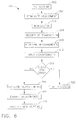
- a specific embodiment of a method that uses system 10 for verifying the correct selection of a machining tool is illustrated by a flowchart shown in FIG. 6 , with the method/system being indicated generally as 300.
- Machining tool program 36 associated with machine 18 may initially position and/or orient tool 26, as indicated by step 302, and then terminate the positioning/orientation adjustment, as indicated by step 304.
- a transaction 40 (which may include a transaction ID, known tool characteristics, identity of tool, etc.) containing the characteristics and measurements of tool 26 that are to be obtained is transmitted to smart camera 34, as indicated by step 306.
- Smart camera 34 receives transmitted transaction 40, as indicated by step 308, and performs the measurements of the characteristics contained in transaction 40, as indicated by step 310, to obtain acquired data 46.
- acquired data 46 is transmitted to tool program 36, as indicated by step 312, where the acquired data 46 may be checked by tool program 36 for an error code, as indicated by step 314. If there is no error code discovered in step 314, the acquired data may be evaluated, etc., by tool program 36, as indicated by step 316, and then used by tool program 36 to control the operation of machine 18, for example, by initially making required adjustments to the position and/or orientation of tool 26, as indicated by step 318. After adjustments are made in step 318, machine 18 may then proceed to have tool 26 perform a machining operation, for example, cutting, as indicated by step 320.
- tool program 36 may halt or terminate, the use of tool 26 and the operation of machine as indicated by step 322, until the discovered error is corrected or otherwise resolved appropriately.
- FIG. 6 shows an illustrative embodiment of method/system 300, it should be understood that the order/sequence of steps may be deleted, changed, altered, modified, etc., as needed, and that additional steps (e.g., re-measurements, etc.) may also be included in method/system 300.
- FIGS. 7-9 An embodiment of a smart camera 34 and associated components that may be used herein is illustrated in FIGS. 7-9 .
- smart camera 34 may be enclosed within a sealed case 402 to protect smart camera 34 and lens 404 thereof from environmental contaminants that might degrade components of smart camera 34.
- the camera 34 may mounted, for example, on 3-point mounting plate which may move within a horizontal and/or vertical slot (not shown) in the bottom of case 402 to provide the ability to adjust the mounting angle and position of smart camera 34.
- a light 410 may be positioned between window 414 and lens 404 to provide illumination for smart camera 34.
- An air inlet 416 may be positioned proximate smart camera 34 for providing air flow to cool the area enclosed by case 402.
- heat generated by light 410 may also be expelled through air outlet 418.
- a conduit 422 may be provided in case 402 for access to smart camera 34 and the other components within case 402.
- An air curtain 424 may also be positioned in front of window 414 to keep debris and other foreign objects off of window 414.
Landscapes
- Engineering & Computer Science (AREA)
- Mechanical Engineering (AREA)
- Physics & Mathematics (AREA)
- Computer Vision & Pattern Recognition (AREA)
- Radar, Positioning & Navigation (AREA)
- Remote Sensing (AREA)
- Electromagnetism (AREA)
- Optics & Photonics (AREA)
- Numerical Control (AREA)
- Machine Tool Sensing Apparatuses (AREA)
Priority Applications (1)
| Application Number | Priority Date | Filing Date | Title |
|---|---|---|---|
| EP07108988A EP2000869A1 (de) | 2007-05-25 | 2007-05-25 | System und Verfahren zum Messen von Maschinenwerkzeugen mit einer Kamera |
Applications Claiming Priority (1)
| Application Number | Priority Date | Filing Date | Title |
|---|---|---|---|
| EP07108988A EP2000869A1 (de) | 2007-05-25 | 2007-05-25 | System und Verfahren zum Messen von Maschinenwerkzeugen mit einer Kamera |
Publications (1)
| Publication Number | Publication Date |
|---|---|
| EP2000869A1 true EP2000869A1 (de) | 2008-12-10 |
Family
ID=38626989
Family Applications (1)
| Application Number | Title | Priority Date | Filing Date |
|---|---|---|---|
| EP07108988A Ceased EP2000869A1 (de) | 2007-05-25 | 2007-05-25 | System und Verfahren zum Messen von Maschinenwerkzeugen mit einer Kamera |
Country Status (1)
| Country | Link |
|---|---|
| EP (1) | EP2000869A1 (de) |
Cited By (5)
| Publication number | Priority date | Publication date | Assignee | Title |
|---|---|---|---|---|
| FR2952196A1 (fr) * | 2009-11-04 | 2011-05-06 | Snecma | Procede de controle d'un outil par vision a l'aide d'une camera telecentrique |
| ITBO20120221A1 (it) * | 2012-04-20 | 2013-10-21 | Marposs Spa | Metodo per posizionare un utensile di una macchina utensile nel campo visivo di un sistema di visione e relativa macchina utensile |
| CN106094727A (zh) * | 2016-06-24 | 2016-11-09 | 廖兴池 | 一种数控机床控制系统及方法 |
| CN113778018A (zh) * | 2021-08-25 | 2021-12-10 | 西安交通大学 | 一种基于R-test的五轴机床刀轴矢量误差测量方法 |
| TWI814991B (zh) * | 2019-03-12 | 2023-09-11 | 日商迪思科股份有限公司 | 監視系統 |
Citations (5)
| Publication number | Priority date | Publication date | Assignee | Title |
|---|---|---|---|---|
| EP0395470A1 (de) * | 1989-04-14 | 1990-10-31 | AEROSPATIALE Société Nationale Industrielle | Werkzeugbruch-Ueberwachungssystem für ein Bearbeitungszentrum |
| US5871391A (en) * | 1980-03-27 | 1999-02-16 | Sensor Adaptive Machine Inc. | Apparatus for determining dimensions |
| EP0976508A2 (de) * | 1998-07-30 | 2000-02-02 | Heinz Gaubatz | Werkstückauflageflache für eine Schneidvorrichtung |
| DE19937265A1 (de) * | 1998-08-07 | 2000-02-10 | Brown & Sharpe Dea Spa | Verfahren und Vorrichtung zur Positionierung eines Meßkopfes auf einer kontaktfreien dreidimensionalen Meßmaschine |
| US20020003415A1 (en) * | 2000-07-10 | 2002-01-10 | Satoru Nakai | Machine tool |
-
2007
- 2007-05-25 EP EP07108988A patent/EP2000869A1/de not_active Ceased
Patent Citations (5)
| Publication number | Priority date | Publication date | Assignee | Title |
|---|---|---|---|---|
| US5871391A (en) * | 1980-03-27 | 1999-02-16 | Sensor Adaptive Machine Inc. | Apparatus for determining dimensions |
| EP0395470A1 (de) * | 1989-04-14 | 1990-10-31 | AEROSPATIALE Société Nationale Industrielle | Werkzeugbruch-Ueberwachungssystem für ein Bearbeitungszentrum |
| EP0976508A2 (de) * | 1998-07-30 | 2000-02-02 | Heinz Gaubatz | Werkstückauflageflache für eine Schneidvorrichtung |
| DE19937265A1 (de) * | 1998-08-07 | 2000-02-10 | Brown & Sharpe Dea Spa | Verfahren und Vorrichtung zur Positionierung eines Meßkopfes auf einer kontaktfreien dreidimensionalen Meßmaschine |
| US20020003415A1 (en) * | 2000-07-10 | 2002-01-10 | Satoru Nakai | Machine tool |
Non-Patent Citations (1)
| Title |
|---|
| MOTAVALLI S ET AL: "AUTOMATED TOOL MONITORING SYSTEM USING VISION SYSTEM FOR A ROBOTIC CELL", ROBOTICS AND COMPUTER INTEGRATED MANUFACTURING, ELSEVIER SCIENCE PUBLISHERS BV., BARKING, GB, vol. 10, no. 4, 1 August 1993 (1993-08-01), pages 311 - 319, XP000387717, ISSN: 0736-5845 * |
Cited By (8)
| Publication number | Priority date | Publication date | Assignee | Title |
|---|---|---|---|---|
| FR2952196A1 (fr) * | 2009-11-04 | 2011-05-06 | Snecma | Procede de controle d'un outil par vision a l'aide d'une camera telecentrique |
| ITBO20120221A1 (it) * | 2012-04-20 | 2013-10-21 | Marposs Spa | Metodo per posizionare un utensile di una macchina utensile nel campo visivo di un sistema di visione e relativa macchina utensile |
| WO2013156575A1 (en) * | 2012-04-20 | 2013-10-24 | Marposs Societa' Per Azioni | Method for positioning a tool of a machine tool in the visual field of a visual system and relative machine tool |
| CN104246634A (zh) * | 2012-04-20 | 2014-12-24 | 马波斯S.P.A.公司 | 用于将工具机的工具定位在视觉系统的视觉范围内的方法及其相关工具机 |
| JP2015518213A (ja) * | 2012-04-20 | 2015-06-25 | マーポス、ソチエタ、ペル、アツィオーニMarposs S.P.A. | 視覚システムの視野内において工作機械の工具を位置決めするための方法、及び、関連する工作機械 |
| CN106094727A (zh) * | 2016-06-24 | 2016-11-09 | 廖兴池 | 一种数控机床控制系统及方法 |
| TWI814991B (zh) * | 2019-03-12 | 2023-09-11 | 日商迪思科股份有限公司 | 監視系統 |
| CN113778018A (zh) * | 2021-08-25 | 2021-12-10 | 西安交通大学 | 一种基于R-test的五轴机床刀轴矢量误差测量方法 |
Similar Documents
| Publication | Publication Date | Title |
|---|---|---|
| US11229965B2 (en) | System and method for automated machining of toothed members | |
| DE3530576C2 (de) | Verfahren und Vorrichtung zum Bestimmen der Abmessungen eines Werkstücks | |
| CN105785943B (zh) | 补偿误差的方法、单元、系统、测量设施、介质 | |
| US8893387B2 (en) | Method for producing a dental shaped part | |
| EP0545658B1 (de) | Automatisiertes Wartungsverfahren für digitale numerisch gesteuerte Maschinen | |
| US6796048B2 (en) | Method, system and storage medium for providing a tool kit for a coordinate measurement system | |
| EP2000869A1 (de) | System und Verfahren zum Messen von Maschinenwerkzeugen mit einer Kamera | |
| EP2302476A9 (de) | Verfahren, System und Speichermedium zur Bereitstellung eines ausführbaren Programms für ein Koordinatenmesssystem | |
| US20130072088A1 (en) | Apparatus and method for working an optical lens and also a transporting containing for optical lenses | |
| CN110168457A (zh) | 生产管理系统以及生产管理方法 | |
| JP7019396B2 (ja) | 工作機械の制御方法、工作機械の制御装置、工作機械の設定支援装置、工作機械の制御システム及びプログラム | |
| US20070198123A1 (en) | System and method for measuring machining tools and using data generated therefrom | |
| CN117806231B (zh) | 一种基于物联网的机床运行加工控制系统及方法 | |
| DE102007016502B4 (de) | Messverfahren und Messsystem zum Vermessen von Werkzeugen | |
| CN117681046A (zh) | 对工具或完整工具进行测定的装置和创建工具或完整工具的数字图像的方法 | |
| JP2008296301A (ja) | 機械加工ツールを測定し、そこから生成されたデータを使用するシステムおよび方法 | |
| KR101896291B1 (ko) | 공작 기계의 가공경로 보정방법 | |
| CN105058169A (zh) | 一种铣刀检测机 | |
| CN120445121A (zh) | 一种非标模架批量成型方法及系统 | |
| US20230205162A1 (en) | Tool part, system, method, and a computer program for determining a dimension of the tool part | |
| CN119159380A (zh) | 一种齿轮加工机床带曲面检测的齿轮加工设备及方法 | |
| KR101621109B1 (ko) | 기계 커터의 시험 방법 | |
| EP3855263A1 (de) | Verfahren und system zum anfasen eines zahnrades | |
| JP6767786B2 (ja) | 測定支援システム及び測定支援方法 | |
| JPH0740172A (ja) | 刃付けされる工具およびこの工具の使用方法 |
Legal Events
| Date | Code | Title | Description |
|---|---|---|---|
| PUAI | Public reference made under article 153(3) epc to a published international application that has entered the european phase |
Free format text: ORIGINAL CODE: 0009012 |
|
| AK | Designated contracting states |
Kind code of ref document: A1 Designated state(s): AT BE BG CH CY CZ DE DK EE ES FI FR GB GR HU IE IS IT LI LT LU LV MC MT NL PL PT RO SE SI SK TR |
|
| AX | Request for extension of the european patent |
Extension state: AL BA HR MK RS |
|
| 17P | Request for examination filed |
Effective date: 20090610 |
|
| 17Q | First examination report despatched |
Effective date: 20090714 |
|
| AKX | Designation fees paid |
Designated state(s): DE FR GB IT |
|
| STAA | Information on the status of an ep patent application or granted ep patent |
Free format text: STATUS: THE APPLICATION HAS BEEN REFUSED |
|
| 18R | Application refused |
Effective date: 20110418 |