EP2000734A2 - Pressure-resistant vessel - Google Patents
Pressure-resistant vessel Download PDFInfo
- Publication number
- EP2000734A2 EP2000734A2 EP07739075A EP07739075A EP2000734A2 EP 2000734 A2 EP2000734 A2 EP 2000734A2 EP 07739075 A EP07739075 A EP 07739075A EP 07739075 A EP07739075 A EP 07739075A EP 2000734 A2 EP2000734 A2 EP 2000734A2
- Authority
- EP
- European Patent Office
- Prior art keywords
- pressure
- ring
- mouth ring
- container
- pressing member
- Prior art date
- Legal status (The legal status is an assumption and is not a legal conclusion. Google has not performed a legal analysis and makes no representation as to the accuracy of the status listed.)
- Granted
Links
Images


Classifications
-
- F—MECHANICAL ENGINEERING; LIGHTING; HEATING; WEAPONS; BLASTING
- F16—ENGINEERING ELEMENTS AND UNITS; GENERAL MEASURES FOR PRODUCING AND MAINTAINING EFFECTIVE FUNCTIONING OF MACHINES OR INSTALLATIONS; THERMAL INSULATION IN GENERAL
- F16J—PISTONS; CYLINDERS; SEALINGS
- F16J13/00—Covers or similar closure members for pressure vessels in general
- F16J13/02—Detachable closure members; Means for tightening closures
- F16J13/12—Detachable closure members; Means for tightening closures attached by wedging action by means of screw-thread, interrupted screw-thread, bayonet closure, or the like
-
- F—MECHANICAL ENGINEERING; LIGHTING; HEATING; WEAPONS; BLASTING
- F17—STORING OR DISTRIBUTING GASES OR LIQUIDS
- F17C—VESSELS FOR CONTAINING OR STORING COMPRESSED, LIQUEFIED OR SOLIDIFIED GASES; FIXED-CAPACITY GAS-HOLDERS; FILLING VESSELS WITH, OR DISCHARGING FROM VESSELS, COMPRESSED, LIQUEFIED, OR SOLIDIFIED GASES
- F17C13/00—Details of vessels or of the filling or discharging of vessels
- F17C13/06—Closures, e.g. cap, breakable member
-
- F—MECHANICAL ENGINEERING; LIGHTING; HEATING; WEAPONS; BLASTING
- F17—STORING OR DISTRIBUTING GASES OR LIQUIDS
- F17C—VESSELS FOR CONTAINING OR STORING COMPRESSED, LIQUEFIED OR SOLIDIFIED GASES; FIXED-CAPACITY GAS-HOLDERS; FILLING VESSELS WITH, OR DISCHARGING FROM VESSELS, COMPRESSED, LIQUEFIED, OR SOLIDIFIED GASES
- F17C2201/00—Vessel construction, in particular geometry, arrangement or size
- F17C2201/01—Shape
- F17C2201/0104—Shape cylindrical
- F17C2201/0109—Shape cylindrical with exteriorly curved end-piece
-
- F—MECHANICAL ENGINEERING; LIGHTING; HEATING; WEAPONS; BLASTING
- F17—STORING OR DISTRIBUTING GASES OR LIQUIDS
- F17C—VESSELS FOR CONTAINING OR STORING COMPRESSED, LIQUEFIED OR SOLIDIFIED GASES; FIXED-CAPACITY GAS-HOLDERS; FILLING VESSELS WITH, OR DISCHARGING FROM VESSELS, COMPRESSED, LIQUEFIED, OR SOLIDIFIED GASES
- F17C2203/00—Vessel construction, in particular walls or details thereof
- F17C2203/06—Materials for walls or layers thereof; Properties or structures of walls or their materials
- F17C2203/0602—Wall structures; Special features thereof
- F17C2203/0612—Wall structures
- F17C2203/0614—Single wall
- F17C2203/0619—Single wall with two layers
-
- F—MECHANICAL ENGINEERING; LIGHTING; HEATING; WEAPONS; BLASTING
- F17—STORING OR DISTRIBUTING GASES OR LIQUIDS
- F17C—VESSELS FOR CONTAINING OR STORING COMPRESSED, LIQUEFIED OR SOLIDIFIED GASES; FIXED-CAPACITY GAS-HOLDERS; FILLING VESSELS WITH, OR DISCHARGING FROM VESSELS, COMPRESSED, LIQUEFIED, OR SOLIDIFIED GASES
- F17C2203/00—Vessel construction, in particular walls or details thereof
- F17C2203/06—Materials for walls or layers thereof; Properties or structures of walls or their materials
- F17C2203/0634—Materials for walls or layers thereof
- F17C2203/0658—Synthetics
- F17C2203/066—Plastics
-
- F—MECHANICAL ENGINEERING; LIGHTING; HEATING; WEAPONS; BLASTING
- F17—STORING OR DISTRIBUTING GASES OR LIQUIDS
- F17C—VESSELS FOR CONTAINING OR STORING COMPRESSED, LIQUEFIED OR SOLIDIFIED GASES; FIXED-CAPACITY GAS-HOLDERS; FILLING VESSELS WITH, OR DISCHARGING FROM VESSELS, COMPRESSED, LIQUEFIED, OR SOLIDIFIED GASES
- F17C2203/00—Vessel construction, in particular walls or details thereof
- F17C2203/06—Materials for walls or layers thereof; Properties or structures of walls or their materials
- F17C2203/0634—Materials for walls or layers thereof
- F17C2203/0658—Synthetics
- F17C2203/0663—Synthetics in form of fibers or filaments
-
- F—MECHANICAL ENGINEERING; LIGHTING; HEATING; WEAPONS; BLASTING
- F17—STORING OR DISTRIBUTING GASES OR LIQUIDS
- F17C—VESSELS FOR CONTAINING OR STORING COMPRESSED, LIQUEFIED OR SOLIDIFIED GASES; FIXED-CAPACITY GAS-HOLDERS; FILLING VESSELS WITH, OR DISCHARGING FROM VESSELS, COMPRESSED, LIQUEFIED, OR SOLIDIFIED GASES
- F17C2205/00—Vessel construction, in particular mounting arrangements, attachments or identifications means
- F17C2205/03—Fluid connections, filters, valves, closure means or other attachments
- F17C2205/0302—Fittings, valves, filters, or components in connection with the gas storage device
- F17C2205/0305—Bosses, e.g. boss collars
-
- F—MECHANICAL ENGINEERING; LIGHTING; HEATING; WEAPONS; BLASTING
- F17—STORING OR DISTRIBUTING GASES OR LIQUIDS
- F17C—VESSELS FOR CONTAINING OR STORING COMPRESSED, LIQUEFIED OR SOLIDIFIED GASES; FIXED-CAPACITY GAS-HOLDERS; FILLING VESSELS WITH, OR DISCHARGING FROM VESSELS, COMPRESSED, LIQUEFIED, OR SOLIDIFIED GASES
- F17C2205/00—Vessel construction, in particular mounting arrangements, attachments or identifications means
- F17C2205/03—Fluid connections, filters, valves, closure means or other attachments
- F17C2205/0302—Fittings, valves, filters, or components in connection with the gas storage device
- F17C2205/0311—Closure means
-
- F—MECHANICAL ENGINEERING; LIGHTING; HEATING; WEAPONS; BLASTING
- F17—STORING OR DISTRIBUTING GASES OR LIQUIDS
- F17C—VESSELS FOR CONTAINING OR STORING COMPRESSED, LIQUEFIED OR SOLIDIFIED GASES; FIXED-CAPACITY GAS-HOLDERS; FILLING VESSELS WITH, OR DISCHARGING FROM VESSELS, COMPRESSED, LIQUEFIED, OR SOLIDIFIED GASES
- F17C2209/00—Vessel construction, in particular methods of manufacturing
- F17C2209/21—Shaping processes
- F17C2209/2109—Moulding
- F17C2209/2127—Moulding by blowing
-
- F—MECHANICAL ENGINEERING; LIGHTING; HEATING; WEAPONS; BLASTING
- F17—STORING OR DISTRIBUTING GASES OR LIQUIDS
- F17C—VESSELS FOR CONTAINING OR STORING COMPRESSED, LIQUEFIED OR SOLIDIFIED GASES; FIXED-CAPACITY GAS-HOLDERS; FILLING VESSELS WITH, OR DISCHARGING FROM VESSELS, COMPRESSED, LIQUEFIED, OR SOLIDIFIED GASES
- F17C2209/00—Vessel construction, in particular methods of manufacturing
- F17C2209/21—Shaping processes
- F17C2209/2154—Winding
-
- F—MECHANICAL ENGINEERING; LIGHTING; HEATING; WEAPONS; BLASTING
- F17—STORING OR DISTRIBUTING GASES OR LIQUIDS
- F17C—VESSELS FOR CONTAINING OR STORING COMPRESSED, LIQUEFIED OR SOLIDIFIED GASES; FIXED-CAPACITY GAS-HOLDERS; FILLING VESSELS WITH, OR DISCHARGING FROM VESSELS, COMPRESSED, LIQUEFIED, OR SOLIDIFIED GASES
- F17C2209/00—Vessel construction, in particular methods of manufacturing
- F17C2209/22—Assembling processes
- F17C2209/221—Welding
-
- F—MECHANICAL ENGINEERING; LIGHTING; HEATING; WEAPONS; BLASTING
- F17—STORING OR DISTRIBUTING GASES OR LIQUIDS
- F17C—VESSELS FOR CONTAINING OR STORING COMPRESSED, LIQUEFIED OR SOLIDIFIED GASES; FIXED-CAPACITY GAS-HOLDERS; FILLING VESSELS WITH, OR DISCHARGING FROM VESSELS, COMPRESSED, LIQUEFIED, OR SOLIDIFIED GASES
- F17C2209/00—Vessel construction, in particular methods of manufacturing
- F17C2209/22—Assembling processes
- F17C2209/227—Assembling processes by adhesive means
-
- F—MECHANICAL ENGINEERING; LIGHTING; HEATING; WEAPONS; BLASTING
- F17—STORING OR DISTRIBUTING GASES OR LIQUIDS
- F17C—VESSELS FOR CONTAINING OR STORING COMPRESSED, LIQUEFIED OR SOLIDIFIED GASES; FIXED-CAPACITY GAS-HOLDERS; FILLING VESSELS WITH, OR DISCHARGING FROM VESSELS, COMPRESSED, LIQUEFIED, OR SOLIDIFIED GASES
- F17C2209/00—Vessel construction, in particular methods of manufacturing
- F17C2209/22—Assembling processes
- F17C2209/228—Assembling processes by screws, bolts or rivets
-
- F—MECHANICAL ENGINEERING; LIGHTING; HEATING; WEAPONS; BLASTING
- F17—STORING OR DISTRIBUTING GASES OR LIQUIDS
- F17C—VESSELS FOR CONTAINING OR STORING COMPRESSED, LIQUEFIED OR SOLIDIFIED GASES; FIXED-CAPACITY GAS-HOLDERS; FILLING VESSELS WITH, OR DISCHARGING FROM VESSELS, COMPRESSED, LIQUEFIED, OR SOLIDIFIED GASES
- F17C2209/00—Vessel construction, in particular methods of manufacturing
- F17C2209/23—Manufacturing of particular parts or at special locations
- F17C2209/234—Manufacturing of particular parts or at special locations of closing end pieces, e.g. caps
-
- F—MECHANICAL ENGINEERING; LIGHTING; HEATING; WEAPONS; BLASTING
- F17—STORING OR DISTRIBUTING GASES OR LIQUIDS
- F17C—VESSELS FOR CONTAINING OR STORING COMPRESSED, LIQUEFIED OR SOLIDIFIED GASES; FIXED-CAPACITY GAS-HOLDERS; FILLING VESSELS WITH, OR DISCHARGING FROM VESSELS, COMPRESSED, LIQUEFIED, OR SOLIDIFIED GASES
- F17C2221/00—Handled fluid, in particular type of fluid
- F17C2221/01—Pure fluids
- F17C2221/012—Hydrogen
-
- F—MECHANICAL ENGINEERING; LIGHTING; HEATING; WEAPONS; BLASTING
- F17—STORING OR DISTRIBUTING GASES OR LIQUIDS
- F17C—VESSELS FOR CONTAINING OR STORING COMPRESSED, LIQUEFIED OR SOLIDIFIED GASES; FIXED-CAPACITY GAS-HOLDERS; FILLING VESSELS WITH, OR DISCHARGING FROM VESSELS, COMPRESSED, LIQUEFIED, OR SOLIDIFIED GASES
- F17C2221/00—Handled fluid, in particular type of fluid
- F17C2221/03—Mixtures
- F17C2221/032—Hydrocarbons
- F17C2221/033—Methane, e.g. natural gas, CNG, LNG, GNL, GNC, PLNG
-
- F—MECHANICAL ENGINEERING; LIGHTING; HEATING; WEAPONS; BLASTING
- F17—STORING OR DISTRIBUTING GASES OR LIQUIDS
- F17C—VESSELS FOR CONTAINING OR STORING COMPRESSED, LIQUEFIED OR SOLIDIFIED GASES; FIXED-CAPACITY GAS-HOLDERS; FILLING VESSELS WITH, OR DISCHARGING FROM VESSELS, COMPRESSED, LIQUEFIED, OR SOLIDIFIED GASES
- F17C2223/00—Handled fluid before transfer, i.e. state of fluid when stored in the vessel or before transfer from the vessel
- F17C2223/01—Handled fluid before transfer, i.e. state of fluid when stored in the vessel or before transfer from the vessel characterised by the phase
- F17C2223/0146—Two-phase
- F17C2223/0153—Liquefied gas, e.g. LPG, GPL
- F17C2223/0161—Liquefied gas, e.g. LPG, GPL cryogenic, e.g. LNG, GNL, PLNG
-
- F—MECHANICAL ENGINEERING; LIGHTING; HEATING; WEAPONS; BLASTING
- F17—STORING OR DISTRIBUTING GASES OR LIQUIDS
- F17C—VESSELS FOR CONTAINING OR STORING COMPRESSED, LIQUEFIED OR SOLIDIFIED GASES; FIXED-CAPACITY GAS-HOLDERS; FILLING VESSELS WITH, OR DISCHARGING FROM VESSELS, COMPRESSED, LIQUEFIED, OR SOLIDIFIED GASES
- F17C2223/00—Handled fluid before transfer, i.e. state of fluid when stored in the vessel or before transfer from the vessel
- F17C2223/03—Handled fluid before transfer, i.e. state of fluid when stored in the vessel or before transfer from the vessel characterised by the pressure level
- F17C2223/033—Small pressure, e.g. for liquefied gas
-
- F—MECHANICAL ENGINEERING; LIGHTING; HEATING; WEAPONS; BLASTING
- F17—STORING OR DISTRIBUTING GASES OR LIQUIDS
- F17C—VESSELS FOR CONTAINING OR STORING COMPRESSED, LIQUEFIED OR SOLIDIFIED GASES; FIXED-CAPACITY GAS-HOLDERS; FILLING VESSELS WITH, OR DISCHARGING FROM VESSELS, COMPRESSED, LIQUEFIED, OR SOLIDIFIED GASES
- F17C2260/00—Purposes of gas storage and gas handling
- F17C2260/01—Improving mechanical properties or manufacturing
- F17C2260/011—Improving strength
-
- F—MECHANICAL ENGINEERING; LIGHTING; HEATING; WEAPONS; BLASTING
- F17—STORING OR DISTRIBUTING GASES OR LIQUIDS
- F17C—VESSELS FOR CONTAINING OR STORING COMPRESSED, LIQUEFIED OR SOLIDIFIED GASES; FIXED-CAPACITY GAS-HOLDERS; FILLING VESSELS WITH, OR DISCHARGING FROM VESSELS, COMPRESSED, LIQUEFIED, OR SOLIDIFIED GASES
- F17C2260/00—Purposes of gas storage and gas handling
- F17C2260/03—Dealing with losses
- F17C2260/035—Dealing with losses of fluid
- F17C2260/036—Avoiding leaks
-
- F—MECHANICAL ENGINEERING; LIGHTING; HEATING; WEAPONS; BLASTING
- F17—STORING OR DISTRIBUTING GASES OR LIQUIDS
- F17C—VESSELS FOR CONTAINING OR STORING COMPRESSED, LIQUEFIED OR SOLIDIFIED GASES; FIXED-CAPACITY GAS-HOLDERS; FILLING VESSELS WITH, OR DISCHARGING FROM VESSELS, COMPRESSED, LIQUEFIED, OR SOLIDIFIED GASES
- F17C2270/00—Applications
- F17C2270/01—Applications for fluid transport or storage
- F17C2270/0165—Applications for fluid transport or storage on the road
- F17C2270/0168—Applications for fluid transport or storage on the road by vehicles
-
- Y—GENERAL TAGGING OF NEW TECHNOLOGICAL DEVELOPMENTS; GENERAL TAGGING OF CROSS-SECTIONAL TECHNOLOGIES SPANNING OVER SEVERAL SECTIONS OF THE IPC; TECHNICAL SUBJECTS COVERED BY FORMER USPC CROSS-REFERENCE ART COLLECTIONS [XRACs] AND DIGESTS
- Y02—TECHNOLOGIES OR APPLICATIONS FOR MITIGATION OR ADAPTATION AGAINST CLIMATE CHANGE
- Y02E—REDUCTION OF GREENHOUSE GAS [GHG] EMISSIONS, RELATED TO ENERGY GENERATION, TRANSMISSION OR DISTRIBUTION
- Y02E60/00—Enabling technologies; Technologies with a potential or indirect contribution to GHG emissions mitigation
- Y02E60/30—Hydrogen technology
- Y02E60/32—Hydrogen storage
Definitions
- the present invention relates to a pressure-resistant container in which an inner shell made of a resin is covered with an outer shell made of a fiber reinforced composite material.
- nonpolluting automobiles have been developed, and a part of them has been put to practical use with the aim of preventing an environmental deterioration caused by the exhaust gas of automobiles.
- an automobile operating by means of a natural gas in which methane is the main component as the fuel has been authorized as a low pollution automobile, and about one million units of the automobiles have been actually used already all over the world.
- a fuel cell powered automobile using hydrogen as its fuel will substitute for most of the current gasoline-driven automobiles in the future.
- the natural gas and hydrogen that are used here are compressed natural gas and compressed hydrogen, respectively, and it is thought that the pressures will be ultrahigh pressures, such as 20 MPa to 25 MPa for the natural gas and 35 MPa to 70 MPa for hydrogen. Consequently, a tank (pressure-resistant container) having a pressure-resistant performance is needed, and a high pressure tank made of steel has been used conventionally.
- the tanks to be mounted are light weighted from the point of view of the improvement of engine performance, the improvement of fuel consumption and the like.
- a tank made of an aluminum liner which is reinforced with carbon fibers has been used as an alternative for the steel tank.
- a tank using a resin liner in which the entire tank is made of resin has been developed in order to achieve further lightweight (for example, Patent Document 1).
- the tank made of resin liner is a gas tank composed of a resin inner shell (inner wall) having a gas barrier property and a fiber reinforced plastic (FRP) outer shell (outer wall) having a pressure resistance property wherein the outer shell covers the inner shell, and is lighter than a metal tank because the tank made of resin liner is mainly made of resin.
- This sort of gas tank is provided with a nozzle attaching mouth ring in order to attach a nozzle for filling a gas into the tank and for taking the gas out from the tank.
- the mouth ring portion is generally joined with the inner shell integrally.
- the mouth ring portion for screwing the nozzle or the like is generally made of a metal, and the inner shell is made of a material (the above mentioned resin, FRP or a light metal) different from that of the mouth ring portion from the point of view of the weight saving or the simplification of the manufacturing process. Because the mouth ring portion and the inner shell which are made of different materials from each other are integrally joined, the sealing property of the joined part or the interface part of the inner shell and the mouth ring portion becomes important.
- the gas tank which is called the above mentioned high pressure natural gas tank or high pressure hydrogen gas tank for an automobile
- an extremely high gas sealing property is required.
- the conventional gas tank yet has insufficient gas sealing property of the joined part or the interface part of the inner shell and the mouth ring portion.
- Patent Documents 2 to 5 propose pressure-resistant containers having improved gas sealing property of the mouth ring portion in the high pressure gas tanks made of resin.
- the pressure-resistant container described in Patent Document 2 has the structure of enhancing the gas sealing property of the mouth ring portion by adopting the structure of receiving a disk-like flange part of the mouth ring portion with upper and lower lips at the end part of the inner shell.
- the end part of the mouth ring is exposed to its internal gas, and the internal pressure of the gas is directly applied to the end part of the mouth ring portion. Consequently, even when gas leakage does not occur just after the manufacturing of the pressure-resistant container, creeping occurs in the resin of the inner shell to shrink and a gap is generated at an interface of the inner shell and the mouth ring while using the container for a long time. Thus, there is a possibility that gas leakage might occur from the gap at the interface.
- the pressure-resistant container is structured so as to oppose the force which tears off both the lips with the locking groove, which force is a shearing force operates on both the lip parts joined to the locking groove at the upper and lower surfaces of the disk-like flange when the inner shell swells at the time of the swelling of the container by an internal pressure when a high pressure gas is kept in the pressure-resistant container.
- the pressure-resistant container described in Patent Document 4 aims to enhance the gas sealing property by adopting the following structure: the mouth ring intervenes at the inner side of the opening part of the inner shell manufactured by the blow molding; a sealing ring made of rubber or the like is fitted to the shoulder part of the inner shell; the sealing ring is pressed by a pressing member made of a metal or the like; and filament winding molding is performed thereover.
- the pressing member of the sealing ring is made of a metal
- the fitting part of the sealing ring is only structured with the resin-made inner shell. Therefore, even when a gas leakage does not occur right after the manufacturing of the pressure-resistant container, the plastic of the inner shell creeps and the inner shell shrinks while the container is being used for a long time.
- the pressure-resistant container described in Patent Document 5 also has the following problem. That is, even when one side is the pressing member made of metal which can easily secure its surface accuracy, the other side is made of plastic which cannot secure its surface accuracy. Consequently, this structure lacks the reliability of sealing. Moreover, in order to embed the edge part of the inner shell into the mouth ring in a shape of being bent outside, the mouth ring is needed to be set in a centrifugal mold and the rotational molding which takes a long time is needed to be used for the molding of the plastic liner of the inner shell, and thereby the lowering of the cost of the inner shell is prevented.
- the end part of the mouth ring is formed so as to project to the inner side.
- the projecting part causes no problem in the case of a relatively low pressure tank.
- the bending strength of the mouth ring at the projecting part by the internal pressure of the tank becomes greater in an ultra high pressure tank, such as 70 MPa, and there is a possibility that the breaking of the mouth ring occurs in a repetition cycle.
- the present invention was completed as the result of a keen examination in order to provide a pressure-resistant container which solves the above several problems at once, and the object of the present invention is to make the manufacturing of the pressure-resistant container in which the inner shell is covered with the outer shell easy and to enhance the gas sealing property at the edge part (interface part) of the covering where the inner shell and the mouth ring adhere to one another.
- the invention of claim 1 for solving the above problem is a pressure-resistant container comprising an inner shell, an outer shell to cover the inner shell, a cylindrical mouth ring to penetrate the outer shell to be connected to an opening formed at the inner shell, a peripheral part of the opening at the inner shell covering an end surface of the mouth ring at an inner side of the container, a cylindrical pressing member screwed into an inner peripheral surface of the mouth ring, a first seal peripherally contacting with the inner peripheral surface of the mouth ring which is exposed between the inner shell and the pressing member and with a periphery of the opening of the inner shell in an integral manner, a valve having a screw part screwed into the inner peripheral surface of the mouth ring at an outer side of the container than the pressing member and having an inner end part inserted into a hole part of the pressing member and a second seal for sealing between an outer peripheral surface of the inner end part and an inner peripheral surface of the pressing member.
- peripheral contacting means contacting with the other material so as to go around the material (the same applies
- the invention according to claim 2 is the pressure-resistant container as claimed in claim 1, wherein the first seal peripherally contacts with the inner peripheral surface of the mouth ring which is exposed between the inner shell and the pressing member, the periphery of the opening of the inner shell and the pressing member in the integral manner.
- the invention according to claim 3 is the pressure-resistant container as claimed in claim 1 or 2, wherein the peripheral part covers a predetermined range of the inner peripheral surface of the mouth ring by peripherally contacting with the predetermined range continuously to the end surface of the mouth ring at the inner side of the container.
- the invention according to claim 4 is the pressure-resistant container as claimed in claim 3, wherein the peripheral part comprises an extending part which extends from a covering part of the predetermined range toward an inner part of the mouth ring, and the first seal peripherally contacts with the extending part.
- the invention according to claim 5 is the pressure-resistant container as claimed in any one of claims 1 to 4, wherein a flange which is sandwiched between the outer shell and the inner shell is formed at an end part of the mouth ring at the inner side of the container.
- the invention according to claim 6 is the pressure-resistant container as claimed in claim 5, wherein the second seal is disposed at an inner side of the container than a joining position of the flange and a cylindrical neck part of the mouth ring.
- the invention according to claim 7 is the pressure-resistant container as claimed in any one of claims 1 to 6, wherein the first seal is a liquid sealant.
- the invention according to claim 8 is the pressure-resistant container as claimed in any one of claims 1 to 6, wherein the first seal is an O-ring and a liquid sealant adhering to the O-ring.
- the invention according to claim 9 is the pressure-resistant container as claimed in any one of claims 1 to 8, wherein a liquid sealant is attached between an outer peripheral surface of the pressing member and the inner peripheral surface of the mouth ring opposed to the outer peripheral surface of the pressing member.
- the invention according to claim 10 is the pressure-resistant container as claimed in any one of claims 1 to 9, wherein a liquid sealant is attached between an end surface of the pressing member at an outer side of the container and the inner peripheral surface of the mouth ring.
- the invention according to claim 11 is the pressure-resistant container as claimed in any one of claims 1 to 10, wherein the second seal is an O-ring.
- the invention according to claim 12 is the pressure-resistant container as claimed in claim 11, wherein a circumferential groove to hold the O-ring of the second seal is formed at an outer peripheral surface of the inner end part.
- the invention according to claim 13 is the pressure-resistant container as claimed in any one of claims 1 to 12, wherein a flange part is provided at an end part of the valve at an outer side of the container, and a third seal is provided to seal a part between the flange part and an end surface of the mouth ring at the outer side of the container.
- the invention according to claim 14 is the pressure-resistant container as claimed in claim 13, wherein the third seal is an O-ring.
- the invention according to claim 15 is the pressure-resistant container as claimed in any one of claims 1 to 14, wherein the inner shell is made of a resin, and the outer shell is made of a composite material of a fiber reinforced resin.
- the second seal seals the part between the outer peripheral surface of the inner end part of the valve and the inner peripheral surface of the pressing member, the internal gas will not go around the end part of the pressing member at the outer side of the container to enter the edge part of the covering where the inner shell and the mouth ring adhere to one another, and consequently the gas sealing property of the edge part of the covering where the inner shell and the mouth ring adhere to one another can be enhanced.
- the effect of realizing the high pressure resistance property of the container is obtained.
- the inner shell because it is sufficient for the inner shell to cover at least the end surface of the mouth ring at the inner side of the container, a molding technique having good productivity, such as the blow molding, can be applied to the inner shell before attaching the mouth ring thereto, and the mouth ring that has been configured separately can be attached to the inner shell by adhesion, welding or the like, after the molding of the inner shell. Consequently, the effect of making the manufacturing of the pressure-resistant container easy to reduce the cost is obtained.
- a molding technique having good productivity such as the blow molding
- FIG. 1 is an outline view of the entire pressure-resistant container according to the first embodiment of the present invention.
- the pressure-resistant container 1 of the present embodiment comprises an outer shell 2 and mouth rings 4.
- the outer shell 2 is made of a composite material of a fiber reinforced resin such as CFRP, and is composed of a cylinder part 2a and dome parts 2b and 2b continuing from both ends of the cylinder part 2a.
- the outer shell 2 covers an inner shell (omitted from the drawing).
- the mouth rings 4 are provided at the peak parts of the dome parts 2b and 2b. Only one mouth ring may be provided.
- FIG. 2 is a sectional view of a mouth ring portion of the pressure-resistant container 1.
- FIG. 3 is a partially enlarged view of FIG. 2 .
- the inner shell 3 is made of a resin and has a gas barrier property. That is, the inner shell 3 is a member to bear the function of a gas barrier in the pressure-resistant container 1.
- the inner shell 3 is made of the resin and it is thin and easy to swell, the pressure resistance of the container is enhanced by the outer shell 2 made of the composite material of the fiber reinforced resin covering the inner shell 3. That is, the outer shell 2 is the member to bear the function of pressure resistance in the pressure-resistant container 1.
- the mouth ring 4 is cylindrical.
- a flange 4a is formed at the end part of the mouth ring 4 at the inner side of the container.
- the peripheral part 3a of the opening 3d of the inner shell 3 covers the end surface of the mouth ring 4 at the inner side of the container (that is, the end surface of the flange 4a at the inner side of the container) by adhesion, welding or the like.
- the circumference of the flange 4a is formed to be sharp, and an inner tapered surface t1 and an outer tapered surface t2 are formed on the end surface of the flange 4a at the inner side of the container.
- the inner shell 3 (peripheral part 3a) covers the inner tapered surface t1 and the outer tapered surface t2 continuously to both of the inner tapered surface t1 and the outer tapered surface t2.
- a cylindrical neck part 3b is formed at a part nearer to the opening 3d than the part of the peripheral part 3a that covers the inner tapered surface t1, and further, an extending part 3c is formed at a part even more nearer to the opening 3d (the peripheral part 3a includes the cylindrical neck part 3d and the extending part 3 c).
- the cylindrical neck part 3b covers a predetermined range n of the inner peripheral surface of the mouth ring 4 by the cylindrical neck part 3b peripherally contacting with the predetermined range.
- the peripheral part 3a covers a predetermined range n of the inner peripheral surface of the mouth ring 4 continuously to the end surface (the inner tapered surface t1 and the outer tapered surface t2) of the mouth ring 4 at the inner side of the container by the peripheral part 3a peripherally contacting with the predetermined range n.
- the extending part 3c is bent at the covered edge part P to extend from the covering part of the predetermined range n to the inner part of the mouth ring 4.
- the inner peripheral surface of the mouth ring 4 has a stepped structure in which the diameter in the outer side of the container is larger.
- a female screw into which the pressing member 5 is screwed is formed at the inner side steps 4b.
- a female screw into which the screw part 6b of the valve 6 is screwed is formed at the outer side steps 4c.
- the pressing member 5 is formed in a simple cylindrical shape and does not have a flange nor a taper.
- a male screw screwed into the inner side steps 4b of the mouth ring 4 is formed at the outer peripheral surface of the pressing member 5.
- the valve 6 has a flange part 6a, the screw part 6b and an inner end part 6c in which the diameters become smaller stepwise toward the inner part of the container in order.
- a male screw screwed into the outer side steps 4c of the mouth ring 4 is formed at the outer peripheral surface of the screw part 6b.
- a circumferential groove 6d to hold an O-ring 12 (second seal) is formed on the outer peripheral surface of the inner end part 6c.
- a gas airway is formed at the valve 6, although it is not shown.
- the pressure-resistant container 1 is manufactured by molding and curing the outer shell 2 by the filament winding method so that the outer shell 2 covers the outside of the inner shell 3 and the flanges 4a of the mouth rings 4, and so that the outer shell 2 makes the end part of the mouth ring 4 at the outer side of the container to project.
- the pressure-resistant container 1 thus has the structure in which the mouth ring 4 protrudes the outer shell 2 (dome part 2b).
- a male screw 4d screwed into a tightening nut 7 is formed at the outer peripheral surface of the end part of the mouth ring 4 projecting to the outer side of the outer shell 2 (dome part 2b).
- the flange 4a is put between the outer shell 2 (dome part 2b) and the inner shell 3. There is nothing between the flange 4a and the outer shell 2 (dome part 2b), and the flange 4a and the outer shell 2 (dome part 2b) contact with each other.
- the pressure-resident container 1 has the above described structure of each portion, and the pressing member 5 is screwed into the inner side steps 4b of the mouth ring 4, the screw part 6b of the valve 6 is screwed into the outer side steps 4c of the mouth ring 4, and the inner end part 6c is inserted into the hole part of the pressing member 5 as shown in FIGS. 2 and 3 .
- the O-ring 12 (second seal) held in the circumferential groove 6d is also disposed in the hole part of the pressing member 5 along with the inner end part 6c being inserted into the hole part of the pressing member 5.
- the O-ring 12 (second seal) seals between the outer peripheral surface of the inner end part 6c and the inner peripheral surface of the pressing member 5.
- the O-ring 12 (second seal) is disposed at a position more in the inner side of the container than a joining position C of the flange 4a and a cylindrical neck part 4e of the mouth ring 4.
- the flange part 6a presses the O-ring 13 (third seal) onto the end surface of the mouth ring 4 at the outer side of the container. Thereby, the space between the flange part 6a and the end surface of the mouth ring 4 at the outer side of the container is sealed.
- the first seal is composed of an O-ring 10 and a liquid sealant 11a.
- the liquid sealant 11 a adheres to the O-ring 10 to cover the O-ring 10.
- the first seal peripherally contacts with an inner peripheral surface b of the mouth ring 4 which is exposed between the inner shell 3 and the pressing member 5. Moreover, the first seal peripherally contacts with the surface of the extending part 3c of the inner shell 3 at the outer side of the container. Furthermore, the first seal peripherally contacts with the surface (O-ring pressing surface) of the pressing member 5 at the inner side of the container.
- the surface of the extending part 3c of the inner shell 3 at the outer side of the container and the surface of the pressing member 5 at the inner side of the container are opposed to each other, and the inner peripheral surface b of the mouth ring 4 is exposed between the above surface of the extending part 3c of the inner shell 3 at the outer side of the container and the surface of the pressing member 5 at the inner side of the container.
- the first seals peripherally contacts with the surface (the surface of the extending part 3c at the outer side of the container in the embodiment) of the inner shell 3 adjacent to the inner peripheral surface b.
- the first seal peripherally contacts with each part of the inner peripheral surface b of the mouth ring 4 exposed between the inner shell 3 and the pressing member 5, the periphery of the opening 3d of the inner shell 3 adjacent to the inner peripheral surface b and the pressing member 5 in an integral manner.
- the liquid sealant 11a of the first seal always peripherally contacts with the above mentioned three surfaces.
- a liquid sealant 11b is attached between the outer peripheral surface of the pressing member 5 and the inner peripheral surface (the inner side steps 4b) of the mouth ring 4 opposed to the outer peripheral surface of the pressing member 5 in order to perform a greater sealing.
- a liquid sealant 11c is attached between the surface of the pressing member 5 at the outer side of the container and the inner peripheral surface (the inner side step 4b) of the mouth ring 4.
- the mouth ring 4 and the inner shell 3 are joined to each other by adhesion or welding.
- the area of the flange 4a of the mouth ring 4 has an aspect of being determined by the factor of the strength thereof. However, the area is determined mainly for securing the joining area of the inner shell 3 and the mouth ring 4 wherein the joining area is needed as a seal. Consequently, sufficient sealing can be carried out by the adhesion or the welding.
- the resin inner shell 3 has sufficient flexibility comparing to the composite material, such as CFRP, of the outer shell 2, the inner shell 3 is pressed to the mouth ring 4 by the internal pressure of the tank, and thereby, the sealing property is improved.
- a high pressure gas G is filled in the inner side of the first and second seals. It is important not to expose the covered edge parts P of the inner shell 3 and the mouth ring 4 to the internal gas in order to keep the sealing property in a good condition. When the covered edge part P is exposed to the internal gas, then the interfacial peeling or the like of the inner shell 3 and the mouth ring 4 from the covered edge part P occurs by the pressure of the internal gas, and there is a possibility that a gas leakage occurs.
- the O-ring 10 which is loaded with a pressure by the high pressure gas G deforms so as to enlarge its diameter, and the O-ring 10 contacts with the inner peripheral surface b of the mouth ring 4 by a pressure. Moreover, the O-ring 10 loaded with the pressure by the high pressure gas G deforms in its cross section, and the O-ring 10 contact with the surface of the pressing member 5 at the inner side of the container and the extending part 3c of the inner shell 3 to adhere closely to both of them in larger area. In this way, the sealing property of the container is enhanced by the O-ring 10 when a high presser is load.
- the valve 6 is secured by the screwing of the screw part 6b of the valve 6 into the female screw of the mouth ring 4 at the outer side steps 4c.
- the O-ring 12 is held in the circumferential groove at the inner end part 6c, and sealing is carried out between the inner end part 6c and the surface of the pressing member 5 at the inner side. Because the pressing member 5 (ring) can be manufactured with high accuracy by a machining process, the surface accuracy necessary for sealing can be easily secured.
- the O-ring 12 which is loaded with a pressure by the high pressure gas G causes a deformation in its cross section, and the O-ring 12 contacts with the inner peripheral surface of the pressing member 5 and the bottom of the circumference groove 6d with pressure to adhere closely to both of them. In this way, the sealing property is enhanced by the O-ring 12 when a high pressure is loaded.
- the surface accuracy of the surface to which an O-ring is applied is strictly regulated in order to secure the sealing performance, and a sufficient sealing can be obtained only by the O-ring.
- the resin inner shell 3 cannot secure the surface accuracy at the sealing part, the liquid sealant 11a is used together in the first seal, and thereby the reliability of the sealing is improved.
- the covered edge part P and the periphery are blocked from the high pressure gas G by the first seal composed of the O-ring 10 and the liquid sealant 11a, and the occurrence of a large stress to the covered edge part P is prevented. Consequently, the occurrence of gas leakage due to the occurrence of the interfacial peeling and the like of the inner shell 3 and the mouth ring 4 from the covered edge part P is prevented.
- the O-ring 12 (second seal) seals the space between the outer peripheral surface of the inner end part 6c of the valve 6 and the inner peripheral surface of the pressing member 5, and consequently the high pressure gas G is prevented from entering the outside space S of the O-ring 12. Consequently, the high pressure gas G will not enter the covered edge part P of the inner shell 3 and the mouth ring 4 from out side of the pressing member 5 by going around the end part of the pressing member 5 at the outer side of the container, and the gas sealing property of the covered edge part P of the inner shell 3 and the mouth rings 4 can be enhanced.
- the pressure-resistant container 1 is provided not only with the first seal (O-ring 10 and liquid sealant 11a) but also with the second seal (O-ring 12) together, and thereby the gas sealing property is enhanced.
- the high pressure resistance of the container is realized.
- the liquid sealants 11b and 11c operate so as to make it more difficult for the gas to enter the covered edge part P from the outside space S by going round outside of the pressing member 5.
- the inner shell 3 covering not only the end surfaces (tapered surfaces t1 and t2) of the mouth ring 4 at the outer side of the container but also the predetermined range n of the inner peripheral surface, the joining strength between the inner shell 3 and the mouth ring 4 increases, and then the gas sealing property and the pressure resistance are enhanced.
- the seat for the O-ring 10 can be secured, and the thickness from the surface of the liquid sealant 11 a to the covered edge part P can be secured so as to be thick. Consequently, the gas sealing property can be enhanced.
- the flange 4a is also for latching the mouth ring 4 to the outer shell 2 for preventing the mouth ring 4 from springing outside when the mouth ring 4 receives an internal pressure in addition for securing the covered area of the inner shell 3 and the mouth ring 4 so as to be large.
- the tightening nut 7 is for latching the mouth ring 4 to the outer shell 2 so that the mouth ring 4 does not fall in the inner part of the container when the mouth ring 4 receives a load in the inner direction of the container. That is, the mouth ring 4 is fixed to the outer shell 2 with the flange 4a and the tightening nut 7.
- the joining part of the cylindrical neck part 4e and the flange 4a of the mouth ring 4 is not only under a severe condition in the aspect of the strength by the bending load caused by the deformation of the tank at the time of pressure loading and the load caused by the internal pressure of the tank acting thereto, but also the joining part causes a great deformation of the mouth ring 4. In this case, a large gap is generated between the pressing member 5 and the mouth ring 4 to reduce the sealing performance. Moreover, because a similar situation occurs between the valve 6 and the pressing member 5, it is especially important for the sealing performance that the deformation at the joining part of the mouth ring 4 is small.
- the O-ring 12 (second seal) is disposed at a position more in the inner side of the container than the joining position C of the flange 4a and the cylindrical neck part 4e of the mouth ring 4, the internal pressure of the tank does not operate directly to the joining part of the cylindrical neck part 4e and the flange 4a of the mouth ring 4. Thereby, at least the deformation due to the internal pressure of the tank does not occur, and the sealing performance can be enhanced.
- a back-up ring 14 (shown in FIG. 3 by a broken line) to the O-ring 12 can be applied according to the size of the gap to be sealed to improve the sealing property. As described above, a high gas sealing property and a high pressure resistance can be realized.
- the inner shell (liner) 3 is manufactured by a blow molding in advance, and the mouth ring 4 made of a metal which has the flange 4a is separately manufactured.
- the mouth ring 4 is attached to the inner shell 3 by the adhesion or welding of the inner shell 3 and the flange 4a.
- an adhesive is applied to predetermined ranges of both of the mouth ring 4 and the inner shell 3, and the adhesion is carried out while pressurizing the mouth ring 4 and the inner shell 3.
- the pressurization is continued to be loaded until the curing of the adhesive with a specialized jig.
- a liquid sealant is applied (the application of the liquid sealants 11a and 11b) to the extending part 3c of the inner shell 3, the flat surface part that is the end surface of the pressing member 5 at the inner side of the container, the male screw part at the outer periphery of the pressing member 5 and the inner peripheral surface (female screw part) of the mouth ring 4 opposed to the male screw part, and the O-ring 10 is placed on the extending part 3c.
- the pressing member 5 is screwed and entered into the female screw of the inner side steps 4b of the mouth ring 4, and the O-ring 10 is squashed to a predetermined squashing amount.
- the end part of the pressing member 5 at the outer side of the container is further sealed by a liquid seal (the placement of the liquid sealant 11c).
- the valve 6 in which the O-ring 12 is fitted in the circumferential groove 6d is screwed into the female screw at the outer side steps 4c of the mouth ring 4 to be tightened into the predetermined positions.
- the O-ring 13 placed at the upper end of the mouth ring 4 in advance is pressed with the flange part 6a of the valve 6 to carry out the third seal.
- a back-up ring may be applied to the O-ring 13, although the back-up ring is not shown.
- the outer shell 2 to cover the inner shell 3 and the flange 4a is molded by the filament winding method.
- the tightening nut 7 is screwed into the male screw 4d of the mouth ring 4, and the outer shell 2 is tightened with the flange 4a and the stuffing nut 7. After that, the resin is cured. Adhesives (in paste form) may be applied to the surface of the nut 7 contacting with the outer shell 2 as needed. By the above process, the pressure-resistant container 1 is completed.
- the blow molding technique which has good productivity can be applied to the manufacturing of the inner shell 3, and the mouth ring configured separately can be attached to the inner shell by adhesion, welding and the like. Consequently, the pressure-resistant container can be simply manufactured and the cost of the manufacturing can be reduced.
- the maintenance and replacement of the O-rings 12 and 13 can be carried out easily.
- the condition of the O-ring 10, the pressing member 5, the liquid sealants 11a, 11b, and 11c, and the extending part 3c can be confirmed.
- the O-ring 10, the pressing member 5, and the liquid sealants 11a, 11b, and 11c can be reconstructed as needed.
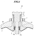
- FIG. 4 is a sectional view of a mouth ring portion of the pressure-resistant container according to the second embodiment of the present invention.
- the pressure-resistant container 20 of the embodiment is different from the pressure-resistant container 1 of the first embodiment in that the O-ring 10 constituting the first seal is excluded and that the first seal is composed only with the liquid sealant 11a.
- the liquid sealants 11b and 11c are not shown. However, they may be provided.
- the reliability of the sealing is improved by using the liquid sealant 11a in addition to the O-ring 10 as the first seal.
- the O-ring 10 When the O-ring 10 is applied, there is an advantage that an uniform sealing part can be obtained comparing to when only the liquid sealant 11a is used.
- the sealing may break due to the cycle fatigue by the deformation of the O-ring becoming great and by the great bending deformation occurring in the extending part 3c of the inner shell 3 which contacts with the O-ring 10.
- the pressure-resistant container 20 of the embodiment which only uses the liquid sealant 11a and which does not apply the O-rings 10 is effective.
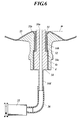
- FIG. 5 is a sectional view of a mouth ring portion of the pressure-resistant container according to the third embodiment of the present invention.
- the pressure-resistant container 30 of the embodiment is different from the pressure-resistant container 20 of the second embodiment in that the first seal is a liquid sealant 31 and that the liquid sealant 31 peripherally contacts with and covers the inner peripheral surface of the mouth ring 4 which is exposed between the inner shell 33 and the pressing member 5 and periphery of the opening of the inner shell 3 and does not contact with the pressing member 5.
- the liquid sealants 11b and 11c are provided to the pressing member 5 similarly as in the first embodiment, although they are not shown.
- the inner shell 33 covers along the mouth ring 4 to the circumference of the opening of the inner shell 33 in the embodiment.
- the extending part 3c is not provided as in the first and second embodiments, and the circumference of the opening of the inner shell 33 of the embodiment forms the cylindrical neck part 33b and covers the inner peripheral surface of the mouth ring 4.
- the liquid sealant 31 covers from the peak part 33e to the cylindrical neck part 33b of the inner shell 33 which covers the boundary of the inner tapered surface t1 and the outer tapered surface t2 (see FIG. 3 ) of the flange 4a, and further covers the inner peripheral surface of the mouth ring 4 which is exposed at more in outer side of the container than the cylindrical neck part 33b.
- the liquid sealant 31 is formed so as not to project more in the inner side of the container than the peak part 33e, and the liquid sealant 31 may not cover the peak part 33e itself.
- the mouth ring 4 is attached to the inner shell 33 similarly as in the first embodiment. Then, as shown in FIG. 6 , the inner shell 33 is fixed in the manner where the mouth ring 4 is placed in the lower side, and a stepped pipe 34 having a male screw part 34c to be screwed into the female screw at the outer side steps 4c of the mouth ring 4 at the outer periphery of the stepped pipe 34 is inserted into the mouth ring 4.
- the pipe 34 is screwed and entered into the mouth ring 4, and the pipe 34 is placed so that the front end 34a of the pipe 34 is placed at an upper position than the height position m of the peak part 33e.
- a part where it is not sealed by the liquid sealant 31 is previously sealed with a sealing tape 32 or the like so that the liquid sealant 31 does not enter therein.
- the liquid sealant is poured into the container through the pipe 34 with a syringe 35 or the like connected to the external end part 34d of the pipe 34 via a tube 36.
- the liquid sealant overflows from the pipe 34, and drops by the gravity to be filled between the mouth ring 4 and the end part 34b of the pipe 34 and between the inner shell 33 and the end part 34b of the pipe 34.
- the liquid sealant is poured by an amount in which the poured liquid sealant does not exceed a line m which is the amount specified by a preparatory experimental production in advance.
- the pipe 34 is pulled out.
- the mold release processing is carried out to the end part 34b of the pipe 34 before the insertion of the pipe 34 in order to prevent the adhesion of the end part 34b and the liquid sealant.
- the present invention can be used for a high pressure gas, such as compressed hydrogen, as a pressure-resistant container superior in its gas sealing property.
Landscapes
- Engineering & Computer Science (AREA)
- General Engineering & Computer Science (AREA)
- Mechanical Engineering (AREA)
- Filling Or Discharging Of Gas Storage Vessels (AREA)
- Pressure Vessels And Lids Thereof (AREA)
Abstract
Description
- The present invention relates to a pressure-resistant container in which an inner shell made of a resin is covered with an outer shell made of a fiber reinforced composite material.
- In recent years, so-called nonpolluting automobiles have been developed, and a part of them has been put to practical use with the aim of preventing an environmental deterioration caused by the exhaust gas of automobiles. For example, an automobile operating by means of a natural gas in which methane is the main component as the fuel has been authorized as a low pollution automobile, and about one million units of the automobiles have been actually used already all over the world.
Moreover, it is thought that a fuel cell powered automobile using hydrogen as its fuel will substitute for most of the current gasoline-driven automobiles in the future. There is a possibility that the natural gas and hydrogen that are used here are compressed natural gas and compressed hydrogen, respectively, and it is thought that the pressures will be ultrahigh pressures, such as 20 MPa to 25 MPa for the natural gas and 35 MPa to 70 MPa for hydrogen. Consequently, a tank (pressure-resistant container) having a pressure-resistant performance is needed, and a high pressure tank made of steel has been used conventionally. - When natural gas and hydrogen are used as the fuels of automobiles, it is preferred that the tanks to be mounted are light weighted from the point of view of the improvement of engine performance, the improvement of fuel consumption and the like. A tank made of an aluminum liner which is reinforced with carbon fibers has been used as an alternative for the steel tank. However, a tank using a resin liner in which the entire tank is made of resin has been developed in order to achieve further lightweight (for example, Patent Document 1).
- The tank made of resin liner is a gas tank composed of a resin inner shell (inner wall) having a gas barrier property and a fiber reinforced plastic (FRP) outer shell (outer wall) having a pressure resistance property wherein the outer shell covers the inner shell, and is lighter than a metal tank because the tank made of resin liner is mainly made of resin.
This sort of gas tank is provided with a nozzle attaching mouth ring in order to attach a nozzle for filling a gas into the tank and for taking the gas out from the tank. - The mouth ring portion is generally joined with the inner shell integrally. The mouth ring portion for screwing the nozzle or the like is generally made of a metal, and the inner shell is made of a material (the above mentioned resin, FRP or a light metal) different from that of the mouth ring portion from the point of view of the weight saving or the simplification of the manufacturing process.
Because the mouth ring portion and the inner shell which are made of different materials from each other are integrally joined, the sealing property of the joined part or the interface part of the inner shell and the mouth ring portion becomes important. - In particular, because the high pressure gas up to about 70 MPa is filled in the gas tank which is called the above mentioned high pressure natural gas tank or high pressure hydrogen gas tank for an automobile, an extremely high gas sealing property is required. The conventional gas tank yet has insufficient gas sealing property of the joined part or the interface part of the inner shell and the mouth ring portion.
- Patent Documents 2 to 5 propose pressure-resistant containers having improved gas sealing property of the mouth ring portion in the high pressure gas tanks made of resin.
- The pressure-resistant container described in Patent Document 2 has the structure of enhancing the gas sealing property of the mouth ring portion by adopting the structure of receiving a disk-like flange part of the mouth ring portion with upper and lower lips at the end part of the inner shell.
However, in the pressure-resistant container described in Patent Document 2, the end part of the mouth ring is exposed to its internal gas, and the internal pressure of the gas is directly applied to the end part of the mouth ring portion. Consequently, even when gas leakage does not occur just after the manufacturing of the pressure-resistant container, creeping occurs in the resin of the inner shell to shrink and a gap is generated at an interface of the inner shell and the mouth ring while using the container for a long time. Thus, there is a possibility that gas leakage might occur from the gap at the interface. - Moreover, in the pressure-resistant container described in
Patent Document 3, locking grooves are provided at the upper and lower surfaces of a disk-like flange part of the mouth ring, and a tab which fits with the upper and lower locking groove is formed at the end part of the inner shell to join the upper and lower locking grooves.
Thereby, the pressure-resistant container is structured so as to oppose the force which tears off both the lips with the locking groove, which force is a shearing force operates on both the lip parts joined to the locking groove at the upper and lower surfaces of the disk-like flange when the inner shell swells at the time of the swelling of the container by an internal pressure when a high pressure gas is kept in the pressure-resistant container.
However, in the pressure-resistant container described inPatent Document 3, the end part of the mouth ring is also exposed to the internal gas, and the internal pressure of the gas is applied directly to the end part of the mouth ring. Consequently, there is possibility that gas leakage might occur by the same reason as described above. - Furthermore, the pressure-resistant container described in
Patent Document 4 aims to enhance the gas sealing property by adopting the following structure: the mouth ring intervenes at the inner side of the opening part of the inner shell manufactured by the blow molding; a sealing ring made of rubber or the like is fitted to the shoulder part of the inner shell; the sealing ring is pressed by a pressing member made of a metal or the like; and filament winding molding is performed thereover.
Even when the pressing member of the sealing ring is made of a metal, the fitting part of the sealing ring is only structured with the resin-made inner shell. Therefore, even when a gas leakage does not occur right after the manufacturing of the pressure-resistant container, the plastic of the inner shell creeps and the inner shell shrinks while the container is being used for a long time.
Thus, there is a possibility that gas leakage might occur in the pressure-resistant container similarly as the pressure-resistant containers described inPatent Documents 2 and 3. Even when it is tempted to increase the number of sealing ring in response to the shrinking of the inner shell, the product container is needed to be disassembled, and further in the case of exchanging a deteriorated sealing, the product container is also needed to be disassembled, and it is not only troublesome but also uneconomical. - As a pressure-resistant container to solve the problem which is common to the above pressure-resistant containers described in Patent Documents 2 to 4, there is the pressure-resistant container described in
Patent Document 5.
In the container described inPatent Document 5, a cylindrical neck part, a tabular extending part extending outward and a bent part bent to the inner shell side are successively connected to the pole portion of the inner shell, and the cross section of the end part of the inner shell is bended to the inner shell side to be embedded in the mouth ring and an O-ring is jointly used between the pressing part and the extending part. Thereby, the end part of the mouth ring is prevented from being exposed to the internal gas and the internal pressure of the gas is prevented from being applied directly to the end part of the mouth ring.
However, in this method, although one side is the pressing member made of metal which can secure the surface accuracy relatively easily, the other side is made of plastic which cannot secure the surface accuracy. Consequently, this structure lacks the reliability of scaling. Moreover, it is needed to use rotational molding which takes long time for the molding of the plastic liner of the inner shell in order to bend the cross section of the end part of the inner shell to the inner shell side to be embedded into the mouth ring, and the lowering of the cost of the inner shell is prevented.
Moreover, in order to support the bent part of the inner shell with the end part of the mouth ring in the inner side of the tank, the end part is formed so as to project toward the inner side. The projecting part causes no problem in the case of a relatively low pressure tank. However, the bending strength of the mouth ring at the projecting part by the internal pressure of the tank becomes severe in an ultra high pressure tank, such as 70 MPa, and there is a possibility that the breaking of the mouth ring occurs in a repetition cycle. - Patent Document 1:
- Japanese Patent Publication No.
Hei 5-88665 - Patent Document 2:
- Japanese Patent Application Laid-Open Publication No.
Hei 6-42698 - Patent Document 3:
- Japanese Patent Application Laid-Open Publication No.
Hei 6-137433 - Patent Document 4:
- Japanese Patent Application Laid-Open Publication No.
Hei 8-219387 - Patent Document 5:
- Japanese Patent Application Laid-Open Publication No.
Hei 10-332085 - However, the pressure-resistant container described in
Patent Document 5 also has the following problem. That is, even when one side is the pressing member made of metal which can easily secure its surface accuracy, the other side is made of plastic which cannot secure its surface accuracy. Consequently, this structure lacks the reliability of sealing.
Moreover, in order to embed the edge part of the inner shell into the mouth ring in a shape of being bent outside, the mouth ring is needed to be set in a centrifugal mold and the rotational molding which takes a long time is needed to be used for the molding of the plastic liner of the inner shell, and thereby the lowering of the cost of the inner shell is prevented.
Moreover, in order to support the bent part of the inner shell with the end part of the mouth ring at the inner side of the tank, the end part of the mouth ring is formed so as to project to the inner side. The projecting part causes no problem in the case of a relatively low pressure tank. However, the bending strength of the mouth ring at the projecting part by the internal pressure of the tank becomes greater in an ultra high pressure tank, such as 70 MPa, and there is a possibility that the breaking of the mouth ring occurs in a repetition cycle. - The present invention was completed as the result of a keen examination in order to provide a pressure-resistant container which solves the above several problems at once, and the object of the present invention is to make the manufacturing of the pressure-resistant container in which the inner shell is covered with the outer shell easy and to enhance the gas sealing property at the edge part (interface part) of the covering where the inner shell and the mouth ring adhere to one another.
- The invention of claim 1 for solving the above problem is a pressure-resistant container comprising an inner shell, an outer shell to cover the inner shell, a cylindrical mouth ring to penetrate the outer shell to be connected to an opening formed at the inner shell, a peripheral part of the opening at the inner shell covering an end surface of the mouth ring at an inner side of the container, a cylindrical pressing member screwed into an inner peripheral surface of the mouth ring, a first seal peripherally contacting with the inner peripheral surface of the mouth ring which is exposed between the inner shell and the pressing member and with a periphery of the opening of the inner shell in an integral manner, a valve having a screw part screwed into the inner peripheral surface of the mouth ring at an outer side of the container than the pressing member and having an inner end part inserted into a hole part of the pressing member and a second seal for sealing between an outer peripheral surface of the inner end part and an inner peripheral surface of the pressing member.
Here, "peripherally contacting" means contacting with the other material so as to go around the material (the same applies hereinafter). - The invention according to claim 2 is the pressure-resistant container as claimed in claim 1, wherein the first seal peripherally contacts with the inner peripheral surface of the mouth ring which is exposed between the inner shell and the pressing member, the periphery of the opening of the inner shell and the pressing member in the integral manner.
- The invention according to
claim 3 is the pressure-resistant container as claimed in claim 1 or 2, wherein the peripheral part covers a predetermined range of the inner peripheral surface of the mouth ring by peripherally contacting with the predetermined range continuously to the end surface of the mouth ring at the inner side of the container. - The invention according to
claim 4 is the pressure-resistant container as claimed inclaim 3, wherein the peripheral part comprises an extending part which extends from a covering part of the predetermined range toward an inner part of the mouth ring, and the first seal peripherally contacts with the extending part. - The invention according to
claim 5 is the pressure-resistant container as claimed in any one of claims 1 to 4, wherein a flange which is sandwiched between the outer shell and the inner shell is formed at an end part of the mouth ring at the inner side of the container. - The invention according to
claim 6 is the pressure-resistant container as claimed inclaim 5, wherein the second seal is disposed at an inner side of the container than a joining position of the flange and a cylindrical neck part of the mouth ring. - The invention according to
claim 7 is the pressure-resistant container as claimed in any one of claims 1 to 6, wherein the first seal is a liquid sealant. - The invention according to claim 8 is the pressure-resistant container as claimed in any one of claims 1 to 6, wherein the first seal is an O-ring and a liquid sealant adhering to the O-ring.
- The invention according to claim 9 is the pressure-resistant container as claimed in any one of claims 1 to 8, wherein a liquid sealant is attached between an outer peripheral surface of the pressing member and the inner peripheral surface of the mouth ring opposed to the outer peripheral surface of the pressing member.
- The invention according to
claim 10 is the pressure-resistant container as claimed in any one of claims 1 to 9, wherein a liquid sealant is attached between an end surface of the pressing member at an outer side of the container and the inner peripheral surface of the mouth ring. - The invention according to claim 11 is the pressure-resistant container as claimed in any one of claims 1 to 10, wherein the second seal is an O-ring.
- The invention according to
claim 12 is the pressure-resistant container as claimed in claim 11, wherein a circumferential groove to hold the O-ring of the second seal is formed at an outer peripheral surface of the inner end part. - The invention according to
claim 13 is the pressure-resistant container as claimed in any one of claims 1 to 12, wherein a flange part is provided at an end part of the valve at an outer side of the container, and a third seal is provided to seal a part between the flange part and an end surface of the mouth ring at the outer side of the container. - The invention according to
claim 14 is the pressure-resistant container as claimed inclaim 13, wherein the third seal is an O-ring. - The invention according to claim 15 is the pressure-resistant container as claimed in any one of claims 1 to 14, wherein the inner shell is made of a resin, and the outer shell is made of a composite material of a fiber reinforced resin.
- According to the invention described in claim 1, the first seal peripherally contacts with the inner peripheral surface of the mouth ring which is exposed between the inner shell and the pressing member and a periphery of the opening of the inner shell in an integral manner. Consequently, the gas sealing property of the edge part of the covering where the inner shell and the mouth ring adhere to one another can be enhanced, and thereby an effect of realizing the high pressure resistance property of the container is obtained.
According to the invention described in claim 2, the first seal peripherally contacts with the inner peripheral surface of the mouth ring which is exposed between the inner shell and the pressing member, the periphery of the opening of the inner shell and the pressing member in an integral manner. Consequently, the edge part of the covering where the inner shell and the mouth ring adhere to one another can be sealed.
Furthermore, because the second seal seals the part between the outer peripheral surface of the inner end part of the valve and the inner peripheral surface of the pressing member, the internal gas will not go around the end part of the pressing member at the outer side of the container to enter the edge part of the covering where the inner shell and the mouth ring adhere to one another, and consequently the gas sealing property of the edge part of the covering where the inner shell and the mouth ring adhere to one another can be enhanced. Thus, the effect of realizing the high pressure resistance property of the container is obtained.
Moreover, because it is sufficient for the inner shell to cover at least the end surface of the mouth ring at the inner side of the container, a molding technique having good productivity, such as the blow molding, can be applied to the inner shell before attaching the mouth ring thereto, and the mouth ring that has been configured separately can be attached to the inner shell by adhesion, welding or the like, after the molding of the inner shell. Consequently, the effect of making the manufacturing of the pressure-resistant container easy to reduce the cost is obtained. -
- FIG. 1
- is an outline view of the entire pressure-resistant container according to the First and the Second Embodiments of the present invention.
- FIG. 2
- is a sectional view of the mouth ring portion of the pressure-resistant container according to the First Embodiment of the present invention.
- FIG. 3
- is a partially enlarged view of
FIG. 2 . - FIG. 4
- is a sectional view of the mouth ring portion of the pressure-resistant container according to the Second Embodiment of the present invention.
- FIG. 5
- is a sectional view of the mouth ring portion of the pressure-resistant container according to the Third Embodiment of the present invention.
- FIG. 6
- is a view for explaining the forming method of the liquid sealant in the Third Embodiment of the present invention.
- Hereinafter, embodiments of the present invention will be described with reference to the drawings. The following are the embodiments of the present invention and they do not limit the present invention.
- At first, the first embodiment of the present invention will be described with reference to
FIGS. 1 to 3 .
FIG. 1 is an outline view of the entire pressure-resistant container according to the first embodiment of the present invention.
As shown inFIG. 1 , the pressure-resistant container 1 of the present embodiment comprises an outer shell 2 and mouth rings 4. The outer shell 2 is made of a composite material of a fiber reinforced resin such as CFRP, and is composed of acylinder part 2a anddome parts cylinder part 2a. The outer shell 2 covers an inner shell (omitted from the drawing). The mouth rings 4 are provided at the peak parts of thedome parts -
FIG. 2 is a sectional view of a mouth ring portion of the pressure-resistant container 1.FIG. 3 is a partially enlarged view ofFIG. 2 . As shown inFIG. 2 or3 , anopening 3d connected to the mouth rings 4 is formed at theinner shell 3. Theinner shell 3 is made of a resin and has a gas barrier property. That is, theinner shell 3 is a member to bear the function of a gas barrier in the pressure-resistant container 1. However, because theinner shell 3 is made of the resin and it is thin and easy to swell, the pressure resistance of the container is enhanced by the outer shell 2 made of the composite material of the fiber reinforced resin covering theinner shell 3. That is, the outer shell 2 is the member to bear the function of pressure resistance in the pressure-resistant container 1. - The
mouth ring 4 is cylindrical. Aflange 4a is formed at the end part of themouth ring 4 at the inner side of the container. Theperipheral part 3a of theopening 3d of theinner shell 3 covers the end surface of themouth ring 4 at the inner side of the container (that is, the end surface of theflange 4a at the inner side of the container) by adhesion, welding or the like.
The circumference of theflange 4a is formed to be sharp, and an inner tapered surface t1 and an outer tapered surface t2 are formed on the end surface of theflange 4a at the inner side of the container.
The inner shell 3 (peripheral part 3a) covers the inner tapered surface t1 and the outer tapered surface t2 continuously to both of the inner tapered surface t1 and the outer tapered surface t2. - A
cylindrical neck part 3b is formed at a part nearer to theopening 3d than the part of theperipheral part 3a that covers the inner tapered surface t1, and further, an extendingpart 3c is formed at a part even more nearer to theopening 3d (theperipheral part 3a includes thecylindrical neck part 3d and the extendingpart 3 c).
Thecylindrical neck part 3b covers a predetermined range n of the inner peripheral surface of themouth ring 4 by thecylindrical neck part 3b peripherally contacting with the predetermined range. That is, theperipheral part 3a covers a predetermined range n of the inner peripheral surface of themouth ring 4 continuously to the end surface (the inner tapered surface t1 and the outer tapered surface t2) of themouth ring 4 at the inner side of the container by theperipheral part 3a peripherally contacting with the predetermined range n.
The extendingpart 3c is bent at the covered edge part P to extend from the covering part of the predetermined range n to the inner part of themouth ring 4. - The inner peripheral surface of the
mouth ring 4 has a stepped structure in which the diameter in the outer side of the container is larger. A female screw into which thepressing member 5 is screwed is formed at theinner side steps 4b. A female screw into which thescrew part 6b of thevalve 6 is screwed is formed at the outer side steps 4c. - The
pressing member 5 is formed in a simple cylindrical shape and does not have a flange nor a taper. A male screw screwed into theinner side steps 4b of themouth ring 4 is formed at the outer peripheral surface of thepressing member 5.
Thevalve 6 has aflange part 6a, thescrew part 6b and aninner end part 6c in which the diameters become smaller stepwise toward the inner part of the container in order. A male screw screwed into the outer side steps 4c of themouth ring 4 is formed at the outer peripheral surface of thescrew part 6b. Acircumferential groove 6d to hold an O-ring 12 (second seal) is formed on the outer peripheral surface of theinner end part 6c. A gas airway is formed at thevalve 6, although it is not shown. - The pressure-resistant container 1 is manufactured by molding and curing the outer shell 2 by the filament winding method so that the outer shell 2 covers the outside of the
inner shell 3 and theflanges 4a of the mouth rings 4, and so that the outer shell 2 makes the end part of themouth ring 4 at the outer side of the container to project. The pressure-resistant container 1 thus has the structure in which themouth ring 4 protrudes the outer shell 2 (dome part 2b). Amale screw 4d screwed into a tighteningnut 7 is formed at the outer peripheral surface of the end part of themouth ring 4 projecting to the outer side of the outer shell 2 (dome part 2b).
Theflange 4a is put between the outer shell 2 (dome part 2b) and theinner shell 3. There is nothing between theflange 4a and the outer shell 2 (dome part 2b), and theflange 4a and the outer shell 2 (dome part 2b) contact with each other. - The pressure-resident container 1 has the above described structure of each portion, and the
pressing member 5 is screwed into theinner side steps 4b of themouth ring 4, thescrew part 6b of thevalve 6 is screwed into the outer side steps 4c of themouth ring 4, and theinner end part 6c is inserted into the hole part of thepressing member 5 as shown inFIGS. 2 and3 .
The O-ring 12 (second seal) held in thecircumferential groove 6d is also disposed in the hole part of thepressing member 5 along with theinner end part 6c being inserted into the hole part of thepressing member 5. The O-ring 12 (second seal) seals between the outer peripheral surface of theinner end part 6c and the inner peripheral surface of thepressing member 5. The O-ring 12 (second seal) is disposed at a position more in the inner side of the container than a joining position C of theflange 4a and acylindrical neck part 4e of themouth ring 4. - Moreover, the
flange part 6a presses the O-ring 13 (third seal) onto the end surface of themouth ring 4 at the outer side of the container. Thereby, the space between theflange part 6a and the end surface of themouth ring 4 at the outer side of the container is sealed. - The first seal is composed of an O-
ring 10 and aliquid sealant 11a. Theliquid sealant 11 a adheres to the O-ring 10 to cover the O-ring 10.
The first seal peripherally contacts with an inner peripheral surface b of themouth ring 4 which is exposed between theinner shell 3 and thepressing member 5. Moreover, the first seal peripherally contacts with the surface of the extendingpart 3c of theinner shell 3 at the outer side of the container. Furthermore, the first seal peripherally contacts with the surface (O-ring pressing surface) of thepressing member 5 at the inner side of the container.
The surface of the extendingpart 3c of theinner shell 3 at the outer side of the container and the surface of thepressing member 5 at the inner side of the container are opposed to each other, and the inner peripheral surface b of themouth ring 4 is exposed between the above surface of the extendingpart 3c of theinner shell 3 at the outer side of the container and the surface of thepressing member 5 at the inner side of the container.
The first seals peripherally contacts with the surface (the surface of the extendingpart 3c at the outer side of the container in the embodiment) of theinner shell 3 adjacent to the inner peripheral surface b.
The first seal peripherally contacts with the surface of thepressing member 5 adjacent to the inner peripheral surface b at the inner side of the container.
In such manner, the first seal peripherally contacts with each part of the inner peripheral surface b of themouth ring 4 exposed between theinner shell 3 and thepressing member 5, the periphery of theopening 3d of theinner shell 3 adjacent to the inner peripheral surface b and thepressing member 5 in an integral manner.
Theliquid sealant 11a of the first seal always peripherally contacts with the above mentioned three surfaces.
The O-ring 10 of the first seal peripherally contacts with the above mentioned three surfaces at least when a predetermined pressure or more is loaded thereon. - In addition to the first to third seals, a
liquid sealant 11b is attached between the outer peripheral surface of thepressing member 5 and the inner peripheral surface (theinner side steps 4b) of themouth ring 4 opposed to the outer peripheral surface of thepressing member 5 in order to perform a greater sealing.
With the same object, aliquid sealant 11c is attached between the surface of thepressing member 5 at the outer side of the container and the inner peripheral surface (theinner side step 4b) of themouth ring 4. - Next, the sealing property and the high pressure resistance of the pressure-resistant container 1 will be further described.
Themouth ring 4 and theinner shell 3 are joined to each other by adhesion or welding. The area of theflange 4a of themouth ring 4 has an aspect of being determined by the factor of the strength thereof. However, the area is determined mainly for securing the joining area of theinner shell 3 and themouth ring 4 wherein the joining area is needed as a seal. Consequently, sufficient sealing can be carried out by the adhesion or the welding. Moreover, because the resininner shell 3 has sufficient flexibility comparing to the composite material, such as CFRP, of the outer shell 2, theinner shell 3 is pressed to themouth ring 4 by the internal pressure of the tank, and thereby, the sealing property is improved. - As shown in
FIG. 3 , a high pressure gas G is filled in the inner side of the first and second seals. It is important not to expose the covered edge parts P of theinner shell 3 and themouth ring 4 to the internal gas in order to keep the sealing property in a good condition. When the covered edge part P is exposed to the internal gas, then the interfacial peeling or the like of theinner shell 3 and themouth ring 4 from the covered edge part P occurs by the pressure of the internal gas, and there is a possibility that a gas leakage occurs. - In the pressure-resistant container 1, the O-
ring 10 which is loaded with a pressure by the high pressure gas G deforms so as to enlarge its diameter, and the O-ring 10 contacts with the inner peripheral surface b of themouth ring 4 by a pressure. Moreover, the O-ring 10 loaded with the pressure by the high pressure gas G deforms in its cross section, and the O-ring 10 contact with the surface of thepressing member 5 at the inner side of the container and the extendingpart 3c of theinner shell 3 to adhere closely to both of them in larger area. In this way, the sealing property of the container is enhanced by the O-ring 10 when a high presser is load. - The
valve 6 is secured by the screwing of thescrew part 6b of thevalve 6 into the female screw of themouth ring 4 at the outer side steps 4c. The O-ring 12 is held in the circumferential groove at theinner end part 6c, and sealing is carried out between theinner end part 6c and the surface of thepressing member 5 at the inner side. Because the pressing member 5 (ring) can be manufactured with high accuracy by a machining process, the surface accuracy necessary for sealing can be easily secured.
Furthermore, in the pressure-resistant container, the O-ring 12 which is loaded with a pressure by the high pressure gas G causes a deformation in its cross section, and the O-ring 12 contacts with the inner peripheral surface of thepressing member 5 and the bottom of thecircumference groove 6d with pressure to adhere closely to both of them. In this way, the sealing property is enhanced by the O-ring 12 when a high pressure is loaded. - Generally, the surface accuracy of the surface to which an O-ring is applied is strictly regulated in order to secure the sealing performance, and a sufficient sealing can be obtained only by the O-ring. However, because the resin
inner shell 3 cannot secure the surface accuracy at the sealing part, theliquid sealant 11a is used together in the first seal, and thereby the reliability of the sealing is improved. - As described above, the covered edge part P and the periphery are blocked from the high pressure gas G by the first seal composed of the O-
ring 10 and theliquid sealant 11a, and the occurrence of a large stress to the covered edge part P is prevented. Consequently, the occurrence of gas leakage due to the occurrence of the interfacial peeling and the like of theinner shell 3 and themouth ring 4 from the covered edge part P is prevented. - Furthermore, the O-ring 12 (second seal) seals the space between the outer peripheral surface of the
inner end part 6c of thevalve 6 and the inner peripheral surface of thepressing member 5, and consequently the high pressure gas G is prevented from entering the outside space S of the O-ring 12. Consequently, the high pressure gas G will not enter the covered edge part P of theinner shell 3 and themouth ring 4 from out side of thepressing member 5 by going around the end part of thepressing member 5 at the outer side of the container, and the gas sealing property of the covered edge part P of theinner shell 3 and the mouth rings 4 can be enhanced.
When the high pressure gas G leaks to the outside space S of the O-ring 12, there is a possibility that not only the pressure at the outer side of the O-ring 12 increases but also the pressure at the outer side of the O-ring 10 increases. When the pressure at outer side of both of the O-rings rings
Accordingly, the pressure-resistant container 1 is provided not only with the first seal (O-ring 10 andliquid sealant 11a) but also with the second seal (O-ring 12) together, and thereby the gas sealing property is enhanced. Thus the high pressure resistance of the container is realized. - The
liquid sealants pressing member 5. - By the
inner shell 3 covering not only the end surfaces (tapered surfaces t1 and t2) of themouth ring 4 at the outer side of the container but also the predetermined range n of the inner peripheral surface, the joining strength between theinner shell 3 and themouth ring 4 increases, and then the gas sealing property and the pressure resistance are enhanced. - By forming the extending
part 3c in theinner shell 3, even when the thininner shell 3 is used, the seat for the O-ring 10 can be secured, and the thickness from the surface of theliquid sealant 11 a to the covered edge part P can be secured so as to be thick. Consequently, the gas sealing property can be enhanced. - The
flange 4a is also for latching themouth ring 4 to the outer shell 2 for preventing themouth ring 4 from springing outside when themouth ring 4 receives an internal pressure in addition for securing the covered area of theinner shell 3 and themouth ring 4 so as to be large.
The tighteningnut 7 is for latching themouth ring 4 to the outer shell 2 so that themouth ring 4 does not fall in the inner part of the container when themouth ring 4 receives a load in the inner direction of the container.
That is, themouth ring 4 is fixed to the outer shell 2 with theflange 4a and the tighteningnut 7. - The joining part of the
cylindrical neck part 4e and theflange 4a of themouth ring 4 is not only under a severe condition in the aspect of the strength by the bending load caused by the deformation of the tank at the time of pressure loading and the load caused by the internal pressure of the tank acting thereto, but also the joining part causes a great deformation of themouth ring 4. In this case, a large gap is generated between thepressing member 5 and themouth ring 4 to reduce the sealing performance. Moreover, because a similar situation occurs between thevalve 6 and thepressing member 5, it is especially important for the sealing performance that the deformation at the joining part of themouth ring 4 is small. In the pressure-resistant container 1, because the O-ring 12 (second seal) is disposed at a position more in the inner side of the container than the joining position C of theflange 4a and thecylindrical neck part 4e of themouth ring 4, the internal pressure of the tank does not operate directly to the joining part of thecylindrical neck part 4e and theflange 4a of themouth ring 4. Thereby, at least the deformation due to the internal pressure of the tank does not occur, and the sealing performance can be enhanced. - For the second seal, a back-up ring 14 (shown in
FIG. 3 by a broken line) to the O-ring 12 can be applied according to the size of the gap to be sealed to improve the sealing property.
As described above, a high gas sealing property and a high pressure resistance can be realized. - Next, a manufacturing method of the pressure-resistant container 1 will be described.
The inner shell (liner) 3 is manufactured by a blow molding in advance, and themouth ring 4 made of a metal which has theflange 4a is separately manufactured. Themouth ring 4 is attached to theinner shell 3 by the adhesion or welding of theinner shell 3 and theflange 4a. In the case of the adhesion, an adhesive is applied to predetermined ranges of both of themouth ring 4 and theinner shell 3, and the adhesion is carried out while pressurizing themouth ring 4 and theinner shell 3. The pressurization is continued to be loaded until the curing of the adhesive with a specialized jig.
Next, a liquid sealant is applied (the application of theliquid sealants part 3c of theinner shell 3, the flat surface part that is the end surface of thepressing member 5 at the inner side of the container, the male screw part at the outer periphery of thepressing member 5 and the inner peripheral surface (female screw part) of themouth ring 4 opposed to the male screw part, and the O-ring 10 is placed on the extendingpart 3c.
Next, the pressingmember 5 is screwed and entered into the female screw of theinner side steps 4b of themouth ring 4, and the O-ring 10 is squashed to a predetermined squashing amount. Next, the end part of thepressing member 5 at the outer side of the container is further sealed by a liquid seal (the placement of theliquid sealant 11c).
Next, thevalve 6 in which the O-ring 12 is fitted in thecircumferential groove 6d is screwed into the female screw at the outer side steps 4c of themouth ring 4 to be tightened into the predetermined positions. At this time, the O-ring 13 placed at the upper end of themouth ring 4 in advance is pressed with theflange part 6a of thevalve 6 to carry out the third seal. A back-up ring may be applied to the O-ring 13, although the back-up ring is not shown.
Next, the outer shell 2 to cover theinner shell 3 and theflange 4a is molded by the filament winding method. Before the curing of the resin constituting the outer shell 2, the tighteningnut 7 is screwed into themale screw 4d of themouth ring 4, and the outer shell 2 is tightened with theflange 4a and the stuffingnut 7. After that, the resin is cured. Adhesives (in paste form) may be applied to the surface of thenut 7 contacting with the outer shell 2 as needed.
By the above process, the pressure-resistant container 1 is completed. - As described above, the blow molding technique which has good productivity can be applied to the manufacturing of the
inner shell 3, and the mouth ring configured separately can be attached to the inner shell by adhesion, welding and the like. Consequently, the pressure-resistant container can be simply manufactured and the cost of the manufacturing can be reduced. - Here, by removing the
valve 6 from themouth ring 4, the maintenance and replacement of the O-rings valve 6 from themouth ring 4, the condition of the O-ring 10, the pressingmember 5, theliquid sealants part 3c can be confirmed. The O-ring 10, the pressingmember 5, and theliquid sealants - Next, a second embodiment of the present invention will be described with reference to
FIG. 4. FIG. 4 is a sectional view of a mouth ring portion of the pressure-resistant container according to the second embodiment of the present invention. The pressure-resistant container 20 of the embodiment is different from the pressure-resistant container 1 of the first embodiment in that the O-ring 10 constituting the first seal is excluded and that the first seal is composed only with theliquid sealant 11a. Theliquid sealants - As described above, in the case of the pressure-resistant container 1 of the first embodiment, the reliability of the sealing is improved by using the
liquid sealant 11a in addition to the O-ring 10 as the first seal.
When the O-ring 10 is applied, there is an advantage that an uniform sealing part can be obtained comparing to when only theliquid sealant 11a is used. However, in the case where an ultrahigh pressure is caused, the sealing may break due to the cycle fatigue by the deformation of the O-ring becoming great and by the great bending deformation occurring in the extendingpart 3c of theinner shell 3 which contacts with the O-ring 10. In such case, the pressure-resistant container 20 of the embodiment which only uses theliquid sealant 11a and which does not apply the O-rings 10 is effective. - Next, a third embodiment of the present invention will be described with reference to
FIG. 5. FIG. 5 is a sectional view of a mouth ring portion of the pressure-resistant container according to the third embodiment of the present invention. The pressure-resistant container 30 of the embodiment is different from the pressure-resistant container 20 of the second embodiment in that the first seal is aliquid sealant 31 and that theliquid sealant 31 peripherally contacts with and covers the inner peripheral surface of themouth ring 4 which is exposed between theinner shell 33 and thepressing member 5 and periphery of the opening of theinner shell 3 and does not contact with thepressing member 5. It is preferable that theliquid sealants pressing member 5 similarly as in the first embodiment, although they are not shown. - As shown in
FIG. 5 , theinner shell 33 covers along themouth ring 4 to the circumference of the opening of theinner shell 33 in the embodiment. In the embodiment, the extendingpart 3c is not provided as in the first and second embodiments, and the circumference of the opening of theinner shell 33 of the embodiment forms thecylindrical neck part 33b and covers the inner peripheral surface of themouth ring 4.
Theliquid sealant 31 covers from thepeak part 33e to thecylindrical neck part 33b of theinner shell 33 which covers the boundary of the inner tapered surface t1 and the outer tapered surface t2 (seeFIG. 3 ) of theflange 4a, and further covers the inner peripheral surface of themouth ring 4 which is exposed at more in outer side of the container than thecylindrical neck part 33b. Theliquid sealant 31 is formed so as not to project more in the inner side of the container than thepeak part 33e, and theliquid sealant 31 may not cover thepeak part 33e itself. - Hereinafter, the forming method of the
liquid sealant 31 will be described with reference toFIG. 6 .
First, themouth ring 4 is attached to theinner shell 33 similarly as in the first embodiment.
Then, as shown inFIG. 6 , theinner shell 33 is fixed in the manner where themouth ring 4 is placed in the lower side, and a steppedpipe 34 having amale screw part 34c to be screwed into the female screw at the outer side steps 4c of themouth ring 4 at the outer periphery of the steppedpipe 34 is inserted into themouth ring 4. Thepipe 34 is screwed and entered into themouth ring 4, and thepipe 34 is placed so that thefront end 34a of thepipe 34 is placed at an upper position than the height position m of thepeak part 33e.
A part where it is not sealed by theliquid sealant 31 is previously sealed with a sealingtape 32 or the like so that theliquid sealant 31 does not enter therein.
The liquid sealant is poured into the container through thepipe 34 with asyringe 35 or the like connected to theexternal end part 34d of thepipe 34 via atube 36. The liquid sealant overflows from thepipe 34, and drops by the gravity to be filled between themouth ring 4 and theend part 34b of thepipe 34 and between theinner shell 33 and theend part 34b of thepipe 34.
The liquid sealant is poured by an amount in which the poured liquid sealant does not exceed a line m which is the amount specified by a preparatory experimental production in advance. After the curing of theliquid sealant 31, thepipe 34 is pulled out. The mold release processing is carried out to theend part 34b of thepipe 34 before the insertion of thepipe 34 in order to prevent the adhesion of theend part 34b and the liquid sealant. - Here, the whole disclosure of Japanese Patent Application
2006-91106 filed on March 29, 2006 - The present invention can be used for a high pressure gas, such as compressed hydrogen, as a pressure-resistant container superior in its gas sealing property. Description of Reference Signs
-
- C
- = joining position
- P =
- P = covered edge part
- G =
- G = high pressure gas
- 1 =
- pressure-resistant container (first embodiment)
- 2 =
- outer shell
- 3 =
- inner shell
- 3a =
- peripheral part
- 3b =
- cylindrical neck part
- 3c =
- extending part
- 3d =
- opening
- 4 =
- mounth ring
- 4a =
- flange
- 4e =
- cylindrical neck part
- 5 =
- pressing member
- 6 =
- valve
- 6a
- flange part
- 6c =
- inner end part
- 6d =
- circumferential groove
- 6b =
- outer side step
- 6b
- screw part
- 7
- tightening nut
- 10 =
- O-ring (first seal)
- 11a =
- liquid sealant (first seal)
- 11b, 11c =
- liquid sealant
- 12 =
- O-ring (second seal)
- 13 =
- O-ring (third seal)
- 20 =
- pressure-resistant container (second embodiment)
- n =
- predetermined range of inner peripheral surface of mouth ring
Claims (15)
- A pressure-resistant container, comprising:- an inner shell;- an outer shell to cover the inner shell;- a cylindrical mouth ring to penetrate the outer shell to be connected to an opening formed at the inner shell, a peripheral part of the opening at the inner shell covering an end surface of the mouth ring at an inner side of the container;- a cylindrical pressing member screwed into an inner peripheral surface of the mouth ring;- a first seal peripherally contacting with the inner peripheral surface of the mouth ring which is exposed between the inner shell and the pressing member and with a periphery of the opening of the inner shell in an integral manner;- a valve having a screw part screwed into the inner peripheral surface of the mouth ring at an outer side of the container than the pressing member and having an inner end part inserted into a hole part of the pressing member; and- a second seal for sealing between an outer peripheral surface of the inner end part and an inner peripheral surface of the pressing member.
- The pressure-resistant container as claimed in claim 1,
wherein the first seal peripherally contacts with the inner peripheral surface of the mouth ring which is exposed between the inner shell and the pressing member, the periphery of the opening of the inner shell and the pressing member in the integral manner. - The pressure-resistant container as claimed in claim 1 or 2,
wherein the peripheral part covers a predetermined range of the inner peripheral surface of the mouth ring by peripherally contacting with the predetermined range continuously to the end surface of the mouth ring at the inner side of the container. - The pressure-resistant container as claimed in claim 3,
wherein the peripheral part comprises an extending part which extends from a covering part of the predetermined range toward an inner part of the mouth ring, and the first seal peripherally contacts with the extending part. - The pressure-resistant container as claimed in any one of claims 1 to 4,
wherein a flange which is sandwiched between the outer shell and the inner shell is formed at an end part of the mouth ring at the inner side of the container. - The pressure-resistant container as claimed in claim 5,
wherein the second seal is disposed at an inner side of the container than a joining position of the flange and a cylindrical neck part of the mouth ring. - The pressure-resistant container as claimed in any one of claims 1 to 6,
wherein the first seal is a liquid sealant. - The pressure-resistant container as claimed in any one of claims 1 to 6,
wherein the first seal is an O-ring and a liquid sealant adhering to the O-ring. - The pressure-resistant container as claimed in any one of claims 1 to 8,
wherein a liquid sealant is attached between an outer peripheral surface of the pressing member and the inner peripheral surface of the mouth ring opposed to the outer peripheral surface of the pressing member. - The pressure-resistant container as claimed in any one of claims 1 to 9,
wherein a liquid sealant is attached between an end surface of the pressing member at an outer side of the container and the inner peripheral surface of the mouth ring. - The pressure-resistant container as claimed in any one of claims 1 to 10,
wherein the second seal is an O-ring. - The pressure-resistant container as claimed in claim 11,
wherein a circumferential groove to hold the O-ring of the second seal is formed at an outer peripheral surface of the inner end part. - The pressure-resistant container as claimed in any one of claims 1 to 12,
wherein a flange part is provided at an end part of the valve at an outer side of the container, and a third seal is provided to seal a part between the flange part and an end surface of the mouth ring at the outer side of the container. - The pressure-resistant container as claimed in claim 13,
wherein the third seal is an O-ring. - The pressure-resistant container as claimed in any one of claims 1 to 14,
wherein the inner shell is made of a resin, and the outer shell is made of a composite material of a fiber reinforced resin.
Applications Claiming Priority (2)
| Application Number | Priority Date | Filing Date | Title |
|---|---|---|---|
| JP2006091106A JP4875915B2 (en) | 2006-03-29 | 2006-03-29 | Pressure vessel |
| PCT/JP2007/055632 WO2007119444A1 (en) | 2006-03-29 | 2007-03-20 | Pressure-resistant vessel |
Publications (4)
| Publication Number | Publication Date |
|---|---|
| EP2000734A2 true EP2000734A2 (en) | 2008-12-10 |
| EP2000734A9 EP2000734A9 (en) | 2009-03-25 |
| EP2000734A4 EP2000734A4 (en) | 2011-07-06 |
| EP2000734B1 EP2000734B1 (en) | 2018-05-02 |
Family
ID=38609232
Family Applications (1)
| Application Number | Title | Priority Date | Filing Date |
|---|---|---|---|
| EP07739075.5A Ceased EP2000734B1 (en) | 2006-03-29 | 2007-03-20 | Pressure-resistant container |
Country Status (5)
| Country | Link |
|---|---|
| US (1) | US8231028B2 (en) |
| EP (1) | EP2000734B1 (en) |
| JP (1) | JP4875915B2 (en) |
| CA (1) | CA2647577C (en) |
| WO (1) | WO2007119444A1 (en) |
Cited By (10)
| Publication number | Priority date | Publication date | Assignee | Title |
|---|---|---|---|---|
| WO2011047752A1 (en) * | 2009-10-19 | 2011-04-28 | Kautex Maschinenbau Gmbh | Vessel neck construction of a pressure vessel |
| WO2011098703A1 (en) | 2010-02-11 | 2011-08-18 | L'air Liquide, Societe Anonyme Pour L'etude Et L'exploitation Des Procedes Georges Claude | Composite tank, and assembly including such a tank and member for receiving and/or dispensing gas |
| WO2013000959A1 (en) * | 2011-06-28 | 2013-01-03 | Ragasco As | Boss for composite pressure container |
| WO2013000954A1 (en) * | 2011-06-28 | 2013-01-03 | Ragasco As | Improved boss for composite pressure container |
| DE202014007319U1 (en) | 2014-09-08 | 2014-11-27 | Emano Kunststofftechnik Gmbh | pressure vessel |
| DE102014013249A1 (en) | 2014-09-08 | 2016-03-10 | Emano Kunststofftechnik Gmbh | pressure vessel |
| RU2673927C1 (en) * | 2017-06-23 | 2018-12-03 | Сергей Петрович Семенищев | High pressure cylinder |
| DE202018005823U1 (en) | 2018-12-14 | 2019-02-18 | Emano Kunststofftechnik Gmbh | pressure vessel |
| EP3667154A1 (en) | 2018-12-14 | 2020-06-17 | Emano Kunststofftechnik GmbH | Pressurised container and method for manufacturing the same |
| DE102021105392A1 (en) | 2021-03-05 | 2022-09-08 | Maik Krause | Connection system for CFRP pressure tank, CFRP pressure tank and manufacturing process |
Families Citing this family (40)
| Publication number | Priority date | Publication date | Assignee | Title |
|---|---|---|---|---|
| JP5169473B2 (en) * | 2008-05-19 | 2013-03-27 | 株式会社ジェイテクト | Fluid supply valve assembly device |
| JP5333455B2 (en) * | 2008-11-11 | 2013-11-06 | トヨタ自動車株式会社 | tank |
| JP5179458B2 (en) * | 2009-11-11 | 2013-04-10 | 八千代工業株式会社 | Pressure vessel seal structure |
| GB0922355D0 (en) * | 2009-12-21 | 2010-02-03 | Linde Ag | Pressure vessel |
| ES2812584T3 (en) * | 2010-02-01 | 2021-03-17 | Sergei Vladimirovich Lukyanets | Pressure cylinder made of metallic composite materials |
| KR20130027010A (en) * | 2010-02-26 | 2013-03-14 | 다인텍 인더스트리즈 엘티디. | Anti-extrusion sealing system for the outlet of a plastic-lined compressed gas cylinder |
| JP5740846B2 (en) * | 2010-06-02 | 2015-07-01 | 横浜ゴム株式会社 | tank |
| US9103499B2 (en) * | 2010-12-03 | 2015-08-11 | GM Global Technology Operations LLC | Gas storage tank comprising a liquid sealant |
| JP5680471B2 (en) * | 2011-04-15 | 2015-03-04 | 名古屋油化株式会社 | Sealing method for high pressure gas container base |
| DE102011056976A1 (en) * | 2011-12-23 | 2013-06-27 | Rehau Ag + Co | Apparatus for storing and dispensing liquid and / or gaseous media under pressure, as well as fuel energy conversion apparatus and method for producing a device for storing and dispensing liquid and / or gaseous media under pressure |
| US9523466B2 (en) | 2012-07-18 | 2016-12-20 | Mitsubishi Rayon Co., Ltd. | Pressure vessel |
| JP5825559B2 (en) * | 2012-10-19 | 2015-12-02 | トヨタ自動車株式会社 | Gas tank |
| JP5985522B2 (en) * | 2014-01-28 | 2016-09-06 | 八千代工業株式会社 | Pressure vessel |
| WO2016167034A1 (en) * | 2015-04-15 | 2016-10-20 | 八千代工業株式会社 | Pressure vessel |
| BR202017000377Y1 (en) * | 2016-01-10 | 2022-06-14 | Amsted Rail Company, Inc | GAS PRESSURE TANK STRUCTURE |
| JP6781892B2 (en) * | 2016-02-12 | 2020-11-11 | 株式会社日本製鋼所 | Accumulation container |
| JP6356172B2 (en) * | 2016-03-15 | 2018-07-11 | 本田技研工業株式会社 | High pressure tank |
| KR101856334B1 (en) | 2016-06-29 | 2018-05-09 | 현대자동차주식회사 | vessel having airtight nozzle |
| KR101731960B1 (en) | 2016-07-21 | 2017-05-04 | (주)동희산업 | High pressure vessel for vehicle |
| JP6699745B2 (en) * | 2016-09-28 | 2020-05-27 | 横浜ゴム株式会社 | Aircraft water tank and its manufacturing method |
| JP6830601B2 (en) * | 2017-04-13 | 2021-02-17 | サムテック株式会社 | Seal structure of high pressure container |
| JP7066995B2 (en) * | 2017-08-10 | 2022-05-16 | トヨタ自動車株式会社 | High pressure container |
| CN107300126A (en) * | 2017-08-11 | 2017-10-27 | 天津安易达复合气瓶有限公司 | A kind of end valve seat of nonmetallic inner container composite cylinder |
| JP6654171B2 (en) * | 2017-08-24 | 2020-02-26 | 本田技研工業株式会社 | High-pressure tank device and leak detection method thereof |
| JP6515982B1 (en) * | 2017-11-22 | 2019-05-22 | 横浜ゴム株式会社 | Aircraft water tank and method of manufacturing the same |
| JP6757347B2 (en) * | 2018-03-07 | 2020-09-16 | 本田技研工業株式会社 | High pressure tank device |
| KR101948271B1 (en) * | 2018-04-24 | 2019-05-02 | 주식회사 대흥정공 | A pneumatic tank |
| JP7270203B2 (en) * | 2018-10-17 | 2023-05-10 | 日本製鋼所M&E株式会社 | gas accumulator |
| KR102201793B1 (en) * | 2018-11-30 | 2021-01-12 | 롯데케미칼 주식회사 | Sealing device of high-pressure tank and high-pressure tank having the same |
| CN110185918B (en) * | 2019-05-31 | 2021-07-09 | 亚普汽车部件股份有限公司 | High-pressure composite container |
| DE102019210515A1 (en) * | 2019-07-17 | 2021-01-21 | Robert Bosch Gmbh | Tank device for storing a gaseous medium |
| ES2944713T3 (en) * | 2019-08-30 | 2023-06-23 | Nproxx B V | Pressure vessel |
| CN112555679B (en) | 2019-09-26 | 2022-02-25 | 未势能源科技有限公司 | Pressure Vessels and Vehicles |
| KR102356674B1 (en) * | 2019-09-30 | 2022-01-28 | 롯데케미칼 주식회사 | Boss for pressure vessel |
| JP7173061B2 (en) * | 2020-01-20 | 2022-11-16 | トヨタ自動車株式会社 | High-pressure tank manufacturing method |
| CN112393110B (en) * | 2020-12-04 | 2022-03-15 | 连云港中远海运特种装备制造有限公司 | Low-temperature heat-insulating container with guide mechanism |
| DE102021107165B4 (en) | 2021-03-23 | 2023-08-24 | Worthington Cylinders Gmbh | Final boss seal |
| JP7456426B2 (en) * | 2021-09-21 | 2024-03-27 | トヨタ自動車株式会社 | high pressure gas tank module |
| CN115468114B (en) * | 2022-09-09 | 2023-08-15 | 南通大学 | Sealing cover structure of a hydrogen energy reaction device |
| KR102815519B1 (en) * | 2022-11-11 | 2025-06-02 | 덕산에테르씨티 주식회사 | Pressure vessel |
Family Cites Families (32)
| Publication number | Priority date | Publication date | Assignee | Title |
|---|---|---|---|---|
| US3606348A (en) * | 1970-03-11 | 1971-09-20 | Arthur T Taylor | Seals |
| US3907149A (en) * | 1971-10-26 | 1975-09-23 | Amalga Corp | Pressure vessel having a sealed port |
| US3917115A (en) * | 1974-03-15 | 1975-11-04 | Amf Inc | Diving cylinder with liner |
| GB8329905D0 (en) * | 1983-11-09 | 1983-12-14 | British Petroleum Co Plc | Container |
| JPH0588665A (en) | 1991-09-30 | 1993-04-09 | Oki Electric Ind Co Ltd | Image display controller |
| DE69206114T2 (en) | 1992-01-10 | 1996-04-18 | Technical Products Group Inc | Pole piece for a fiber-wound pressure vessel. |
| US5429845A (en) * | 1992-01-10 | 1995-07-04 | Brunswick Corporation | Boss for a filament wound pressure vessel |
| US5494188A (en) * | 1992-01-28 | 1996-02-27 | Edo Canada Ltd. | Fluid pressure vessel boss-liner attachment system with liner/exterior mechanism direct coupling |
| US5253778A (en) | 1992-01-28 | 1993-10-19 | Edo Canada Ltd. | Fluid pressure vessel boss-liner attachment system |
| US5287987A (en) * | 1992-08-31 | 1994-02-22 | Comdyne I, Inc. | Filament wound pressure vessel |
| JPH07310895A (en) * | 1994-05-17 | 1995-11-28 | Nippon Ekosu Kk | Pressure container provided with frp outer layer |
| JPH08219387A (en) | 1995-02-15 | 1996-08-30 | Toray Ind Inc | Gas cylinder |
| DE69530126T2 (en) * | 1995-12-04 | 2003-12-11 | Toray Industries | PRESSURE TANKS AND METHOD FOR THE PRODUCTION THEREOF |
| BR9600459A (en) * | 1996-01-17 | 1998-03-03 | Fibrasynthetica Do Brasil Comp | Plastic container for pressurized fluids |
| US6089399A (en) * | 1997-01-14 | 2000-07-18 | Chatwins Group, Inc. | Inert-metal lined, seamless steel-body cylinder |
| US5938209A (en) * | 1997-02-14 | 1999-08-17 | Alternative Fuel Systems, Inc. | Seal system for fluid pressure vessels |
| JPH10332085A (en) | 1997-05-28 | 1998-12-15 | Mitsubishi Chem Corp | Pressure vessel |
| DE19751411C1 (en) | 1997-11-14 | 1999-01-14 | Mannesmann Ag | Composite fibre-reinforced pressurised gas tank including liner with end neck sections |
| NZ513489A (en) | 1999-02-16 | 2002-12-20 | Alliant Techsystems Inc | Closure assembly for lined tanks, and vehicles equipped with the same |
| JP3523802B2 (en) * | 1999-04-07 | 2004-04-26 | 豊田合成株式会社 | Pressure vessel |
| DE10000705A1 (en) * | 2000-01-10 | 2001-07-19 | Ralph Funck | Pressure container for storing liquid and / or gaseous media under pressure consisting of a plastic core container which is reinforced with fiber-reinforced plastics and process for its production |
| JP2001214998A (en) * | 2000-02-03 | 2001-08-10 | Mitsubishi Chemicals Corp | Pressure vessel |
| US7032768B2 (en) * | 2002-04-04 | 2006-04-25 | Felbaum John W | Inert-metal lined steel-bodied vessel end-closure device |
| KR100589450B1 (en) * | 2003-01-24 | 2006-06-14 | 가부시키가이샤 도요다 지도숏키 | High-pressure tank |
| JP4525021B2 (en) * | 2003-07-31 | 2010-08-18 | トヨタ自動車株式会社 | tank |
| JP2005113971A (en) * | 2003-10-03 | 2005-04-28 | Fuji Heavy Ind Ltd | Liner for pressure vessel |
| KR100469636B1 (en) * | 2004-03-11 | 2005-02-02 | 주식회사 케이시알 | The high gas-tighten metallic nozzle-boss for the high pressure composite vessel |
| JP4314176B2 (en) | 2004-09-21 | 2009-08-12 | キヤノン株式会社 | Imaging device |
| WO2006082765A1 (en) * | 2005-02-02 | 2006-08-10 | Toyota Jidosha Kabushiki Kaisha | Seal structure of high-pressure tank |
| US7731051B2 (en) * | 2005-07-13 | 2010-06-08 | Gm Global Technology Operations, Inc. | Hydrogen pressure tank including an inner liner with an outer annular flange |
| JP4935117B2 (en) * | 2005-11-08 | 2012-05-23 | トヨタ自動車株式会社 | tank |
| US7556171B2 (en) * | 2005-11-17 | 2009-07-07 | Toyota Jidosha Kabushiki Kaisha | Tank |
-
2006
- 2006-03-29 JP JP2006091106A patent/JP4875915B2/en not_active Expired - Fee Related
-
2007
- 2007-03-20 CA CA2647577A patent/CA2647577C/en active Active
- 2007-03-20 US US12/294,758 patent/US8231028B2/en not_active Expired - Fee Related
- 2007-03-20 EP EP07739075.5A patent/EP2000734B1/en not_active Ceased
- 2007-03-20 WO PCT/JP2007/055632 patent/WO2007119444A1/en not_active Ceased
Cited By (16)
| Publication number | Priority date | Publication date | Assignee | Title |
|---|---|---|---|---|
| CN102695906A (en) * | 2009-10-19 | 2012-09-26 | 考特克斯机械制造有限公司 | Vessel neck construction of a pressure vessel |
| RU2528773C2 (en) * | 2009-10-19 | 2014-09-20 | Каутекс Машиненбау Гмбх | Design of neck of pressure container |
| CN102695906B (en) * | 2009-10-19 | 2014-11-19 | 考特克斯机械制造有限公司 | Vessel neck construction of a pressure vessel |
| WO2011047752A1 (en) * | 2009-10-19 | 2011-04-28 | Kautex Maschinenbau Gmbh | Vessel neck construction of a pressure vessel |
| WO2011098703A1 (en) | 2010-02-11 | 2011-08-18 | L'air Liquide, Societe Anonyme Pour L'etude Et L'exploitation Des Procedes Georges Claude | Composite tank, and assembly including such a tank and member for receiving and/or dispensing gas |
| US9353910B2 (en) | 2011-06-28 | 2016-05-31 | Hexagon Ragasco As | Boss for composite pressure container |
| WO2013000959A1 (en) * | 2011-06-28 | 2013-01-03 | Ragasco As | Boss for composite pressure container |
| WO2013000954A1 (en) * | 2011-06-28 | 2013-01-03 | Ragasco As | Improved boss for composite pressure container |
| RU2601663C2 (en) * | 2011-06-28 | 2016-11-10 | Гексагон Рагаско Ас | Boss for composite high pressure container |
| DE102014013249A1 (en) | 2014-09-08 | 2016-03-10 | Emano Kunststofftechnik Gmbh | pressure vessel |
| DE202014007319U1 (en) | 2014-09-08 | 2014-11-27 | Emano Kunststofftechnik Gmbh | pressure vessel |
| RU2673927C1 (en) * | 2017-06-23 | 2018-12-03 | Сергей Петрович Семенищев | High pressure cylinder |
| DE202018005823U1 (en) | 2018-12-14 | 2019-02-18 | Emano Kunststofftechnik Gmbh | pressure vessel |
| EP3667154A1 (en) | 2018-12-14 | 2020-06-17 | Emano Kunststofftechnik GmbH | Pressurised container and method for manufacturing the same |
| DE102018009829A1 (en) | 2018-12-14 | 2020-06-18 | Emano Kunststofftechnik Gmbh | Pressure vessel and method for manufacturing the pressure vessel |
| DE102021105392A1 (en) | 2021-03-05 | 2022-09-08 | Maik Krause | Connection system for CFRP pressure tank, CFRP pressure tank and manufacturing process |
Also Published As
| Publication number | Publication date |
|---|---|
| EP2000734A4 (en) | 2011-07-06 |
| CA2647577A1 (en) | 2007-10-25 |
| JP4875915B2 (en) | 2012-02-15 |
| JP2007263290A (en) | 2007-10-11 |
| EP2000734A9 (en) | 2009-03-25 |
| WO2007119444A1 (en) | 2007-10-25 |
| CA2647577C (en) | 2014-03-25 |
| US20100163565A1 (en) | 2010-07-01 |
| EP2000734B1 (en) | 2018-05-02 |
| US8231028B2 (en) | 2012-07-31 |
Similar Documents
| Publication | Publication Date | Title |
|---|---|---|
| EP2000734B1 (en) | Pressure-resistant container | |
| US11098801B2 (en) | Pole cap with pressure connection element for pressure vessels | |
| US7648042B2 (en) | High gas-tightened metallic nozzle-boss for a high pressure composite vessel | |
| CN109476230B (en) | High-pressure vessel for vehicle | |
| JP5179458B2 (en) | Pressure vessel seal structure | |
| CN108953985B (en) | High-pressure composite container with sealing structure | |
| US8501077B2 (en) | Process and apparatus for forming an inner vessel liner for a pressure vessel | |
| CN109027676B (en) | Sealing structure for high pressure composite vessel | |
| JP5741482B2 (en) | Pressure vessel and method for manufacturing the same | |
| CN108119748B (en) | High-pressure composite container with sealing structure | |
| US8839979B2 (en) | Tank and tank manufacturing method | |
| JPH1144399A (en) | Pressure vessel | |
| CN115325433A (en) | Plastic lining fiber reinforced composite material high-pressure gas cylinder sealing structure | |
| JP5935653B2 (en) | Gas tank | |
| CN110220104A (en) | High-pressure composite containers and its manufacturing process | |
| CN112393112B (en) | Bottleneck seal structure and high-pressure composite container | |
| CN111963892B (en) | Sealing structure of plastic liner high-pressure composite container | |
| JP7652444B2 (en) | Pressure vessels | |
| CN112393111A (en) | Bottleneck seal structure and high-pressure composite container | |
| US20240280224A1 (en) | Large composite cylinder boss design | |
| CN108870076B (en) | Sealing structure for high pressure composite vessel | |
| KR102822009B1 (en) | Fastening structure of boss and liner using sealing material and cap and molding method thereof | |
| CN207796541U (en) | A kind of high-pressure composite containers being provided with sealing structure | |
| KR102682676B1 (en) | High-pressure gas vessel with undercover | |
| CN209960096U (en) | Steel epoxy sleeve end seal |
Legal Events
| Date | Code | Title | Description |
|---|---|---|---|
| PUAI | Public reference made under article 153(3) epc to a published international application that has entered the european phase |
Free format text: ORIGINAL CODE: 0009012 |
|
| 17P | Request for examination filed |
Effective date: 20080929 |
|
| AK | Designated contracting states |
Kind code of ref document: A2 Designated state(s): DE |
|
| PUAB | Information related to the publication of an a document modified or deleted |
Free format text: ORIGINAL CODE: 0009199EPPU |
|
| DAX | Request for extension of the european patent (deleted) | ||
| RBV | Designated contracting states (corrected) |
Designated state(s): DE |
|
| A4 | Supplementary search report drawn up and despatched |
Effective date: 20110606 |
|
| RAP1 | Party data changed (applicant data changed or rights of an application transferred) |
Owner name: FUJI JUKOGYO KABUSHIKI KAISHA |
|
| GRAP | Despatch of communication of intention to grant a patent |
Free format text: ORIGINAL CODE: EPIDOSNIGR1 |
|
| INTG | Intention to grant announced |
Effective date: 20170110 |
|
| GRAJ | Information related to disapproval of communication of intention to grant by the applicant or resumption of examination proceedings by the epo deleted |
Free format text: ORIGINAL CODE: EPIDOSDIGR1 |
|
| INTC | Intention to grant announced (deleted) | ||
| GRAJ | Information related to disapproval of communication of intention to grant by the applicant or resumption of examination proceedings by the epo deleted |
Free format text: ORIGINAL CODE: EPIDOSDIGR1 |
|
| GRAP | Despatch of communication of intention to grant a patent |
Free format text: ORIGINAL CODE: EPIDOSNIGR1 |
|
| RAP1 | Party data changed (applicant data changed or rights of an application transferred) |
Owner name: SUBARU CORPORATION |
|
| GRAP | Despatch of communication of intention to grant a patent |
Free format text: ORIGINAL CODE: EPIDOSNIGR1 |
|
| INTG | Intention to grant announced |
Effective date: 20171009 |
|
| GRAS | Grant fee paid |
Free format text: ORIGINAL CODE: EPIDOSNIGR3 |
|
| GRAA | (expected) grant |
Free format text: ORIGINAL CODE: 0009210 |
|
| AK | Designated contracting states |
Kind code of ref document: B1 Designated state(s): DE |
|
| REG | Reference to a national code |
Ref country code: DE Ref legal event code: R096 Ref document number: 602007054728 Country of ref document: DE |
|
| REG | Reference to a national code |
Ref country code: DE Ref legal event code: R097 Ref document number: 602007054728 Country of ref document: DE |
|
| PLBE | No opposition filed within time limit |
Free format text: ORIGINAL CODE: 0009261 |
|
| STAA | Information on the status of an ep patent application or granted ep patent |
Free format text: STATUS: NO OPPOSITION FILED WITHIN TIME LIMIT |
|
| 26N | No opposition filed |
Effective date: 20190205 |
|
| PGFP | Annual fee paid to national office [announced via postgrant information from national office to epo] |
Ref country code: DE Payment date: 20230321 Year of fee payment: 17 |
|
| REG | Reference to a national code |
Ref country code: DE Ref legal event code: R119 Ref document number: 602007054728 Country of ref document: DE |
|
| PG25 | Lapsed in a contracting state [announced via postgrant information from national office to epo] |
Ref country code: DE Free format text: LAPSE BECAUSE OF NON-PAYMENT OF DUE FEES Effective date: 20241001 |
|
| PG25 | Lapsed in a contracting state [announced via postgrant information from national office to epo] |
Ref country code: DE Free format text: LAPSE BECAUSE OF NON-PAYMENT OF DUE FEES Effective date: 20241001 |