JP4935117B2 - tank - Google Patents
tank Download PDFInfo
- Publication number
- JP4935117B2 JP4935117B2 JP2006060484A JP2006060484A JP4935117B2 JP 4935117 B2 JP4935117 B2 JP 4935117B2 JP 2006060484 A JP2006060484 A JP 2006060484A JP 2006060484 A JP2006060484 A JP 2006060484A JP 4935117 B2 JP4935117 B2 JP 4935117B2
- Authority
- JP
- Japan
- Prior art keywords
- peripheral wall
- tank
- base
- support member
- opening
- Prior art date
- Legal status (The legal status is an assumption and is not a legal conclusion. Google has not performed a legal analysis and makes no representation as to the accuracy of the status listed.)
- Active
Links
Images


Classifications
-
- F—MECHANICAL ENGINEERING; LIGHTING; HEATING; WEAPONS; BLASTING
- F17—STORING OR DISTRIBUTING GASES OR LIQUIDS
- F17C—VESSELS FOR CONTAINING OR STORING COMPRESSED, LIQUEFIED OR SOLIDIFIED GASES; FIXED-CAPACITY GAS-HOLDERS; FILLING VESSELS WITH, OR DISCHARGING FROM VESSELS, COMPRESSED, LIQUEFIED, OR SOLIDIFIED GASES
- F17C1/00—Pressure vessels, e.g. gas cylinder, gas tank, replaceable cartridge
- F17C1/16—Pressure vessels, e.g. gas cylinder, gas tank, replaceable cartridge constructed of plastics materials
-
- F—MECHANICAL ENGINEERING; LIGHTING; HEATING; WEAPONS; BLASTING
- F17—STORING OR DISTRIBUTING GASES OR LIQUIDS
- F17C—VESSELS FOR CONTAINING OR STORING COMPRESSED, LIQUEFIED OR SOLIDIFIED GASES; FIXED-CAPACITY GAS-HOLDERS; FILLING VESSELS WITH, OR DISCHARGING FROM VESSELS, COMPRESSED, LIQUEFIED, OR SOLIDIFIED GASES
- F17C2201/00—Vessel construction, in particular geometry, arrangement or size
- F17C2201/01—Shape
- F17C2201/0104—Shape cylindrical
- F17C2201/0109—Shape cylindrical with exteriorly curved end-piece
-
- F—MECHANICAL ENGINEERING; LIGHTING; HEATING; WEAPONS; BLASTING
- F17—STORING OR DISTRIBUTING GASES OR LIQUIDS
- F17C—VESSELS FOR CONTAINING OR STORING COMPRESSED, LIQUEFIED OR SOLIDIFIED GASES; FIXED-CAPACITY GAS-HOLDERS; FILLING VESSELS WITH, OR DISCHARGING FROM VESSELS, COMPRESSED, LIQUEFIED, OR SOLIDIFIED GASES
- F17C2201/00—Vessel construction, in particular geometry, arrangement or size
- F17C2201/05—Size
- F17C2201/056—Small (<1 m3)
-
- F—MECHANICAL ENGINEERING; LIGHTING; HEATING; WEAPONS; BLASTING
- F17—STORING OR DISTRIBUTING GASES OR LIQUIDS
- F17C—VESSELS FOR CONTAINING OR STORING COMPRESSED, LIQUEFIED OR SOLIDIFIED GASES; FIXED-CAPACITY GAS-HOLDERS; FILLING VESSELS WITH, OR DISCHARGING FROM VESSELS, COMPRESSED, LIQUEFIED, OR SOLIDIFIED GASES
- F17C2201/00—Vessel construction, in particular geometry, arrangement or size
- F17C2201/05—Size
- F17C2201/058—Size portable (<30 l)
-
- F—MECHANICAL ENGINEERING; LIGHTING; HEATING; WEAPONS; BLASTING
- F17—STORING OR DISTRIBUTING GASES OR LIQUIDS
- F17C—VESSELS FOR CONTAINING OR STORING COMPRESSED, LIQUEFIED OR SOLIDIFIED GASES; FIXED-CAPACITY GAS-HOLDERS; FILLING VESSELS WITH, OR DISCHARGING FROM VESSELS, COMPRESSED, LIQUEFIED, OR SOLIDIFIED GASES
- F17C2203/00—Vessel construction, in particular walls or details thereof
- F17C2203/01—Reinforcing or suspension means
- F17C2203/011—Reinforcing means
- F17C2203/012—Reinforcing means on or in the wall, e.g. ribs
-
- F—MECHANICAL ENGINEERING; LIGHTING; HEATING; WEAPONS; BLASTING
- F17—STORING OR DISTRIBUTING GASES OR LIQUIDS
- F17C—VESSELS FOR CONTAINING OR STORING COMPRESSED, LIQUEFIED OR SOLIDIFIED GASES; FIXED-CAPACITY GAS-HOLDERS; FILLING VESSELS WITH, OR DISCHARGING FROM VESSELS, COMPRESSED, LIQUEFIED, OR SOLIDIFIED GASES
- F17C2203/00—Vessel construction, in particular walls or details thereof
- F17C2203/06—Materials for walls or layers thereof; Properties or structures of walls or their materials
- F17C2203/0602—Wall structures; Special features thereof
- F17C2203/0604—Liners
-
- F—MECHANICAL ENGINEERING; LIGHTING; HEATING; WEAPONS; BLASTING
- F17—STORING OR DISTRIBUTING GASES OR LIQUIDS
- F17C—VESSELS FOR CONTAINING OR STORING COMPRESSED, LIQUEFIED OR SOLIDIFIED GASES; FIXED-CAPACITY GAS-HOLDERS; FILLING VESSELS WITH, OR DISCHARGING FROM VESSELS, COMPRESSED, LIQUEFIED, OR SOLIDIFIED GASES
- F17C2203/00—Vessel construction, in particular walls or details thereof
- F17C2203/06—Materials for walls or layers thereof; Properties or structures of walls or their materials
- F17C2203/0602—Wall structures; Special features thereof
- F17C2203/0612—Wall structures
- F17C2203/0614—Single wall
- F17C2203/0619—Single wall with two layers
-
- F—MECHANICAL ENGINEERING; LIGHTING; HEATING; WEAPONS; BLASTING
- F17—STORING OR DISTRIBUTING GASES OR LIQUIDS
- F17C—VESSELS FOR CONTAINING OR STORING COMPRESSED, LIQUEFIED OR SOLIDIFIED GASES; FIXED-CAPACITY GAS-HOLDERS; FILLING VESSELS WITH, OR DISCHARGING FROM VESSELS, COMPRESSED, LIQUEFIED, OR SOLIDIFIED GASES
- F17C2203/00—Vessel construction, in particular walls or details thereof
- F17C2203/06—Materials for walls or layers thereof; Properties or structures of walls or their materials
- F17C2203/0634—Materials for walls or layers thereof
- F17C2203/0636—Metals
- F17C2203/0639—Steels
- F17C2203/0643—Stainless steels
-
- F—MECHANICAL ENGINEERING; LIGHTING; HEATING; WEAPONS; BLASTING
- F17—STORING OR DISTRIBUTING GASES OR LIQUIDS
- F17C—VESSELS FOR CONTAINING OR STORING COMPRESSED, LIQUEFIED OR SOLIDIFIED GASES; FIXED-CAPACITY GAS-HOLDERS; FILLING VESSELS WITH, OR DISCHARGING FROM VESSELS, COMPRESSED, LIQUEFIED, OR SOLIDIFIED GASES
- F17C2203/00—Vessel construction, in particular walls or details thereof
- F17C2203/06—Materials for walls or layers thereof; Properties or structures of walls or their materials
- F17C2203/0634—Materials for walls or layers thereof
- F17C2203/0636—Metals
- F17C2203/0646—Aluminium
-
- F—MECHANICAL ENGINEERING; LIGHTING; HEATING; WEAPONS; BLASTING
- F17—STORING OR DISTRIBUTING GASES OR LIQUIDS
- F17C—VESSELS FOR CONTAINING OR STORING COMPRESSED, LIQUEFIED OR SOLIDIFIED GASES; FIXED-CAPACITY GAS-HOLDERS; FILLING VESSELS WITH, OR DISCHARGING FROM VESSELS, COMPRESSED, LIQUEFIED, OR SOLIDIFIED GASES
- F17C2203/00—Vessel construction, in particular walls or details thereof
- F17C2203/06—Materials for walls or layers thereof; Properties or structures of walls or their materials
- F17C2203/0634—Materials for walls or layers thereof
- F17C2203/0658—Synthetics
- F17C2203/066—Plastics
-
- F—MECHANICAL ENGINEERING; LIGHTING; HEATING; WEAPONS; BLASTING
- F17—STORING OR DISTRIBUTING GASES OR LIQUIDS
- F17C—VESSELS FOR CONTAINING OR STORING COMPRESSED, LIQUEFIED OR SOLIDIFIED GASES; FIXED-CAPACITY GAS-HOLDERS; FILLING VESSELS WITH, OR DISCHARGING FROM VESSELS, COMPRESSED, LIQUEFIED, OR SOLIDIFIED GASES
- F17C2203/00—Vessel construction, in particular walls or details thereof
- F17C2203/06—Materials for walls or layers thereof; Properties or structures of walls or their materials
- F17C2203/0634—Materials for walls or layers thereof
- F17C2203/0658—Synthetics
- F17C2203/0663—Synthetics in form of fibers or filaments
- F17C2203/0673—Polymers
-
- F—MECHANICAL ENGINEERING; LIGHTING; HEATING; WEAPONS; BLASTING
- F17—STORING OR DISTRIBUTING GASES OR LIQUIDS
- F17C—VESSELS FOR CONTAINING OR STORING COMPRESSED, LIQUEFIED OR SOLIDIFIED GASES; FIXED-CAPACITY GAS-HOLDERS; FILLING VESSELS WITH, OR DISCHARGING FROM VESSELS, COMPRESSED, LIQUEFIED, OR SOLIDIFIED GASES
- F17C2205/00—Vessel construction, in particular mounting arrangements, attachments or identifications means
- F17C2205/03—Fluid connections, filters, valves, closure means or other attachments
- F17C2205/0302—Fittings, valves, filters, or components in connection with the gas storage device
- F17C2205/0305—Bosses, e.g. boss collars
-
- F—MECHANICAL ENGINEERING; LIGHTING; HEATING; WEAPONS; BLASTING
- F17—STORING OR DISTRIBUTING GASES OR LIQUIDS
- F17C—VESSELS FOR CONTAINING OR STORING COMPRESSED, LIQUEFIED OR SOLIDIFIED GASES; FIXED-CAPACITY GAS-HOLDERS; FILLING VESSELS WITH, OR DISCHARGING FROM VESSELS, COMPRESSED, LIQUEFIED, OR SOLIDIFIED GASES
- F17C2205/00—Vessel construction, in particular mounting arrangements, attachments or identifications means
- F17C2205/03—Fluid connections, filters, valves, closure means or other attachments
- F17C2205/0302—Fittings, valves, filters, or components in connection with the gas storage device
- F17C2205/0323—Valves
-
- F—MECHANICAL ENGINEERING; LIGHTING; HEATING; WEAPONS; BLASTING
- F17—STORING OR DISTRIBUTING GASES OR LIQUIDS
- F17C—VESSELS FOR CONTAINING OR STORING COMPRESSED, LIQUEFIED OR SOLIDIFIED GASES; FIXED-CAPACITY GAS-HOLDERS; FILLING VESSELS WITH, OR DISCHARGING FROM VESSELS, COMPRESSED, LIQUEFIED, OR SOLIDIFIED GASES
- F17C2205/00—Vessel construction, in particular mounting arrangements, attachments or identifications means
- F17C2205/03—Fluid connections, filters, valves, closure means or other attachments
- F17C2205/0302—Fittings, valves, filters, or components in connection with the gas storage device
- F17C2205/0338—Pressure regulators
-
- F—MECHANICAL ENGINEERING; LIGHTING; HEATING; WEAPONS; BLASTING
- F17—STORING OR DISTRIBUTING GASES OR LIQUIDS
- F17C—VESSELS FOR CONTAINING OR STORING COMPRESSED, LIQUEFIED OR SOLIDIFIED GASES; FIXED-CAPACITY GAS-HOLDERS; FILLING VESSELS WITH, OR DISCHARGING FROM VESSELS, COMPRESSED, LIQUEFIED, OR SOLIDIFIED GASES
- F17C2209/00—Vessel construction, in particular methods of manufacturing
- F17C2209/21—Shaping processes
- F17C2209/2154—Winding
-
- F—MECHANICAL ENGINEERING; LIGHTING; HEATING; WEAPONS; BLASTING
- F17—STORING OR DISTRIBUTING GASES OR LIQUIDS
- F17C—VESSELS FOR CONTAINING OR STORING COMPRESSED, LIQUEFIED OR SOLIDIFIED GASES; FIXED-CAPACITY GAS-HOLDERS; FILLING VESSELS WITH, OR DISCHARGING FROM VESSELS, COMPRESSED, LIQUEFIED, OR SOLIDIFIED GASES
- F17C2209/00—Vessel construction, in particular methods of manufacturing
- F17C2209/22—Assembling processes
- F17C2209/221—Welding
-
- F—MECHANICAL ENGINEERING; LIGHTING; HEATING; WEAPONS; BLASTING
- F17—STORING OR DISTRIBUTING GASES OR LIQUIDS
- F17C—VESSELS FOR CONTAINING OR STORING COMPRESSED, LIQUEFIED OR SOLIDIFIED GASES; FIXED-CAPACITY GAS-HOLDERS; FILLING VESSELS WITH, OR DISCHARGING FROM VESSELS, COMPRESSED, LIQUEFIED, OR SOLIDIFIED GASES
- F17C2209/00—Vessel construction, in particular methods of manufacturing
- F17C2209/22—Assembling processes
- F17C2209/224—Press-fitting; Shrink-fitting
-
- F—MECHANICAL ENGINEERING; LIGHTING; HEATING; WEAPONS; BLASTING
- F17—STORING OR DISTRIBUTING GASES OR LIQUIDS
- F17C—VESSELS FOR CONTAINING OR STORING COMPRESSED, LIQUEFIED OR SOLIDIFIED GASES; FIXED-CAPACITY GAS-HOLDERS; FILLING VESSELS WITH, OR DISCHARGING FROM VESSELS, COMPRESSED, LIQUEFIED, OR SOLIDIFIED GASES
- F17C2221/00—Handled fluid, in particular type of fluid
- F17C2221/01—Pure fluids
- F17C2221/012—Hydrogen
-
- F—MECHANICAL ENGINEERING; LIGHTING; HEATING; WEAPONS; BLASTING
- F17—STORING OR DISTRIBUTING GASES OR LIQUIDS
- F17C—VESSELS FOR CONTAINING OR STORING COMPRESSED, LIQUEFIED OR SOLIDIFIED GASES; FIXED-CAPACITY GAS-HOLDERS; FILLING VESSELS WITH, OR DISCHARGING FROM VESSELS, COMPRESSED, LIQUEFIED, OR SOLIDIFIED GASES
- F17C2221/00—Handled fluid, in particular type of fluid
- F17C2221/03—Mixtures
- F17C2221/032—Hydrocarbons
- F17C2221/033—Methane, e.g. natural gas, CNG, LNG, GNL, GNC, PLNG
-
- F—MECHANICAL ENGINEERING; LIGHTING; HEATING; WEAPONS; BLASTING
- F17—STORING OR DISTRIBUTING GASES OR LIQUIDS
- F17C—VESSELS FOR CONTAINING OR STORING COMPRESSED, LIQUEFIED OR SOLIDIFIED GASES; FIXED-CAPACITY GAS-HOLDERS; FILLING VESSELS WITH, OR DISCHARGING FROM VESSELS, COMPRESSED, LIQUEFIED, OR SOLIDIFIED GASES
- F17C2223/00—Handled fluid before transfer, i.e. state of fluid when stored in the vessel or before transfer from the vessel
- F17C2223/01—Handled fluid before transfer, i.e. state of fluid when stored in the vessel or before transfer from the vessel characterised by the phase
- F17C2223/0107—Single phase
- F17C2223/0123—Single phase gaseous, e.g. CNG, GNC
-
- F—MECHANICAL ENGINEERING; LIGHTING; HEATING; WEAPONS; BLASTING
- F17—STORING OR DISTRIBUTING GASES OR LIQUIDS
- F17C—VESSELS FOR CONTAINING OR STORING COMPRESSED, LIQUEFIED OR SOLIDIFIED GASES; FIXED-CAPACITY GAS-HOLDERS; FILLING VESSELS WITH, OR DISCHARGING FROM VESSELS, COMPRESSED, LIQUEFIED, OR SOLIDIFIED GASES
- F17C2223/00—Handled fluid before transfer, i.e. state of fluid when stored in the vessel or before transfer from the vessel
- F17C2223/03—Handled fluid before transfer, i.e. state of fluid when stored in the vessel or before transfer from the vessel characterised by the pressure level
- F17C2223/035—High pressure (>10 bar)
-
- F—MECHANICAL ENGINEERING; LIGHTING; HEATING; WEAPONS; BLASTING
- F17—STORING OR DISTRIBUTING GASES OR LIQUIDS
- F17C—VESSELS FOR CONTAINING OR STORING COMPRESSED, LIQUEFIED OR SOLIDIFIED GASES; FIXED-CAPACITY GAS-HOLDERS; FILLING VESSELS WITH, OR DISCHARGING FROM VESSELS, COMPRESSED, LIQUEFIED, OR SOLIDIFIED GASES
- F17C2260/00—Purposes of gas storage and gas handling
- F17C2260/01—Improving mechanical properties or manufacturing
- F17C2260/013—Reducing manufacturing time or effort
-
- F—MECHANICAL ENGINEERING; LIGHTING; HEATING; WEAPONS; BLASTING
- F17—STORING OR DISTRIBUTING GASES OR LIQUIDS
- F17C—VESSELS FOR CONTAINING OR STORING COMPRESSED, LIQUEFIED OR SOLIDIFIED GASES; FIXED-CAPACITY GAS-HOLDERS; FILLING VESSELS WITH, OR DISCHARGING FROM VESSELS, COMPRESSED, LIQUEFIED, OR SOLIDIFIED GASES
- F17C2260/00—Purposes of gas storage and gas handling
- F17C2260/03—Dealing with losses
- F17C2260/035—Dealing with losses of fluid
- F17C2260/036—Avoiding leaks
-
- F—MECHANICAL ENGINEERING; LIGHTING; HEATING; WEAPONS; BLASTING
- F17—STORING OR DISTRIBUTING GASES OR LIQUIDS
- F17C—VESSELS FOR CONTAINING OR STORING COMPRESSED, LIQUEFIED OR SOLIDIFIED GASES; FIXED-CAPACITY GAS-HOLDERS; FILLING VESSELS WITH, OR DISCHARGING FROM VESSELS, COMPRESSED, LIQUEFIED, OR SOLIDIFIED GASES
- F17C2270/00—Applications
- F17C2270/01—Applications for fluid transport or storage
- F17C2270/0165—Applications for fluid transport or storage on the road
- F17C2270/0168—Applications for fluid transport or storage on the road by vehicles
-
- Y—GENERAL TAGGING OF NEW TECHNOLOGICAL DEVELOPMENTS; GENERAL TAGGING OF CROSS-SECTIONAL TECHNOLOGIES SPANNING OVER SEVERAL SECTIONS OF THE IPC; TECHNICAL SUBJECTS COVERED BY FORMER USPC CROSS-REFERENCE ART COLLECTIONS [XRACs] AND DIGESTS
- Y02—TECHNOLOGIES OR APPLICATIONS FOR MITIGATION OR ADAPTATION AGAINST CLIMATE CHANGE
- Y02E—REDUCTION OF GREENHOUSE GAS [GHG] EMISSIONS, RELATED TO ENERGY GENERATION, TRANSMISSION OR DISTRIBUTION
- Y02E60/00—Enabling technologies; Technologies with a potential or indirect contribution to GHG emissions mitigation
- Y02E60/30—Hydrogen technology
- Y02E60/32—Hydrogen storage
Description
本発明は、タンクに関し、特にタンクの密閉構造に関する。 The present invention relates to a tank, and more particularly to a tank sealing structure.
従来から、例えば、車両用の燃料ガスなどを充填するためのタンクが知られている。タンクには、周壁の一部に開口が設けられており、その開口にバルブが挿入されて燃料ガスなどがタンク内部に密閉される。そして、タンクの密閉構造、特に開口部分の密閉構造に関する様々な技術が提案されている。 2. Description of the Related Art Conventionally, for example, a tank for filling a vehicle fuel gas or the like is known. An opening is provided in a part of the peripheral wall of the tank, and a valve is inserted into the opening to seal fuel gas or the like inside the tank. Various techniques relating to the sealing structure of the tank, particularly the sealing structure of the opening portion, have been proposed.
例えば、特許文献1には、タンクの開口部分がタンクの内側に突出した構造が提案されている。開口部分がタンクの内側に突出していることにより、タンクに充填された燃料ガスなどの圧力によって開口部分を締め付ける効果が期待される。ちなみに、タンクの開口部分をタンクの外側に突出させた構造も知られている。 For example, Patent Document 1 proposes a structure in which an opening portion of a tank protrudes inside the tank. By projecting the opening portion to the inside of the tank, an effect of tightening the opening portion by the pressure of fuel gas or the like filled in the tank is expected. Incidentally, there is also known a structure in which the opening of the tank is protruded to the outside of the tank.
タンクの開口部分をタンクの内側に突出させることにより密閉性の高いタンクが提供される。これら従来の技術を背景に、本願の発明者らは、さらに密閉性を向上させる構造や、製造を容易にする構造などについての研究、開発を続けてきた。 A highly sealed tank is provided by projecting the opening of the tank to the inside of the tank. Against the background of these conventional techniques, the inventors of the present application have continued research and development on a structure that further improves the sealing performance and a structure that facilitates manufacture.
本発明は、このような背景において成されたものであり、その目的は、タンクの密閉構造に関する改良技術を提供することにある。 The present invention has been made in such a background, and an object thereof is to provide an improved technique related to a tank sealing structure.
上記目的を達成するために、本発明の好適な態様であるタンクは、周壁に開口が設けられたタンクであって、前記周壁を形成する周壁部材と、前記周壁部材を支持する支持部材と、を有し、前記周壁部材は、開口部分において、タンクの内側に突出して開口を取り囲む内側突出部を備え、前記支持部材は、前記周壁部材の内側突出部を開口の径方向の外側から支持する、ことを特徴とする。 In order to achieve the above object, a tank according to a preferred aspect of the present invention is a tank provided with an opening in a peripheral wall, a peripheral wall member that forms the peripheral wall, a support member that supports the peripheral wall member, And the peripheral wall member includes an inner protrusion that protrudes inside the tank and surrounds the opening at the opening portion, and the support member supports the inner protrusion of the peripheral wall member from the outside in the radial direction of the opening. It is characterized by that.
上記構成では、例えば、支持部材によって周壁部材の内側突出部が開口の径方向の外側へ広がることを抑えることができる。この場合、支持部材は周壁部材よりも硬度が高い部材であることが望ましい。これにより、例えば、内側突出部が開口の径方向の外側へ広がることを抑えることができる。 In the said structure, it can suppress that the inner side protrusion part of a surrounding wall member spreads to the outer side of the radial direction of opening by a support member, for example. In this case, the support member is preferably a member having a higher hardness than the peripheral wall member. Thereby, it can suppress that an inner side protrusion part spreads to the outer side of the radial direction of opening, for example.
また、周壁部材の内側突出部が例えば樹脂ライナーで構成され、その内側突出部に、Oリングなどを介して、例えば金属製の口金が接触する構造の場合、金属と樹脂の熱膨張率の相違により、温度変化に伴って樹脂製の内側突出部と金属製の口金との間に隙間が発生し、シール性に悪影響を及ぼすことが考えられる。 In addition, in the case where the inner protrusion of the peripheral wall member is made of, for example, a resin liner and the inner protrusion is in contact with, for example, a metal base via an O-ring or the like, the difference in thermal expansion coefficient between the metal and the resin Therefore, it is considered that a gap is generated between the resin-made inner protruding portion and the metal base as the temperature changes, which adversely affects the sealing performance.
これに対し、上記本願の構成では、例えば金属製の支持部材によって樹脂製の内側突出部を支持することにより、温度変化に伴う内側突出部と口金との間の隙間の発生を防止することができる。 On the other hand, in the configuration of the present application, for example, by supporting the resin-made inner protruding portion by a metal support member, it is possible to prevent the occurrence of a gap between the inner protruding portion and the base due to temperature change. it can.
望ましい態様において、前記支持部材は、前記周壁部材の内側突出部をその突出方向の端部から締め付けるナットを含むことを特徴とする。望ましい態様において、前記支持部材は、前記周壁部材の内側突出部を開口の径方向の外側から取り囲むリングを含むことを特徴とする。 In a preferred aspect, the support member includes a nut for tightening the inner projecting portion of the peripheral wall member from an end portion in the projecting direction. In a preferred aspect, the support member includes a ring that surrounds the inner protrusion of the peripheral wall member from the radially outer side of the opening.
望ましい態様において、前記支持部材は、前記周壁部材よりも硬度が高い部材であることを特徴とする。望ましい態様において、前記周壁部材の内側突出部は樹脂製であり、前記支持部材に含まれるナットおよびリングのうちの少なくとも一方は金属製である、ことを特徴とする。 In a desirable aspect, the support member is a member having a hardness higher than that of the peripheral wall member. In a preferred aspect, the inner projecting portion of the peripheral wall member is made of resin, and at least one of a nut and a ring included in the support member is made of metal.
望ましい態様において、前記周壁部材の内側突出部を開口の径方向の内側から支持する口金をさらに有し、前記支持部材のリングと前記口金とによって前記周壁部材の内側突出部が挟持されることを特徴とする。望ましい態様において、前記周壁部材の内側突出部と前記口金との間にシール材が設けられることを特徴とする。 In a desirable mode, it further has a base which supports the inner side projection part of the peripheral wall member from the diameter direction inside of an opening, and the inner side projection part of the peripheral wall member is pinched by the ring of the support member and the base. Features. In a desirable mode, a sealing material is provided between the inner projecting portion of the peripheral wall member and the base.
望ましい態様において、前記支持部材のリングは、前記内側突出部の突出方向に沿ってタンクの内側に向かって径が小さくなるテーパ形状であることを特徴とする。 In a preferred aspect, the ring of the support member has a tapered shape whose diameter decreases toward the inside of the tank along the protruding direction of the inner protruding portion.
また、上記目的を達成するために、本発明の好適な態様であるタンクは、周壁に開口が設けられたタンクであって、前記周壁を形成する周壁部材と、前記周壁部材を支持する支持部材と、を有し、前記周壁部材は、開口部分において、タンクの内側に突出して開口を取り囲む内側突出部を備え、前記支持部材は、前記周壁部材の内側突出部を開口の径方向の外側から支持する部材であり、さらに、前記周壁部材の内側突出部を開口の径方向の内側から支持する口金を有し、前記支持部材と口金とが接触する接触領域が設けられ、その接触領域において支持部材と口金とが密着することにより、支持部材がタンクの内側に向かってずれることが抑制される、ことを特徴とする。 In order to achieve the above object, a tank according to a preferred aspect of the present invention is a tank provided with an opening in a peripheral wall, and a peripheral wall member that forms the peripheral wall, and a support member that supports the peripheral wall member And the peripheral wall member includes an inner protrusion that protrudes inside the tank and surrounds the opening in the opening portion, and the support member extends the inner protrusion of the peripheral wall member from the outside in the radial direction of the opening. A support member, and further comprising a base for supporting the inner protrusion of the peripheral wall member from the inside in the radial direction of the opening, and a contact region in which the support member and the base come into contact with each other is provided. When the member and the base are in close contact with each other, the support member is prevented from being displaced toward the inside of the tank.
上記構成によれば、例えば、タンクの成形過程における加熱処理などによって周壁部材が伸び、支持部材をずらそうとする力が生じる場合においても、支持部材と口金とが密着されているため、支持部材がタンクの内側に向かってずれることを抑制することができる。このため、例えば、周壁部材と口金との接触面に隙間が生じることなどを防ぐことができる。 According to the above configuration, for example, even when the peripheral wall member is extended by heat treatment or the like in the molding process of the tank and a force for shifting the support member is generated, the support member and the base are in close contact with each other. Can be prevented from shifting toward the inside of the tank. For this reason, for example, it is possible to prevent a gap from being generated on the contact surface between the peripheral wall member and the base.
望ましい態様において、前記支持部材は、前記開口を取り囲む円周に沿って形成されて前記開口の径方向の内側に向かって突出した突出面を備え、前記口金は、支持部材の突出面に対応する側面部分を備え、その側面部分における外径寸法が支持部材の突出面における内径寸法よりも大きく形成され、支持部材に口金が挿入されて支持部材の突出面と口金の側面部分が接触して接触領域として機能することにより、その接触領域において支持部材の突出面によって口金の側面部分が締め付けられて支持部材と口金とが密着される、ことを特徴とする。 In a preferred aspect, the support member includes a projecting surface formed along a circumference surrounding the opening and projecting inward in the radial direction of the opening, and the base corresponds to the projecting surface of the support member. It is provided with a side surface portion, the outer diameter dimension of the side surface portion is larger than the inner diameter dimension of the projecting surface of the support member, the base is inserted into the support member, and the projecting surface of the support member and the side surface portion of the base come into contact with each other By functioning as a region, the side surface portion of the base is fastened by the protruding surface of the support member in the contact region, and the support member and the base are brought into close contact with each other.
望ましい態様において、前記口金は、前記支持部材よりも線膨張係数の大きい材料で形成され、加熱によって口金が支持部材よりも大きく膨張することにより前記接触領域で支持部材と口金とが密着される、ことを特徴とする。 In a desirable aspect, the base is formed of a material having a larger linear expansion coefficient than the support member, and the support member and the base are brought into close contact with each other in the contact region by heating the base larger than the support member. It is characterized by that.
本発明により、改良されたタンクの密閉構造が提供される。これにより、例えば、内側突出部が開口の径方向の外側へ広がることを抑えることができる。また、例えば、金属製の支持部材によって樹脂製の内側突出部を支持することにより、温度変化に伴う内側突出部と口金との間の隙間の発生を防止することができる。 The present invention provides an improved tank sealing structure. Thereby, it can suppress that an inner side protrusion part spreads to the outer side of the radial direction of opening, for example. In addition, for example, by supporting the resin-made inner protruding portion with a metal support member, it is possible to prevent the occurrence of a gap between the inner protruding portion and the base due to temperature change.
以下、本発明の好適な実施形態を図面に基づいて説明する。 DESCRIPTION OF EXEMPLARY EMBODIMENTS Hereinafter, preferred embodiments of the invention will be described with reference to the drawings.
図1には、本発明に係るタンクの好適な実施形態が示されており、図1はタンク10の主要部を示す断面図である。 FIG. 1 shows a preferred embodiment of a tank according to the present invention. FIG. 1 is a cross-sectional view showing a main part of a tank 10.
本実施形態のタンク10は、内部(タンク内側)に、例えば水素や天然ガスなどの燃料ガスを充填保管するためのものであり、容器状のタンク本体12を備えている。タンク本体12の周壁は、外側の外周壁16と内側の内周壁18で構成されている。外周壁16は、例えばカーボン繊維のフィラメントワインディングである。内周壁18は、例えば樹脂ライナーでありナイロン樹脂等で形成される。なお、内周壁18は、アルミニウム製のものでもよい。
The tank 10 of this embodiment is for filling and storing a fuel gas such as hydrogen or natural gas in the inside (inside the tank), and includes a container-
タンク本体12は、金属製の略円筒状とされた口金20を有している。口金20は、例えばステンレスやアルミニウム製である。口金20の外端には、鍔部22が突出形成されており、鍔部22は断面略矩形状の円環状にされている。また、口金20のタンク内側部分には、外周部24が突出形成されており、外周部24は断面略三角形状の円環状にされている。さらに、口金20は、外周部24からタンク内側へ向かって突出している。
The
口金20は、外周壁16と内周壁18に嵌入されて、口金20の鍔部22から外周部24までの部分は周壁の一部として機能している。口金20の鍔部22と外周部24との間には外周壁16が狭持されると共に、口金20の外周部24が外周壁16と内周壁18に狭持されている。さらに、口金20は、内周壁18に沿ってタンク内側に向かって突出している。
The
口金20内は略円柱状の開口にされており、これがタンク本体12の開口として機能する。口金20の開口には、略円柱状のバルブ32が取り付けられている。バルブ32の軸方向の中間部分には雄ネジが形成されており、バルブ32の雄ネジが口金20の開口に設けられた雌ネジに締結(螺合)されることで、バルブ32によって口金20の開口が閉じられている。
The inside of the
バルブ32の外側部位34は他の部分に比し径が大きくされて拡径部位とされており、バルブ32の拡径部位は口金20の鍔部22に接触されている。なお、口金20の鍔部22とバルブ32の拡径部位との接触面には、Oリング60が挿入されている。Oリング60は、例えばゴム製などの弾力を有する部材であり、略円柱状のバルブ32の側面を取り囲むように配置されている。そして、このOリング60を介して口金20の鍔部22とバルブ32の拡径部位とが接触することにより、シール性が確保されている。なお、口金20の外周部24と内周壁18との接触面にもOリング62が設けられており、口金20の外周部24と内周壁18との間のシール性が確保されている。
The
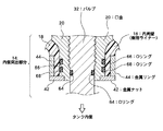
本実施形態のタンク10は、開口部分がタンクの内側に突出している。その内側突出部分14では、略円柱状のバルブ32を取り囲むように口金20がタンク内側に向かって突出している。そして、口金20を取り囲むように内周壁18もタンク内側に向かって突出している。さらに、その内周壁18を取り囲むように金属リング44が設けられ、内周壁18の突出方向の端部から金属ナット42が取り付けられている。金属リング44や金属ナット42は、内周壁(樹脂ライナー)18を支持する支持部材として機能する。なお、内側突出部分14において、バルブ32と口金20との接続面、口金20と内周壁18との接触面には、Oリング(図1において断面矩形状の黒塗り部分)が挿入されている。
As for the tank 10 of this embodiment, the opening part protrudes inside the tank. In the inner projecting
図2は、内側突出部分14の拡大断面図である。内側突出部分14においてバルブ32は円柱状であり、そのバルブ32の側面は、口金20によって取り囲まれている。バルブ32は断面が矩形状の円環状の溝を備えており、その溝に円環状のOリング64が挿入されている。Oリング64は、例えばゴム製などの弾性を備えた部材であり、Oリング64が弾性変形された状態でバルブ32と口金20によって狭持されることで、バルブ32と口金20との間がシールされている。これにより、バルブ32と口金20との間から、タンク内側の燃料ガスなどが漏洩することを確実に阻止している。
FIG. 2 is an enlarged cross-sectional view of the inner projecting
内側突出部分14においては、口金20も円柱状であり、その中心軸に沿って円柱状の開口が設けられ、その開口にバルブ32が挿入されている。そして、口金20の側面は、内周壁18によって取り囲まれている。なお、口金20は断面が矩形状の円環状の溝を備えており、その溝に円環状の二つのOリング66,68が挿入されている。Oリング66,68は、例えばゴム製などの弾性を備えた部材であり、これらOリング66,68が弾性変形された状態で口金20と内周壁18によって狭持されることで、口金20と内周壁18との間がシールされている。これにより、口金20と内周壁18との間から、タンク内側の燃料ガスなどが漏洩することを確実に阻止している。
In the inner projecting
さらに、内側突出部分14において、内周壁18を取り囲むように金属リング44が設けられている。そして、内周壁18のタンク内側の端部から円環状の金属ナット42が取り付けられている。金属リング44や金属ナット42は、内周壁(樹脂ライナー)18を支持する支持部材として機能する。つまり、例えば、Oリング66,68の弾性力によって内周壁(樹脂ライナー)18が開口の径方向の外側へ広げられようとした場合に、金属リング44と金属ナット42によって、径方向の外側への変形が抑制される。このため、樹脂製の内周壁18よりも高い硬度の金属製(ステンレスやアルミニウム製など)の金属リング44と金属ナット42が利用されている。
Furthermore, a
また、例えば、タンクに対して水素などのガスを出し入れする際には、吸熱反応や発熱反応、あるいは外気の使用環境などの影響によって、内側突出部分14に大きな温度変化が発生する。また、金属と樹脂とでは熱膨張率が大きく異なる。このため、金属リング44と金属ナット42が取り付けられていない状態では、温度変化に伴って、内周壁(樹脂ライナー)18と口金20との間に隙間が広がる可能性がある。ところが、本実施形態においては、金属リング44と金属ナット42によって、内周壁(樹脂ライナー)18が、開口の径方向の外側から支持されているため、温度変化があっても、内周壁(樹脂ライナー)18と口金20との間に隙間が広がることがない。
Further, for example, when a gas such as hydrogen is taken in and out of the tank, a large temperature change occurs in the inner projecting
このように、本実施形態では、金属リング44と金属ナット42によって、内周壁18と口金20との間のシール性が格段に高められる。なお、内周壁18の内部に支持部材を埋め込む構成でもよいが、例えば製造面を重視する場合には、図2に示すように内周壁18の外部(径方向外側)に支持部材を設ける構成の方が好ましい。こうすれば、内周壁18の外側に支持部材を設けるだけでよいため構成が簡易であり製造も容易になる。なお、内周壁18の内部にバックアップリングを設けて、さらに内周壁18の外部に金属リング44を設けるようにしてもよい。
Thus, in this embodiment, the sealing performance between the inner
また、金属リング44は、内周壁18の突出方向に沿って、つまりタンクの内側に向かって径が小さくなるテーパ状に形成されてもよい。その場合には、内側突出部分14における内周壁18、口金20、バルブ32、金属ナット42なども、金属リング44のテーパ形状に対応させた形状であることが望ましい。
Further, the
次に、図1に戻り、本実施形態のタンク10の製造方法について説明する。 Next, returning to FIG. 1, a method for manufacturing the tank 10 of the present embodiment will be described.
まず、内側突出部分14に金属リング44をインサート成形した内周壁(樹脂ライナー)18が形成される。なお、内周壁18は、図1に破線で示される接続部70において、図1の上下に二分割されている。ちなみに、図1では下方側が図示省略されており、また上下に分離されて形成された内周壁18は後に接続される。
First, an inner peripheral wall (resin liner) 18 in which a
図示された上方側の内周壁18は、Oリングを介して口金20に密着される。そして内周壁18のタンク内側の端部から円環状の金属ナット42が取り付けられ、これにより口金20と内周壁18との間が確実にシールされる。
The illustrated
図示省略された下方側の内周壁18も上方側と同様に構成され、上下二体の内周壁18がレーザーなどの加熱装置によって接続部70で溶接される。そして、溶接されて一体となった内周壁18の外側に、樹脂(例えばエポキシ樹脂)を含浸させたカーボン繊維をフィラメントワインディングして被覆させ、これを乾燥させることにより、内周壁18と外周壁16の二層構造のタンク本体12が形成される。
The lower inner peripheral wall 18 (not shown) is configured in the same manner as the upper side, and the upper and lower inner
さらに、形成されたタンク本体12の口金20に、Oリングを介してバルブ32が挿入される。なお、バルブ32に換えて、減圧用のレギュレータや、バルブ機能と減圧機能を併せ持つレギュレータバルブが挿入されてもよい。またタンク本体12に、その角部を保護するウレタン製の保護パッド50が取り付けられてもよい。こうして、本実施形態のタンク10が完成する。
Further, a valve 32 is inserted into the formed
次に、本発明の別の好適な実施形態(変形例)について説明する。 Next, another preferred embodiment (modification) of the present invention will be described.
図3は、変形例における内側突出部分14の拡大断面図である。図3に示すタンクは、図1および図2に示したタンクとの比較において、内側突出部分14の内周壁(樹脂ライナー)18を支持する支持部材に相違がある。
FIG. 3 is an enlarged cross-sectional view of the inner projecting
つまり、図1および図2の実施形態では、金属リング44と金属ナット42が支持部材として機能しているのに対し、図3の変形例では、金属リング44と金属ナット42を一体化させた形状に対応するインサートリング46が支持部材として機能している。
That is, in the embodiment of FIGS. 1 and 2, the
支持部材以外の部分において、図3の変形例は、図1および図2の実施形態と同じである。つまり、図3の変形例において、バルブ32は内側突出部分14において円柱状であり、そのバルブ32の側面は、口金20によって取り囲まれている。バルブ32は断面が矩形状の円環状の溝を備えており、その溝に円環状のOリング64が挿入されている。Oリング64は、例えばゴム製などの弾性を備えた部材であり、Oリング64が弾性変形された状態でバルブ32と口金20によって狭持されることで、バルブ32と口金20との間がシールされている。これにより、バルブ32と口金20との間から、タンク内側の燃料ガスなどが漏洩することを確実に阻止している。
In the portion other than the support member, the modification of FIG. 3 is the same as the embodiment of FIGS. 1 and 2. That is, in the modified example of FIG. 3, the valve 32 is cylindrical in the inner protruding
また、内側突出部分14においては、口金20も円柱状であり、その中心軸に沿って円柱状の開口が設けられ、その開口にバルブ32が挿入されている。そして、口金20の側面は、内周壁18によって取り囲まれている。なお、口金20は断面が矩形状の円環状の溝を備えており、その溝に円環状の二つのOリング66,68が挿入されている。Oリング66,68は、例えばゴム製などの弾性を備えた部材であり、これらOリング66,68が弾性変形された状態で口金20と内周壁18によって狭持されることで、口金20と内周壁18との間がシールされている。これにより、口金20と内周壁18との間から、タンク内側の燃料ガスなどが漏洩することを確実に阻止している。
Further, in the inner projecting
そして、図3の変形例では、内側突出部分14において、内周壁18を取り囲むように金属製のインサートリング46が設けられている。インサートリング46は、内周壁(樹脂ライナー)18を支持する支持部材として機能する。つまり、例えば、Oリング66,68の弾性力によって内周壁(樹脂ライナー)18が開口の径方向の外側へ広げられようとした場合に、金属製のインサートリング46によって、径方向の外側への変形が抑制される。
In the modification of FIG. 3, a
さらに、図3の変形例では、インサートリング46と口金20が接触面48において接触している。接触面48は、インサートリング46の径方向の内側に突出した部分の内周面と、円柱状の口金20の外周面とが接触する面である。そして、図3の変形例では、接触面48においてインサートリング46と口金20とが密着している。
Further, in the modification of FIG. 3, the
密着機能を実現するために、口金20は、接触面48における外径寸法が、インサートリング46の内径寸法よりも大きく形成されている。つまり、インサートリング46をインサート成形した内周壁18を形成してから、外径寸法が大きい口金20がインサートリング46内に圧入される。そして、口金20が圧入されることによって、接触面48においてインサートリング46が径方向の外側へ向かって広げられて図3に示す配置関係となる。これにより、接触面48においてインサートリング46が径方向の内側へ向かって口金20を締め付ける力が生じて、インサートリング46と口金20とが密着する。
In order to realize the close contact function, the
ちなみに、接触面48における口金20の外径寸法とインサートリング46の内径寸法の径寸法差を利用した上述の密着機能と、後に説明する口金20とインサートリング46との間の線膨張差による密着機能を併用することにより、接触面48における口金20とインサートリング46の径寸法差を小さくして口金20がインサートリング46内に挿入され易い構成とし、挿入する際の圧入荷重が少なくなるようにしてもよい。
Incidentally, the above-mentioned contact function using the difference in diameter between the outer diameter of the
このように、図3の変形例では、口金20とインサートリング46を締まりばめ勘合させている。そして、接触面48においてインサートリング46と口金20とが密着していることにより、インサートリング46がタンク内側に向かってずれることを防いでいる。なお、この密着機能を実現するために、口金20とインサートリング46は、例えば共にアルミ材料で形成される。あるいは、口金20とインサートリング46が共にSUS材料などで形成されてもよい。
As described above, in the modification of FIG. 3, the
本発明に係るタンクは、内周壁18の外側に、樹脂(例えばエポキシ樹脂)を含浸させたカーボン繊維をフィラメントワインディングして被覆させて、内周壁18と外周壁(図1の符号16)の二層構造となっている。フィラメントワインディング成形後には、加熱硬化処理などが施される。その加熱硬化処理において、樹脂ライナーである内周壁18が伸び、それに伴って、インサートリング46をタンク内側へ向かってずらそうとする力が発生する場合がある。
In the tank according to the present invention, carbon fibers impregnated with resin (for example, epoxy resin) are coated on the outside of the inner
仮に、インサートリング46が口金20に対して自由にスライドすると、加熱硬化処理などに伴う内周壁18の伸びによってインサートリング46がタンク内側へ向かってずれてしまい、口金20と内周壁18との間や外周壁(図1の符号16)と内周壁18との間に隙間が発生してしまう可能性がある。
If the
これに対し、図3の変形例においては、接触面48においてインサートリング46と口金20とが密着していることにより、インサートリング46がタンク内側に向かってずれることを防いでいる。そのため、口金20と内周壁18との間や外周壁と内周壁18との間に隙間が発生することがない。
On the other hand, in the modified example of FIG. 3, the
なお、密着機能を実現するために、口金20とインサートリング46との間の線膨張差を利用してもよい。つまり、インサートリング46を形成する材料よりも線膨張係数が大きい材料で口金20を形成し、加熱によって口金20がインサートリング46よりも径方向外側へ向かって大きく膨張することにより、接触面48においてインサートリング46と口金20とを密着させてもよい。線膨張差を実現する材料の組み合わせとしては、口金20を例えばアルミ材料で形成し、インサートリング46をSUS材料で形成する例を挙げることができる。
In addition, in order to implement | achieve a contact | adherence function, you may utilize the linear expansion difference between the nozzle | cap | die 20 and the
また、インサートリング46のタンク内側に向かうずれを防ぐために、接触面48において、インサートリング46と口金20のうちのいずれか一方に突起を設け、他方にその突起に対応する穴を設けることにより、突起と穴の嵌め合わせによってインサートリング46のずれを防止してもよい。
Further, in order to prevent the
インサートリング46と口金20に関する上述したいくつかの密着構造は、単独で利用されてもよいし、いくつかを組み合わせてもよい。
The several contact | adherence structure mentioned above regarding the
また、インサートリング46と内周壁18との接触面において、インサートリング46側に穴を設けて、その穴に内周壁18が入り込む構成としてもよい。例えば、予め内周側面に径方向に沿って延びる複数の穴が設けられたインサートリング46を利用し、そのインサートリング46をインサート成形した内周壁18を形成する。これより、内周壁18とインサートリング46との間における相対的な回動が抑制され、さらに、インサートリング46と口金20とを密着させておくことにより、内周壁18と口金20との間における相対的な回動も抑制される。なお、インサートリング46は、口金20と螺合するものでもよい。
Moreover, it is good also as a structure which provides a hole in the
以上、本発明の好適な実施形態を説明したが、本実施形態のタンクは、例えば、燃料ガスとなる水素を貯蔵して燃料電池を備えた車両などに搭載される。なお、上述した実施形態は、あらゆる点で単なる例示にすぎず、本発明の範囲を限定するものではない。 Although the preferred embodiment of the present invention has been described above, the tank of this embodiment is mounted on, for example, a vehicle that stores hydrogen serving as fuel gas and includes a fuel cell. The above-described embodiments are merely examples in all respects, and do not limit the scope of the present invention.
10 タンク、18 内周壁(樹脂ライナー)、20 口金、32 バルブ、42 金属ナット、44 金属リング、46 インサートリング。 10 tank, 18 inner peripheral wall (resin liner), 20 base, 32 valve, 42 metal nut, 44 metal ring, 46 insert ring.
Claims (10)
前記周壁を形成し、開口部分においてタンクの内側に突出して開口を取り囲む内側突出部を備えた周壁部材と、
タンクの内側において前記周壁部材の最も外側の表面に設けられ、前記周壁部材の内側突出部を開口の径方向の外側から支持する支持部材と、
前記周壁部材の内側突出部を開口の径方向の内側から支持する口金と、
を有し、
前記支持部材と口金とが接触する接触領域が設けられ、その接触領域において支持部材と口金とが密着することにより、支持部材がタンクの内側に向かってずれることが抑制される、
ことを特徴とするタンク。 A tank with an opening in the peripheral wall,
A peripheral wall member that includes the inner protrusion that forms the peripheral wall and protrudes inside the tank at the opening portion to surround the opening ;
A support member provided on the outermost surface of the peripheral wall member inside the tank, and supporting the inner protrusion of the peripheral wall member from the outside in the radial direction of the opening ;
A base that supports the inner protrusion of the peripheral wall member from the inner side in the radial direction of the opening;
Have
A contact region where the support member and the base come into contact is provided, and the support member and the base are in close contact with each other in the contact region, so that the support member is prevented from being displaced toward the inside of the tank.
A tank characterized by that.
前記支持部材は、前記周壁部材の内側突出部をその突出方向の端部から締め付けるナットを含む、
ことを特徴とするタンク。 The tank according to claim 1, wherein
The support member includes a nut that tightens the inner projecting portion of the peripheral wall member from an end portion in the projecting direction.
A tank characterized by that.
前記支持部材は、前記周壁部材の内側突出部を開口の径方向の外側から取り囲むリングを含む、
ことを特徴とするタンク。 The tank according to claim 2,
The support member includes a ring that surrounds the inner protrusion of the peripheral wall member from the outside in the radial direction of the opening.
A tank characterized by that.
前記支持部材は、前記周壁部材よりも硬度が高い部材である、
ことを特徴とするタンク。 The tank according to claim 3,
The support member is a member having a higher hardness than the peripheral wall member.
A tank characterized by that.
前記周壁部材の内側突出部は樹脂製であり、
前記支持部材に含まれるナットおよびリングのうちの少なくとも一方は金属製である、
ことを特徴とするタンク。 The tank according to claim 4.
The inner projecting portion of the peripheral wall member is made of resin,
At least one of the nut and the ring included in the support member is made of metal.
A tank characterized by that.
前記支持部材のリングと前記口金とによって前記周壁部材の内側突出部が挟持される、
ことを特徴とするタンク。 The tank according to claim 5,
An inner projecting portion of the peripheral wall member is sandwiched by the ring of the support member and the base,
A tank characterized by that.
前記周壁部材の内側突出部と前記口金との間にシール材が設けられる、
ことを特徴とするタンク。 The tank according to claim 6,
A sealing material is provided between the inner protrusion of the peripheral wall member and the base.
A tank characterized by that.
前記支持部材のリングは、前記内側突出部の突出方向に沿ってタンクの内側に向かって径が小さくなるテーパ形状である、
ことを特徴とするタンク。 The tank according to claim 7,
The ring of the support member has a tapered shape whose diameter decreases toward the inside of the tank along the protruding direction of the inner protruding portion.
A tank characterized by that.
前記支持部材は、前記開口を取り囲む円周に沿って形成されて前記開口の径方向の内側に向かって突出した突出面を備え、
前記口金は、支持部材の突出面に対応する側面部分を備え、その側面部分における外径寸法が支持部材の突出面における内径寸法よりも大きく形成され、
支持部材に口金が挿入されて支持部材の突出面と口金の側面部分が接触して接触領域として機能することにより、その接触領域において支持部材の突出面によって口金の側面部分が締め付けられて支持部材と口金とが密着される、
ことを特徴とするタンク。 The tank according to claim 1 , wherein
The support member includes a protruding surface that is formed along a circumference surrounding the opening and protrudes inward in the radial direction of the opening;
The base includes a side surface portion corresponding to the protruding surface of the support member, and an outer diameter size of the side surface portion is formed larger than an inner diameter size of the protruding surface of the support member,
When the base is inserted into the support member and the projecting surface of the support member and the side surface portion of the base come into contact with each other and function as a contact region, the side surface portion of the base is tightened by the projecting surface of the support member in the contact region. And the base are in close contact,
A tank characterized by that.
前記口金は、前記支持部材よりも線膨張係数の大きい材料で形成され、
加熱によって口金が支持部材よりも大きく膨張することにより前記接触領域で支持部材と口金とが密着される、
ことを特徴とするタンク。
The tank according to claim 1 , wherein
The base is formed of a material having a larger linear expansion coefficient than the support member,
The support member and the base are brought into close contact with each other in the contact area by expanding the base larger than the support member by heating.
A tank characterized by that.
Priority Applications (5)
| Application Number | Priority Date | Filing Date | Title |
|---|---|---|---|
| JP2006060484A JP4935117B2 (en) | 2005-11-08 | 2006-03-07 | tank |
| PCT/JP2006/322517 WO2007055343A1 (en) | 2005-11-08 | 2006-11-07 | Tank |
| DE112006003013T DE112006003013B4 (en) | 2005-11-08 | 2006-11-07 | tank |
| CN2006800405942A CN101300447B (en) | 2005-11-08 | 2006-11-07 | Tank |
| US11/992,957 US20090255940A1 (en) | 2005-11-08 | 2006-11-07 | Tank |
Applications Claiming Priority (3)
| Application Number | Priority Date | Filing Date | Title |
|---|---|---|---|
| JP2005323052 | 2005-11-08 | ||
| JP2005323052 | 2005-11-08 | ||
| JP2006060484A JP4935117B2 (en) | 2005-11-08 | 2006-03-07 | tank |
Publications (3)
| Publication Number | Publication Date |
|---|---|
| JP2007155116A JP2007155116A (en) | 2007-06-21 |
| JP2007155116A5 JP2007155116A5 (en) | 2008-11-27 |
| JP4935117B2 true JP4935117B2 (en) | 2012-05-23 |
Family
ID=38023336
Family Applications (1)
| Application Number | Title | Priority Date | Filing Date |
|---|---|---|---|
| JP2006060484A Active JP4935117B2 (en) | 2005-11-08 | 2006-03-07 | tank |
Country Status (5)
| Country | Link |
|---|---|
| US (1) | US20090255940A1 (en) |
| JP (1) | JP4935117B2 (en) |
| CN (1) | CN101300447B (en) |
| DE (1) | DE112006003013B4 (en) |
| WO (1) | WO2007055343A1 (en) |
Cited By (1)
| Publication number | Priority date | Publication date | Assignee | Title |
|---|---|---|---|---|
| KR20180071548A (en) * | 2016-12-20 | 2018-06-28 | 현대자동차주식회사 | High pressure tank having reinforced boss-part |
Families Citing this family (66)
| Publication number | Priority date | Publication date | Assignee | Title |
|---|---|---|---|---|
| JP4875915B2 (en) * | 2006-03-29 | 2012-02-15 | 富士重工業株式会社 | Pressure vessel |
| JP4457359B2 (en) * | 2006-12-13 | 2010-04-28 | トヨタ自動車株式会社 | Pressure vessel |
| JP5018100B2 (en) * | 2007-01-22 | 2012-09-05 | トヨタ自動車株式会社 | Pressure vessel and pressure vessel manufacturing method |
| JP5169473B2 (en) * | 2008-05-19 | 2013-03-27 | 株式会社ジェイテクト | Fluid supply valve assembly device |
| US20100124688A1 (en) * | 2008-11-18 | 2010-05-20 | Eveready Battery Company, Inc. | Regulator Valve for a Fluid Consuming Battery |
| JP5375296B2 (en) * | 2009-04-16 | 2013-12-25 | トヨタ自動車株式会社 | Hydrogen tank |
| JP5471143B2 (en) * | 2009-08-07 | 2014-04-16 | スズキ株式会社 | High pressure gas tank system |
| JP5083289B2 (en) * | 2009-10-19 | 2012-11-28 | トヨタ自動車株式会社 | Tank and tank manufacturing method |
| DE102009049948B4 (en) * | 2009-10-19 | 2012-02-02 | Kautex Maschinenbau Gmbh | pressure vessel |
| JP5865267B2 (en) * | 2010-02-26 | 2016-02-17 | ラクスファー カナダ リミテッド | Protrusion prevention seal system for the exit of compressed gas cylinders lined with plastic |
| US8523002B2 (en) * | 2010-02-26 | 2013-09-03 | GM Global Technology Operations LLC | Embedded reinforcement sleeve for a pressure vessel |
| DE102010018700B4 (en) * | 2010-04-29 | 2019-05-09 | Magna Steyr Fahrzeugtechnik Ag & Co. Kg | pressure vessel |
| EP2646736B1 (en) * | 2010-11-30 | 2021-06-30 | Advanced Lightweight Engineering B.V. | Vessel |
| JP5869362B2 (en) * | 2012-02-15 | 2016-02-24 | 高圧ガス保安協会 | Pressure vessel unit |
| JP5904081B2 (en) * | 2012-10-05 | 2016-04-13 | トヨタ自動車株式会社 | Pressure vessel and production method thereof |
| US9316357B2 (en) * | 2012-11-23 | 2016-04-19 | ILJIN Composites Co., Ltd. | Pressure vessel |
| DE102014103390B4 (en) | 2013-03-14 | 2019-07-04 | GM Global Technology Operations LLC (n. d. Ges. d. Staates Delaware) | Seal assembly and the seal assembly comprising pressure vessel |
| US8978920B2 (en) * | 2013-03-14 | 2015-03-17 | GM Global Technology Operations LLC | Sealing assemblies and pressurized fluid vessels including the sealing assemblies |
| JP6235797B2 (en) * | 2013-06-06 | 2017-11-22 | 八千代工業株式会社 | Pressure vessel |
| US8881932B1 (en) * | 2013-06-25 | 2014-11-11 | Quantum Fuel Systems Technology Worldwide, Inc. | Adapterless closure assembly for composite pressure vessels |
| MX2017000709A (en) * | 2014-07-17 | 2017-10-16 | Faber Ind Spa | Pressure vessel. |
| USD746942S1 (en) | 2014-10-21 | 2016-01-05 | Advanced Lightweight Engineering B.V. | Low weight pressure vessel |
| JP6601379B2 (en) | 2016-12-06 | 2019-11-06 | トヨタ自動車株式会社 | Pressure vessel and method for manufacturing pressure vessel |
| JP6597668B2 (en) * | 2017-02-23 | 2019-10-30 | トヨタ自動車株式会社 | Pressure vessel |
| DE102017204713A1 (en) | 2017-03-21 | 2018-09-27 | Volkswagen Aktiengesellschaft | Container for storing a fluid medium and vehicle with such a container |
| DE102017204710A1 (en) | 2017-03-21 | 2018-09-27 | Volkswagen Aktiengesellschaft | Container for storing a fluid medium and vehicle with such a container |
| DE102017204707A1 (en) | 2017-03-21 | 2018-09-27 | Volkswagen Aktiengesellschaft | Container for storing a fluid medium and vehicle with such a container |
| WO2018212647A1 (en) | 2017-05-15 | 2018-11-22 | Advanced Lightweight Engineering B.V. | Pressure vessel for the storage of pressurized fluids and vehicle comprising such a pressure vessel |
| US10753474B2 (en) | 2017-11-07 | 2020-08-25 | Hexagon Technology As | Blind boss fitting with redundant seal |
| JP7311243B2 (en) | 2017-12-28 | 2023-07-19 | トヨタ自動車株式会社 | High pressure tank with protector |
| CN108131555B (en) * | 2017-12-31 | 2023-07-25 | 亚普汽车部件股份有限公司 | High-pressure composite container with sealing structure |
| FR3089160B1 (en) | 2018-11-30 | 2020-12-04 | Plastic Omnium Advanced Innovation & Res | Internal casing for pressurized fluid storage tank for motor vehicle |
| DE102019210515A1 (en) * | 2019-07-17 | 2021-01-21 | Robert Bosch Gmbh | Tank device for storing a gaseous medium |
| FR3102530B1 (en) * | 2019-10-24 | 2023-09-01 | Faurecia Systemes Dechappement | Pressurized gas tank |
| DE102019007550A1 (en) * | 2019-10-30 | 2021-05-06 | Daimler Ag | Pressurized gas container |
| FR3106192B1 (en) * | 2020-01-15 | 2023-11-24 | Faurecia Systemes Dechappement | Tank, particularly for hydrogen, with improved sealing |
| EP3919805B1 (en) * | 2020-06-05 | 2023-11-29 | Magna Energy Storage Systems GesmbH | High pressure vessel |
| CN111649226A (en) * | 2020-06-15 | 2020-09-11 | 安徽绿动能源有限公司 | Plastic liner fiber fully-wound gas cylinder and manufacturing method thereof |
| DE102020207501A1 (en) | 2020-06-17 | 2021-12-23 | Robert Bosch Gesellschaft mit beschränkter Haftung | Valve device for a pressurized container and method of making a valve device |
| DE102020208843A1 (en) | 2020-07-15 | 2022-01-20 | Robert Bosch Gesellschaft mit beschränkter Haftung | Valve socket for a pressurized container, valve device and method of manufacturing a valve socket |
| DE102020209771A1 (en) | 2020-08-04 | 2022-02-10 | Robert Bosch Gesellschaft mit beschränkter Haftung | Valve assembly for a pressurized container and method of making a valve assembly for a pressurized container |
| CN111963888B (en) * | 2020-08-28 | 2022-11-04 | 亚普汽车部件股份有限公司 | Sealing structure of high-pressure gas cylinder with plastic inner container |
| DE102020213911A1 (en) | 2020-11-05 | 2022-05-05 | Robert Bosch Gesellschaft mit beschränkter Haftung | Tank device for a fuel cell system and method for producing a tank device for a fuel cell system |
| DE102020213907A1 (en) | 2020-11-05 | 2022-05-05 | Robert Bosch Gesellschaft mit beschränkter Haftung | Thermal relief device for a gas tank and method of manufacturing a thermal relief device for a gas tank |
| DE102020212078A1 (en) | 2020-11-13 | 2022-05-19 | Robert Bosch Gesellschaft mit beschränkter Haftung | Pressure storage device for storing a medium and method for operating a pressure storage device |
| DE102020214316A1 (en) | 2020-11-13 | 2022-05-19 | Robert Bosch Gesellschaft mit beschränkter Haftung | Fuel delivery device for delivering fuel for a fuel cell system, fuel cell system and method for operating a fuel delivery device for delivering fuel for a fuel cell system |
| CN112833329A (en) * | 2021-01-27 | 2021-05-25 | 中材科技(苏州)有限公司 | Bottle mouth structure for nonmetal liner fiber reinforced high-pressure gas bottle |
| DE102021201176A1 (en) | 2021-02-09 | 2022-08-11 | Robert Bosch Gesellschaft mit beschränkter Haftung | Tank device for storing a gaseous medium for a vehicle and method for operating a tank device for storing a gaseous medium for a vehicle |
| DE102021202413A1 (en) | 2021-03-12 | 2022-09-15 | Robert Bosch Gesellschaft mit beschränkter Haftung | Measuring device for determining gas permeability through a sample and method for operating a measuring device for determining gas permeability through a sample |
| DE102021202696A1 (en) | 2021-03-19 | 2022-09-22 | Robert Bosch Gesellschaft mit beschränkter Haftung | Tank device for storing gas fuel for a vehicle and method for operating a tank device for storing gas fuel for a vehicle |
| DE102021107165B4 (en) | 2021-03-23 | 2023-08-24 | Worthington Cylinders Gmbh | Final boss seal |
| DE102021203429A1 (en) | 2021-04-07 | 2022-10-13 | Robert Bosch Gesellschaft mit beschränkter Haftung | Tank device for storing a gaseous medium for a vehicle, line system for supplying a vehicle with fuel and method for operating a line system and/or a tank device |
| EP4083495A1 (en) | 2021-04-29 | 2022-11-02 | Robert Bosch GmbH | Connecting device for connecting a hydrogen storage tank and a supply line for the hydrogen storage tank, hydrogen storage system and method for connecting a hydrogen storage tank with a supply line |
| DE102021204897A1 (en) | 2021-05-14 | 2022-11-17 | Robert Bosch Gesellschaft mit beschränkter Haftung | Tank valve device for at least one tank container, tank device for storing a fuel and method for operating a tank device |
| DE102021205557A1 (en) | 2021-06-01 | 2022-12-01 | Robert Bosch Gesellschaft mit beschränkter Haftung | Recirculation device for hydrogen supply in a fuel cell and method for operating a recirculation device for hydrogen supply in a fuel cell |
| DE102021205566A1 (en) | 2021-06-01 | 2022-12-01 | Robert Bosch Gesellschaft mit beschränkter Haftung | Control device for hydrogen supply in a fuel cell, fuel cell device and method for operating a control device for hydrogen supply in a fuel cell |
| DE102021206257A1 (en) | 2021-06-18 | 2022-12-22 | Robert Bosch Gesellschaft mit beschränkter Haftung | Tank valve device for at least one tank container, tank device for a fuel and method for operating a tank device for a fuel |
| DE102021207487A1 (en) | 2021-07-14 | 2023-01-19 | Robert Bosch Gesellschaft mit beschränkter Haftung | Fuel delivery device for delivering a fuel for a fuel cell system and method for operating a fuel delivery device for delivering a fuel for a fuel cell system |
| US11732843B2 (en) * | 2021-07-19 | 2023-08-22 | Caterpillar Inc. | On-tank regulator for high-pressure tank |
| DE102021211085A1 (en) | 2021-10-01 | 2023-04-06 | Robert Bosch Gesellschaft mit beschränkter Haftung | Refueling device for a vehicle powered by hydrogen or a gaseous fuel and method for operating a refueling device for a vehicle powered by hydrogen or a gaseous fuel |
| DE102021211060A1 (en) | 2021-10-01 | 2023-04-06 | Robert Bosch Gesellschaft mit beschränkter Haftung | Fan device for a hydrogen circuit in a fuel cell device and method for operating a fan device |
| DE102021214838A1 (en) | 2021-12-21 | 2023-06-22 | Robert Bosch Gesellschaft mit beschränkter Haftung | Compressor device for a hydrogen feed and method of manufacturing a compressor device for a hydrogen feed |
| KR20230096211A (en) * | 2021-12-22 | 2023-06-30 | 일진하이솔루스 주식회사 | Manufacturing Methods of Integral Type Sealing Gasket For High Pressure Vessel |
| DE102022200233A1 (en) | 2022-01-12 | 2023-07-13 | Robert Bosch Gesellschaft mit beschränkter Haftung | Metering device for a hydrogen circuit for a fuel cell device and method for operating a metering device for a hydrogen circuit for a fuel cell device |
| DE102022200368A1 (en) | 2022-01-14 | 2023-07-20 | Robert Bosch Gesellschaft mit beschränkter Haftung | Method for operating a fuel cell device and fuel cell device |
| DE102022208131A1 (en) | 2022-08-04 | 2024-02-15 | Mahle International Gmbh | pressure vessel |
Family Cites Families (42)
| Publication number | Priority date | Publication date | Assignee | Title |
|---|---|---|---|---|
| US3182110A (en) * | 1958-11-05 | 1965-05-04 | White Consolidated Ind Inc | Method and apparatus for making fiber glass tank |
| US3137405A (en) * | 1961-12-18 | 1964-06-16 | North American Aviation Inc | Pressure vessel |
| US3419180A (en) * | 1966-12-07 | 1968-12-31 | Halliburton Co | Closure assembly for high-pressure, high-temperature vessels |
| US3917115A (en) * | 1974-03-15 | 1975-11-04 | Amf Inc | Diving cylinder with liner |
| US4537329A (en) * | 1984-04-02 | 1985-08-27 | Culligan International Company | Tank lining system |
| BE902543A (en) * | 1985-05-30 | 1985-09-16 | Duktrad Internat | Plastics pressure vessel neck-sealing ring - has annular inner section of larger dia. than opening with screw thread |
| JPS62255698A (en) * | 1986-04-25 | 1987-11-07 | Agency Of Ind Science & Technol | Attaching of accessary to container made of composite material |
| US5429845A (en) * | 1992-01-10 | 1995-07-04 | Brunswick Corporation | Boss for a filament wound pressure vessel |
| US5253778A (en) * | 1992-01-28 | 1993-10-19 | Edo Canada Ltd. | Fluid pressure vessel boss-liner attachment system |
| US5494188A (en) * | 1992-01-28 | 1996-02-27 | Edo Canada Ltd. | Fluid pressure vessel boss-liner attachment system with liner/exterior mechanism direct coupling |
| US5316611A (en) * | 1992-07-06 | 1994-05-31 | Edo Corporation, Fiber Science Division | Method of forming reusable seamless mandrels for the fabrication of hollow fiber wound vessels |
| US5287988A (en) * | 1993-02-03 | 1994-02-22 | Brunswick Corporation | Metal-lined pressure vessel |
| US5476189A (en) * | 1993-12-03 | 1995-12-19 | Duvall; Paul F. | Pressure vessel with damage mitigating system |
| US5518141A (en) * | 1994-01-24 | 1996-05-21 | Newhouse; Norman L. | Pressure vessel with system to prevent liner separation |
| US5388720A (en) * | 1994-04-15 | 1995-02-14 | Essef Corporation | Flanged diffuser and air cell retainer for pressure vessel |
| JPH08219387A (en) * | 1995-02-15 | 1996-08-30 | Toray Ind Inc | Gas cylinder |
| US6190481B1 (en) * | 1995-12-04 | 2001-02-20 | Toray Industries, Inc. | Pressure vessel and process for producing the same |
| US5568878A (en) * | 1996-01-11 | 1996-10-29 | Essef Corporation | Filament wound pressure vessel having a reinforced access opening |
| BR9600459A (en) * | 1996-01-17 | 1998-03-03 | Fibrasynthetica Do Brasil Comp | Plastic container for pressurized fluids |
| US6089399A (en) * | 1997-01-14 | 2000-07-18 | Chatwins Group, Inc. | Inert-metal lined, seamless steel-body cylinder |
| US5938209A (en) * | 1997-02-14 | 1999-08-17 | Alternative Fuel Systems, Inc. | Seal system for fluid pressure vessels |
| JPH1113995A (en) * | 1997-06-23 | 1999-01-22 | Kobe Steel Ltd | Socket structure of pressure container of plastic liner frp(fiber reinforced plastics) |
| DE19751411C1 (en) * | 1997-11-14 | 1999-01-14 | Mannesmann Ag | Composite fibre-reinforced pressurised gas tank including liner with end neck sections |
| US5979692A (en) * | 1998-03-13 | 1999-11-09 | Harsco Corporation | Boss for composite pressure vessel having polymeric liner |
| US6135308A (en) * | 1998-06-26 | 2000-10-24 | Industrial Technology Research Institute | Boss for a filament wound pressure vessel |
| DE60010047T2 (en) * | 1999-02-16 | 2005-04-28 | Alliant Techsystems Inc., Hopkins | CLOSURE FOR TANKS WITH INTERNAL SHEET, AND VEHICLES EQUIPPED THEREwith |
| JP3523802B2 (en) * | 1999-04-07 | 2004-04-26 | 豊田合成株式会社 | Pressure vessel |
| DE10000705A1 (en) * | 2000-01-10 | 2001-07-19 | Ralph Funck | Pressure container for storing liquid and / or gaseous media under pressure consisting of a plastic core container which is reinforced with fiber-reinforced plastics and process for its production |
| JP4077636B2 (en) | 2002-02-22 | 2008-04-16 | 愛三工業株式会社 | High pressure tank |
| US7032768B2 (en) * | 2002-04-04 | 2006-04-25 | Felbaum John W | Inert-metal lined steel-bodied vessel end-closure device |
| DE10360953B4 (en) * | 2002-12-27 | 2011-04-07 | Toyoda Gosei Co., Ltd., Nishikasugai-gun | pressure vessel |
| KR100589450B1 (en) * | 2003-01-24 | 2006-06-14 | 가부시키가이샤 도요다 지도숏키 | High-pressure tank |
| JP4219194B2 (en) * | 2003-03-11 | 2009-02-04 | 株式会社豊田自動織機 | Pressure vessel |
| DE10329990B3 (en) * | 2003-07-02 | 2005-04-21 | Benteler Automobiltechnik Gmbh | Pressure gas tank |
| US7100262B2 (en) * | 2003-07-08 | 2006-09-05 | Polymer & Steel Technologies Holding Company Llc | Method of forming filament-reinforced composite thermoplastic pressure vessel fitting assembly |
| JP4525021B2 (en) * | 2003-07-31 | 2010-08-18 | トヨタ自動車株式会社 | tank |
| JP4736312B2 (en) * | 2003-07-31 | 2011-07-27 | トヨタ自動車株式会社 | tank |
| KR100469636B1 (en) * | 2004-03-11 | 2005-02-02 | 주식회사 케이시알 | The high gas-tighten metallic nozzle-boss for the high pressure composite vessel |
| JP4715841B2 (en) * | 2005-02-02 | 2011-07-06 | トヨタ自動車株式会社 | High pressure tank seal structure |
| JP4605549B2 (en) * | 2005-06-06 | 2011-01-05 | トヨタ自動車株式会社 | Manufacturing method of pressure vessel |
| US7731051B2 (en) * | 2005-07-13 | 2010-06-08 | Gm Global Technology Operations, Inc. | Hydrogen pressure tank including an inner liner with an outer annular flange |
| US7556171B2 (en) * | 2005-11-17 | 2009-07-07 | Toyota Jidosha Kabushiki Kaisha | Tank |
-
2006
- 2006-03-07 JP JP2006060484A patent/JP4935117B2/en active Active
- 2006-11-07 DE DE112006003013T patent/DE112006003013B4/en active Active
- 2006-11-07 US US11/992,957 patent/US20090255940A1/en not_active Abandoned
- 2006-11-07 WO PCT/JP2006/322517 patent/WO2007055343A1/en active Application Filing
- 2006-11-07 CN CN2006800405942A patent/CN101300447B/en active Active
Cited By (2)
| Publication number | Priority date | Publication date | Assignee | Title |
|---|---|---|---|---|
| KR20180071548A (en) * | 2016-12-20 | 2018-06-28 | 현대자동차주식회사 | High pressure tank having reinforced boss-part |
| KR102463415B1 (en) | 2016-12-20 | 2022-11-03 | 현대자동차주식회사 | High pressure tank having reinforced boss-part |
Also Published As
| Publication number | Publication date |
|---|---|
| DE112006003013B4 (en) | 2011-07-28 |
| WO2007055343A1 (en) | 2007-05-18 |
| JP2007155116A (en) | 2007-06-21 |
| CN101300447A (en) | 2008-11-05 |
| CN101300447B (en) | 2011-05-11 |
| DE112006003013T5 (en) | 2008-09-25 |
| US20090255940A1 (en) | 2009-10-15 |
Similar Documents
| Publication | Publication Date | Title |
|---|---|---|
| JP4935117B2 (en) | tank | |
| US7556171B2 (en) | Tank | |
| JP4392804B2 (en) | Pressure vessel | |
| JP2007146946A (en) | High-pressure tank | |
| CA2558415C (en) | Self-energized gasket and manufacturing method therefor | |
| JPH09257172A (en) | Fitting | |
| US10487982B2 (en) | High-pressure vessel | |
| JP7253330B2 (en) | Gasket mounting structure and gasket | |
| JP2008232435A (en) | Seal for sensor packed small | |
| JP2005127388A (en) | High pressure container and its manufacturing method | |
| JP7017990B2 (en) | Gasket mounting structure for fluid devices | |
| WO2019163690A1 (en) | Structure for mounting gasket to block | |
| JP4525021B2 (en) | tank | |
| JP2019210986A (en) | Gasket mounting structure and gasket | |
| JP2011085230A (en) | Tank and method of manufacturing the same | |
| JP2008014342A (en) | Tank | |
| JP2008175341A (en) | Pressure vessel and manufacturing method for pressure vessel | |
| JP2011017379A (en) | Gas tank | |
| JP7090810B2 (en) | Sealing device | |
| JP6675169B2 (en) | Pressure vessel sealed structure | |
| JP6658497B2 (en) | High pressure tank | |
| JP2010065810A (en) | Seal structure | |
| JP2005240834A (en) | Bellows type accumulator | |
| JP5404147B2 (en) | Fitting for flexible tube | |
| JP2023061716A (en) | sealing device |
Legal Events
| Date | Code | Title | Description |
|---|---|---|---|
| A521 | Written amendment |
Free format text: JAPANESE INTERMEDIATE CODE: A523 Effective date: 20081015 |
|
| A621 | Written request for application examination |
Free format text: JAPANESE INTERMEDIATE CODE: A621 Effective date: 20081015 |
|
| A131 | Notification of reasons for refusal |
Free format text: JAPANESE INTERMEDIATE CODE: A131 Effective date: 20110628 |
|
| A521 | Written amendment |
Free format text: JAPANESE INTERMEDIATE CODE: A523 Effective date: 20110823 |
|
| TRDD | Decision of grant or rejection written | ||
| A01 | Written decision to grant a patent or to grant a registration (utility model) |
Free format text: JAPANESE INTERMEDIATE CODE: A01 Effective date: 20120124 |
|
| A01 | Written decision to grant a patent or to grant a registration (utility model) |
Free format text: JAPANESE INTERMEDIATE CODE: A01 |
|
| A61 | First payment of annual fees (during grant procedure) |
Free format text: JAPANESE INTERMEDIATE CODE: A61 Effective date: 20120206 |
|
| FPAY | Renewal fee payment (event date is renewal date of database) |
Free format text: PAYMENT UNTIL: 20150302 Year of fee payment: 3 |
|
| R151 | Written notification of patent or utility model registration |
Ref document number: 4935117 Country of ref document: JP Free format text: JAPANESE INTERMEDIATE CODE: R151 |
|
| FPAY | Renewal fee payment (event date is renewal date of database) |
Free format text: PAYMENT UNTIL: 20150302 Year of fee payment: 3 |