JP6235797B2 - Pressure vessel - Google Patents
Pressure vessel Download PDFInfo
- Publication number
- JP6235797B2 JP6235797B2 JP2013119749A JP2013119749A JP6235797B2 JP 6235797 B2 JP6235797 B2 JP 6235797B2 JP 2013119749 A JP2013119749 A JP 2013119749A JP 2013119749 A JP2013119749 A JP 2013119749A JP 6235797 B2 JP6235797 B2 JP 6235797B2
- Authority
- JP
- Japan
- Prior art keywords
- base
- pressure vessel
- liner
- attachment member
- seal member
- Prior art date
- Legal status (The legal status is an assumption and is not a legal conclusion. Google has not performed a legal analysis and makes no representation as to the accuracy of the status listed.)
- Active
Links
Images


Classifications
-
- F—MECHANICAL ENGINEERING; LIGHTING; HEATING; WEAPONS; BLASTING
- F17—STORING OR DISTRIBUTING GASES OR LIQUIDS
- F17C—VESSELS FOR CONTAINING OR STORING COMPRESSED, LIQUEFIED OR SOLIDIFIED GASES; FIXED-CAPACITY GAS-HOLDERS; FILLING VESSELS WITH, OR DISCHARGING FROM VESSELS, COMPRESSED, LIQUEFIED, OR SOLIDIFIED GASES
- F17C13/00—Details of vessels or of the filling or discharging of vessels
- F17C13/06—Closures, e.g. cap, breakable member
-
- F—MECHANICAL ENGINEERING; LIGHTING; HEATING; WEAPONS; BLASTING
- F17—STORING OR DISTRIBUTING GASES OR LIQUIDS
- F17C—VESSELS FOR CONTAINING OR STORING COMPRESSED, LIQUEFIED OR SOLIDIFIED GASES; FIXED-CAPACITY GAS-HOLDERS; FILLING VESSELS WITH, OR DISCHARGING FROM VESSELS, COMPRESSED, LIQUEFIED, OR SOLIDIFIED GASES
- F17C1/00—Pressure vessels, e.g. gas cylinder, gas tank, replaceable cartridge
- F17C1/02—Pressure vessels, e.g. gas cylinder, gas tank, replaceable cartridge involving reinforcing arrangements
-
- F—MECHANICAL ENGINEERING; LIGHTING; HEATING; WEAPONS; BLASTING
- F17—STORING OR DISTRIBUTING GASES OR LIQUIDS
- F17C—VESSELS FOR CONTAINING OR STORING COMPRESSED, LIQUEFIED OR SOLIDIFIED GASES; FIXED-CAPACITY GAS-HOLDERS; FILLING VESSELS WITH, OR DISCHARGING FROM VESSELS, COMPRESSED, LIQUEFIED, OR SOLIDIFIED GASES
- F17C2201/00—Vessel construction, in particular geometry, arrangement or size
- F17C2201/01—Shape
- F17C2201/0104—Shape cylindrical
- F17C2201/0109—Shape cylindrical with exteriorly curved end-piece
-
- F—MECHANICAL ENGINEERING; LIGHTING; HEATING; WEAPONS; BLASTING
- F17—STORING OR DISTRIBUTING GASES OR LIQUIDS
- F17C—VESSELS FOR CONTAINING OR STORING COMPRESSED, LIQUEFIED OR SOLIDIFIED GASES; FIXED-CAPACITY GAS-HOLDERS; FILLING VESSELS WITH, OR DISCHARGING FROM VESSELS, COMPRESSED, LIQUEFIED, OR SOLIDIFIED GASES
- F17C2201/00—Vessel construction, in particular geometry, arrangement or size
- F17C2201/05—Size
- F17C2201/056—Small (<1 m3)
-
- F—MECHANICAL ENGINEERING; LIGHTING; HEATING; WEAPONS; BLASTING
- F17—STORING OR DISTRIBUTING GASES OR LIQUIDS
- F17C—VESSELS FOR CONTAINING OR STORING COMPRESSED, LIQUEFIED OR SOLIDIFIED GASES; FIXED-CAPACITY GAS-HOLDERS; FILLING VESSELS WITH, OR DISCHARGING FROM VESSELS, COMPRESSED, LIQUEFIED, OR SOLIDIFIED GASES
- F17C2201/00—Vessel construction, in particular geometry, arrangement or size
- F17C2201/05—Size
- F17C2201/058—Size portable (<30 l)
-
- F—MECHANICAL ENGINEERING; LIGHTING; HEATING; WEAPONS; BLASTING
- F17—STORING OR DISTRIBUTING GASES OR LIQUIDS
- F17C—VESSELS FOR CONTAINING OR STORING COMPRESSED, LIQUEFIED OR SOLIDIFIED GASES; FIXED-CAPACITY GAS-HOLDERS; FILLING VESSELS WITH, OR DISCHARGING FROM VESSELS, COMPRESSED, LIQUEFIED, OR SOLIDIFIED GASES
- F17C2203/00—Vessel construction, in particular walls or details thereof
- F17C2203/06—Materials for walls or layers thereof; Properties or structures of walls or their materials
- F17C2203/0602—Wall structures; Special features thereof
- F17C2203/0604—Liners
-
- F—MECHANICAL ENGINEERING; LIGHTING; HEATING; WEAPONS; BLASTING
- F17—STORING OR DISTRIBUTING GASES OR LIQUIDS
- F17C—VESSELS FOR CONTAINING OR STORING COMPRESSED, LIQUEFIED OR SOLIDIFIED GASES; FIXED-CAPACITY GAS-HOLDERS; FILLING VESSELS WITH, OR DISCHARGING FROM VESSELS, COMPRESSED, LIQUEFIED, OR SOLIDIFIED GASES
- F17C2203/00—Vessel construction, in particular walls or details thereof
- F17C2203/06—Materials for walls or layers thereof; Properties or structures of walls or their materials
- F17C2203/0602—Wall structures; Special features thereof
- F17C2203/0612—Wall structures
- F17C2203/0614—Single wall
- F17C2203/0619—Single wall with two layers
-
- F—MECHANICAL ENGINEERING; LIGHTING; HEATING; WEAPONS; BLASTING
- F17—STORING OR DISTRIBUTING GASES OR LIQUIDS
- F17C—VESSELS FOR CONTAINING OR STORING COMPRESSED, LIQUEFIED OR SOLIDIFIED GASES; FIXED-CAPACITY GAS-HOLDERS; FILLING VESSELS WITH, OR DISCHARGING FROM VESSELS, COMPRESSED, LIQUEFIED, OR SOLIDIFIED GASES
- F17C2203/00—Vessel construction, in particular walls or details thereof
- F17C2203/06—Materials for walls or layers thereof; Properties or structures of walls or their materials
- F17C2203/0634—Materials for walls or layers thereof
- F17C2203/0658—Synthetics
- F17C2203/066—Plastics
-
- F—MECHANICAL ENGINEERING; LIGHTING; HEATING; WEAPONS; BLASTING
- F17—STORING OR DISTRIBUTING GASES OR LIQUIDS
- F17C—VESSELS FOR CONTAINING OR STORING COMPRESSED, LIQUEFIED OR SOLIDIFIED GASES; FIXED-CAPACITY GAS-HOLDERS; FILLING VESSELS WITH, OR DISCHARGING FROM VESSELS, COMPRESSED, LIQUEFIED, OR SOLIDIFIED GASES
- F17C2203/00—Vessel construction, in particular walls or details thereof
- F17C2203/06—Materials for walls or layers thereof; Properties or structures of walls or their materials
- F17C2203/0634—Materials for walls or layers thereof
- F17C2203/0658—Synthetics
- F17C2203/0663—Synthetics in form of fibers or filaments
-
- F—MECHANICAL ENGINEERING; LIGHTING; HEATING; WEAPONS; BLASTING
- F17—STORING OR DISTRIBUTING GASES OR LIQUIDS
- F17C—VESSELS FOR CONTAINING OR STORING COMPRESSED, LIQUEFIED OR SOLIDIFIED GASES; FIXED-CAPACITY GAS-HOLDERS; FILLING VESSELS WITH, OR DISCHARGING FROM VESSELS, COMPRESSED, LIQUEFIED, OR SOLIDIFIED GASES
- F17C2205/00—Vessel construction, in particular mounting arrangements, attachments or identifications means
- F17C2205/03—Fluid connections, filters, valves, closure means or other attachments
- F17C2205/0302—Fittings, valves, filters, or components in connection with the gas storage device
- F17C2205/0305—Bosses, e.g. boss collars
-
- F—MECHANICAL ENGINEERING; LIGHTING; HEATING; WEAPONS; BLASTING
- F17—STORING OR DISTRIBUTING GASES OR LIQUIDS
- F17C—VESSELS FOR CONTAINING OR STORING COMPRESSED, LIQUEFIED OR SOLIDIFIED GASES; FIXED-CAPACITY GAS-HOLDERS; FILLING VESSELS WITH, OR DISCHARGING FROM VESSELS, COMPRESSED, LIQUEFIED, OR SOLIDIFIED GASES
- F17C2209/00—Vessel construction, in particular methods of manufacturing
- F17C2209/21—Shaping processes
- F17C2209/2109—Moulding
- F17C2209/2127—Moulding by blowing
-
- F—MECHANICAL ENGINEERING; LIGHTING; HEATING; WEAPONS; BLASTING
- F17—STORING OR DISTRIBUTING GASES OR LIQUIDS
- F17C—VESSELS FOR CONTAINING OR STORING COMPRESSED, LIQUEFIED OR SOLIDIFIED GASES; FIXED-CAPACITY GAS-HOLDERS; FILLING VESSELS WITH, OR DISCHARGING FROM VESSELS, COMPRESSED, LIQUEFIED, OR SOLIDIFIED GASES
- F17C2209/00—Vessel construction, in particular methods of manufacturing
- F17C2209/23—Manufacturing of particular parts or at special locations
- F17C2209/234—Manufacturing of particular parts or at special locations of closing end pieces, e.g. caps
-
- F—MECHANICAL ENGINEERING; LIGHTING; HEATING; WEAPONS; BLASTING
- F17—STORING OR DISTRIBUTING GASES OR LIQUIDS
- F17C—VESSELS FOR CONTAINING OR STORING COMPRESSED, LIQUEFIED OR SOLIDIFIED GASES; FIXED-CAPACITY GAS-HOLDERS; FILLING VESSELS WITH, OR DISCHARGING FROM VESSELS, COMPRESSED, LIQUEFIED, OR SOLIDIFIED GASES
- F17C2221/00—Handled fluid, in particular type of fluid
- F17C2221/01—Pure fluids
- F17C2221/012—Hydrogen
-
- F—MECHANICAL ENGINEERING; LIGHTING; HEATING; WEAPONS; BLASTING
- F17—STORING OR DISTRIBUTING GASES OR LIQUIDS
- F17C—VESSELS FOR CONTAINING OR STORING COMPRESSED, LIQUEFIED OR SOLIDIFIED GASES; FIXED-CAPACITY GAS-HOLDERS; FILLING VESSELS WITH, OR DISCHARGING FROM VESSELS, COMPRESSED, LIQUEFIED, OR SOLIDIFIED GASES
- F17C2223/00—Handled fluid before transfer, i.e. state of fluid when stored in the vessel or before transfer from the vessel
- F17C2223/01—Handled fluid before transfer, i.e. state of fluid when stored in the vessel or before transfer from the vessel characterised by the phase
- F17C2223/0107—Single phase
- F17C2223/0123—Single phase gaseous, e.g. CNG, GNC
-
- F—MECHANICAL ENGINEERING; LIGHTING; HEATING; WEAPONS; BLASTING
- F17—STORING OR DISTRIBUTING GASES OR LIQUIDS
- F17C—VESSELS FOR CONTAINING OR STORING COMPRESSED, LIQUEFIED OR SOLIDIFIED GASES; FIXED-CAPACITY GAS-HOLDERS; FILLING VESSELS WITH, OR DISCHARGING FROM VESSELS, COMPRESSED, LIQUEFIED, OR SOLIDIFIED GASES
- F17C2223/00—Handled fluid before transfer, i.e. state of fluid when stored in the vessel or before transfer from the vessel
- F17C2223/03—Handled fluid before transfer, i.e. state of fluid when stored in the vessel or before transfer from the vessel characterised by the pressure level
- F17C2223/036—Very high pressure (>80 bar)
-
- F—MECHANICAL ENGINEERING; LIGHTING; HEATING; WEAPONS; BLASTING
- F17—STORING OR DISTRIBUTING GASES OR LIQUIDS
- F17C—VESSELS FOR CONTAINING OR STORING COMPRESSED, LIQUEFIED OR SOLIDIFIED GASES; FIXED-CAPACITY GAS-HOLDERS; FILLING VESSELS WITH, OR DISCHARGING FROM VESSELS, COMPRESSED, LIQUEFIED, OR SOLIDIFIED GASES
- F17C2260/00—Purposes of gas storage and gas handling
- F17C2260/01—Improving mechanical properties or manufacturing
- F17C2260/011—Improving strength
-
- F—MECHANICAL ENGINEERING; LIGHTING; HEATING; WEAPONS; BLASTING
- F17—STORING OR DISTRIBUTING GASES OR LIQUIDS
- F17C—VESSELS FOR CONTAINING OR STORING COMPRESSED, LIQUEFIED OR SOLIDIFIED GASES; FIXED-CAPACITY GAS-HOLDERS; FILLING VESSELS WITH, OR DISCHARGING FROM VESSELS, COMPRESSED, LIQUEFIED, OR SOLIDIFIED GASES
- F17C2260/00—Purposes of gas storage and gas handling
- F17C2260/01—Improving mechanical properties or manufacturing
- F17C2260/012—Reducing weight
-
- Y—GENERAL TAGGING OF NEW TECHNOLOGICAL DEVELOPMENTS; GENERAL TAGGING OF CROSS-SECTIONAL TECHNOLOGIES SPANNING OVER SEVERAL SECTIONS OF THE IPC; TECHNICAL SUBJECTS COVERED BY FORMER USPC CROSS-REFERENCE ART COLLECTIONS [XRACs] AND DIGESTS
- Y02—TECHNOLOGIES OR APPLICATIONS FOR MITIGATION OR ADAPTATION AGAINST CLIMATE CHANGE
- Y02E—REDUCTION OF GREENHOUSE GAS [GHG] EMISSIONS, RELATED TO ENERGY GENERATION, TRANSMISSION OR DISTRIBUTION
- Y02E60/00—Enabling technologies; Technologies with a potential or indirect contribution to GHG emissions mitigation
- Y02E60/30—Hydrogen technology
- Y02E60/32—Hydrogen storage
Description
本発明は、気体又は液体を貯留する圧力容器に関する。 The present invention relates to a pressure vessel that stores gas or liquid.
高圧の気体や液体を貯留することができる圧力容器が知られている。近年では、圧力容器の軽量化を目的として、合成樹脂製の薄肉容器(ライナー)を、樹脂が含浸された繊維強化層で被い、その後樹脂を硬化させる複合構造の圧力容器が提案されている。 Pressure vessels capable of storing high-pressure gas and liquid are known. In recent years, for the purpose of reducing the weight of a pressure vessel, a pressure vessel having a composite structure in which a synthetic resin thin-walled vessel (liner) is covered with a fiber reinforced layer impregnated with resin and then the resin is cured has been proposed. .
例えば、特許文献1に記載の圧力容器は、突出する注排口部を備えたライナーと、ライナーの外側に設けられた口金と、前記ライナー及び前記口金を覆う繊維強化樹脂層(FRP層)とで構成されている。口金の筒部の内周面には例えば雌ネジが形成されており、この雌ネジにバルブを締結して、当該バルブから圧力容器の内部の気体又は液体を注排するようになっている。
For example, a pressure vessel described in
ライナーと金属製の口金とは材料が異なるため、これらの部材を気体や液体がリークしないように隙間なく接合することは容易ではない。一方で、リークしないようにシール構造を複雑化させると、製造作業が煩雑になったり、製造コストが増加したりするという問題がある。また、ライナーの注排口部は樹脂で形成されているため、経年劣化によりへたりやすく、シール性に悪影響を与えるという問題がある。 Since the liner and the metal base are made of different materials, it is not easy to join these members without gaps so that gas and liquid do not leak. On the other hand, if the seal structure is complicated so as not to leak, the manufacturing work becomes complicated and the manufacturing cost increases. Moreover, since the inlet / outlet portion of the liner is formed of a resin, there is a problem that the liner tends to sag due to aging and adversely affects the sealing performance.
本発明はこのような課題を解決するために創作されたものであり、簡易な構造で確実にシールすることができる圧力容器を提供することを課題とする。 The present invention has been created to solve such problems, and an object of the present invention is to provide a pressure vessel that can be reliably sealed with a simple structure.
前記課題を解決するため、本発明は、液体又は気体を収容する収容部及び前記収容部から突出する筒状の注排口部を備える一体形成された樹脂製のライナーと、前記注排口部が端部において径方向外側から内側に折り返されることで周方向に亘って埋設される埋設部、前記埋設部から連続して形成され前記注排口部の内壁として露出する露出部及び前記露出部に連続し前記ライナーに沿って延設されたフランジを備える口金と、前記口金の前記埋設部が埋設された前記注排口部の端部の径方向内側及び径方向外側を覆い周方向に亘って嵌め合わされるアタッチメント部材と、前記アタッチメント部材及び前記露出部の少なくともいずれかの径方向内側に取り付けられる取付部材と、前記注排口部と前記アタッチメント部材との間をシールするシール部材と、前記ライナーの外側に設けられる補強層と、を有し、前記補強層は、前記ライナーの注排口部においては、前記ライナーが外部に露出しないように前記ライナー及び前記アタッチメント部材の外側に設けられていることを特徴とする。 In order to solve the above-described problems, the present invention provides an integrally formed resin liner including a storage portion that stores liquid or gas, and a cylindrical pouring port portion that protrudes from the housing portion, and the pouring port portion. buried portion but which is embedded over the circumferential direction by being folded inwardly from a radially outer side at an end portion, exposed portion formed continuously from the buried portion exposed as the inner wall of the watch discharge port portion and the exposed portion A base having a flange continuously extending along the liner, and covering a circumferential direction covering a radially inner side and a radially outer side of an end portion of the pouring port portion in which the buried portion of the mouth is buried. An attachment member to be fitted together, an attachment member attached to at least one of the attachment member and the exposed portion in a radial direction, and a seal between the pouring port portion and the attachment member And a reinforcement layer provided on the outside of the liner, and the reinforcement layer includes the liner and the attachment member so that the liner is not exposed to the outside at the inlet / outlet portion of the liner. It is provided in the outer side of.
かかる構成によれば、へたりやすい注排口部の端部の内部に、周方向に亘って口金の埋設部が形成されるとともに口金の露出部が注排口部の内壁として配設されるため、注排口部が補強される。注排口部が補強されることにより、注排口部と取付部材又はアタッチメント部材との間を確実にシールすることができる。また、注排口部の内部に埋設部及び露出部を配設するだけでよいため簡易な構造とすることができる。また、アタッチメント部材を用いることで、様々な種類の取付部材に対応することができる。 According to this configuration, the embedded portion of the base is formed in the circumferential direction in the end portion of the pouring port portion that is easy to sag, and the exposed portion of the base is disposed as the inner wall of the pouring port portion. Therefore, the pouring / rejecting portion is reinforced. By reinforcing the pouring / rejecting portion, it is possible to reliably seal between the pouring / removing portion and the attachment member or the attachment member. In addition, since it is only necessary to dispose the embedded portion and the exposed portion inside the pouring and discharging portion, a simple structure can be achieved. Moreover, it can respond to various kinds of attachment members by using an attachment member.
また、前記露出部と前記取付部材との間をシールするシール部材をさらに備えることが好ましい。また、前記露出部と前記アタッチメント部材との間をシールするシール部材をさらに備えることが好ましい。また、前記アタッチメント部材と前記取付部材との間をシールするシール部材をさらに備えることが好ましい。 Moreover, it is preferable to further include a seal member that seals between the exposed portion and the attachment member. Moreover, it is preferable to further include a seal member that seals between the exposed portion and the attachment member. Moreover, it is preferable to further include a seal member that seals between the attachment member and the attachment member.
かかる構成によれば、シール部材を各所に設けることでシール性能をより向上させることができる。 According to such a configuration, the sealing performance can be further improved by providing the sealing members at various places.
本発明に係る圧力容器によれば、簡易な構造で確実にシールすることができる。 The pressure vessel according to the present invention can be reliably sealed with a simple structure.
[第一実施形態]
本発明の実施形態について図面を参照して詳細に説明する。図1に示すように、本実施形態に係る圧力容器1は、ライナー2と、ライナー2の端部に取り付けられた口金3と、ライナー2の外周を覆う補強層4と、口金3に取り付けられたバルブ5と、第一シール部材6とで主に構成されている。圧力容器1は、例えば、内部に液体又は気体を収容することができる容器である。
[First embodiment]
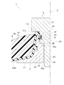
Embodiments of the present invention will be described in detail with reference to the drawings. As shown in FIG. 1, a
ライナー2は、図1及び図2に示すように、樹脂製であって内部が中空になっている。ライナー2の材料は特に制限されないが、収容する気体又は液体の種類や用途に応じて、例えば、ポリエチレン(PE)、高密度ポリエチレン(HDPE)、ポリアミド、ポリケトン、ポリフェニレンサルフィド(PPS)などが用いられる。ライナー2を樹脂で形成することで、軽量化を図ることができる。
As shown in FIGS. 1 and 2, the
ライナー2は、本実施形態では、液体又は気体を収容する収容部2aと、収容部2aに連続し中心軸C方向に沿って外側に突出する注排口部2bとで構成されている。収容部2aの形状は、特に制限されるものではなく、例えば、球形であってもよい。
In the present embodiment, the
注排口部2bは、図2に示すように、収容部2aに連続し円筒状を呈するネック部11と、折返し部12とで構成されている。
As shown in FIG. 2, the pouring / dispensing
ネック部11は、後記する基部22、中間部23及び埋設部24の外周面に当接している。ネック部11は、収容部2aから離間するにつれて中心軸C側に近接するように傾斜している。ネック部11の先端には、突部11aが形成されている。突部11aはネック部11の先端面において、周方向に亘って連続して形成されている。
The
折返し部12は、断面L字状を呈し、ネック部11の先端(端部)から収容部2a側に向けて延設されている。折返し部12は、後記する埋設部24の先端面及び内周面に当接している。
The folded
図2及び図3に示すように、口金3は、ライナー2の径方向内側に配設される金属製の部材である。口金3は、フランジ21と、基部22と、中間部23と、埋設部24とで主に構成されている。
As shown in FIGS. 2 and 3, the
フランジ21は、円環状を呈する。基部22は、円筒状を呈しフランジ21の内縁から立ち上がっている。基部22の内周面には雌ネジが形成されている。基部22の外周面には、周方向に沿って複数の凹溝26が形成されている。後にライナー2となる樹脂が凹溝26に入り込むことにより、注排口部2bに対する口金3の相対回転及び中心軸C方向の移動が規制される。
The
中間部23は、円筒状を呈し、基部22の先端面に形成されている。中間部23の厚さは、基部22の厚さよりも小さくなっている。中間部23の内径は、基部22の内径よりも大きくなっている。基部22と中間部23との段差部には、段差面25が形成されている。図3に示すように、中間部23の先端面には、径方向に沿う複数の凹溝27が形成されている(図3では一つのみ描画)。後にライナー2となる樹脂が凹溝27に入り込むことにより、注排口部2bに対する口金3の相対回転が規制される。なお、特許請求の範囲の「露出部」とは、基部22及び中間部23で構成される部位である。
The
埋設部24は、円筒状を呈し、中間部23の先端面に形成されている。埋設部24の厚さは、中間部23の厚さよりも小さくなっている。埋設部24の内径は、中間部23の内径よりも大きくなっている。図2に示すように、埋設部24の径方向外側、内側及び先端は、ネック部11及び折返し部12によって周方向に亘って連続して覆われている。
The embedded
補強層4は、FRP(繊維強化プラスチック)であり、ライナー2の外周を覆うように形成されている。補強層は、繊維強化樹脂に限定されるものではなく、ライナー2の強度を向上することができる他の材料で形成してもよい。
The reinforcing
バルブ5は、図2に示すように、ライナー2の注排口部2b及び口金3の内側に挿入されている。バルブ5は、本体部31と、中径部32と、小径部33とで構成されている。バルブ5は、特許請求の範囲の「取付部材」に相当する。「取付部材」は、注排口部2b及び口金3の少なくともいずれか一方に締結される部材であればよく、例えばジョイント部材であってもよい。
As shown in FIG. 2, the
本体部31の端面31aは、突部11aに当接している。中径部32の外径は、本体部31の外径よりも小さくなっている。中径部32の外径は、折返し部12の内径と略同等になっている。中径部32の外周面には、周方向に亘って凹部34が形成されている。凹部34は、第一シール部材6の取付座となる部位である。中径部32の端面32aは、段差面25に当接している。
The
小径部33の外径は、中径部32の外径より小さくなっている。小径部33の外周面には、基部22の雌ネジに螺合される雄ネジが形成されている。
The outer diameter of the
第一シール部材6は、Oリングであって、凹部34に配置されている。第一シール部材6は、注排口部2bとバルブ5との間をシールする部材である。第一シール部材6は、具体的には、折返し部12と中径部32とに当接している。第一シール部材6は、中心軸C方向において、折返し部12及び埋設部24と重なる位置に配置されている。本実施形態では、第一シール部材6の隣にバックアップリング35を設けている。
The
次に、本実施形態に係る圧力容器の製造方法について説明する。本実施形態に係る圧力容器は、ブロー成形によって製造される。圧力容器の製造方法では、配置工程と、パリソン供給工程と、型締め工程と、ブロー工程と、補強層成形工程と、部品取付工程とを行う。 Next, a method for manufacturing a pressure vessel according to this embodiment will be described. The pressure vessel according to this embodiment is manufactured by blow molding. In the pressure vessel manufacturing method, an arrangement process, a parison supplying process, a mold clamping process, a blowing process, a reinforcing layer forming process, and a component attaching process are performed.
まず、図4に示すように、ブロー成形で用いるブローピン41について説明する。ブローピン41は、外筒部42と、外筒部42に対して進入又は縮退する内筒部43とを備えている。外筒部42は、いずれも筒状を呈する大径部44と、中径部45と、小径部46とを備えている。中径部45の外径は、中間部23の内径と略同等になっている。また、小径部46の外径は、基部22の内径と略同等になっている。
First, as shown in FIG. 4, a
小径部46の先端には、径方向に貫通するボール配置孔47が形成されている。ボール配置孔47には、ボール48が配置されている。大径部44と中径部45とで形成される段差部には、第一段差面49が形成されている。また、中径部45と小径部46とで形成される段差部には、第二段差面50が形成されている。
A
配置工程では、図4に示すように、ブローピン41に口金3を配置する。具体的には、小径部46に口金3を挿入して、第二段差面50に口金3の段差面25を当接させる。
In the arranging step, the
パリソン供給工程では、ブローピン41の外側であり、かつ、成形型K,Kの間に筒状のパリソンを供給する。なお、図4では、説明の便宜上、片方の成形型及びパリソンの描画を省略している。
In the parison supply process, a cylindrical parison is supplied outside the
型締め工程では、図4に示すように、成形型Kの型締めを行う。型締めを行うことにより、成形型Kと、口金3と、第一段差面49と、中径部45とで囲まれたキャビティが形成される。このキャビティによってライナー2の注排口部2bが形成される。
In the mold clamping process, the mold K is clamped as shown in FIG. By performing the mold clamping, a cavity surrounded by the molding die K, the
また、型締め工程では、図5に示すように、外筒部42に対して内筒部43を進入させる。これにより、ボール配置孔47からボール48が移動し、ボール48が小径部46の外周面からわずかに突出する。突出したボール48は、基部22の面取り面22aに当接する。これにより、ブローピン41に対する口金3の軸方向の移動が規制される。
In the mold clamping process, as shown in FIG. 5, the
ブロー工程では、図5に示すように、ブローピン41に空気を供給して、パリソンPを成形型Kに転写させる。パリソンPは、溶融した樹脂であって、後にライナー2となる材料である。ブロー成形の際の空気の圧力によって、パリソンPが流動し、前記したキャビティにパリソンPが確実に充填される。
In the blowing process, air is supplied to the blow pins 41 to transfer the parison P to the mold K as shown in FIG. The parison P is a melted resin and is a material that will later become the
ブローが終了したら、ブローピン41を成形型Kの外部に縮退させて脱型する。これにより、ライナー2と口金3とが一体化された複合部材が形成される。
When the blow is completed, the
補強層成形工程では、例えば、フィラメントワインディング法により、ライナー2及び口金3の外周に補強層4を形成する。
In the reinforcing layer forming step, the reinforcing
部品取付工程では、バルブ5の凹部34に第一シール部材6及びバックアップリング35を配置するとともに、バルブ5を口金3に螺合する。以上の工程によって、圧力容器1が形成される。
In the component mounting step, the
以上説明した圧力容器1によれば、注排口部2bは樹脂製であって突出しているため経年劣化によりへたりやすいが、注排口部2bの端部の内部に、周方向に亘って口金3の埋設部24が埋設されるとともに、口金3の露出部(基部22、中間部23)が注排口部2bの内壁として形成される。これにより、注排口部2bが補強される。そして、第一シール部材6は、この補強された注排口部2bをシールする位置、つまり、中心軸C方向において、折返し部12及び埋設部24と重なる位置に設けられているため、注排口部2bとバルブ5との間を第一シール部材6によって確実かつ長期にわたりシールできる。また、注排口部2bの内部に埋設部24及び露出部を配設するだけでよいため簡易な構造とすることができる。
According to the
また、本実施形態による圧力容器の製造方法によれば、ブローピン41の第二段差面50に口金3を配置してブロー成形するだけでよいため、作業手間や製造コストを削減することができる。また、第二段差面50とボール48とで口金3を挟むように配置することで、ブロー成形時における口金3の浮き上がりを防止できる。これにより、成形作業を精度よく行うことができる。
Further, according to the method for manufacturing a pressure vessel according to the present embodiment, it is only necessary to place the
[変形例]
次に、図6を参照して、第一実施形態の変形例に係る圧力容器1Aについて説明する。図6に示すように、圧力容器1Aは、第一シール部材6に加えて第二シール部材7を備えている点で第一実施形態と相違する。当該変形例では、第二シール部材7周りの構成を除いては、第一実施形態と略同等であるため、重複する部分については同一の符号を付して説明を省略する。
[Modification]
Next, a pressure vessel 1A according to a modification of the first embodiment will be described with reference to FIG. As shown in FIG. 6, the
口金3の基部22のうち、基端側の内周面には雌ネジが形成されている。また、先端側の内周面は平坦面になっている。当該先端側の内周面の内径は、基端側の内径に比べて小さくなっている。
A female screw is formed on the inner peripheral surface of the base end side of the
バルブ5Aは、本体部31と、中径部32と、小径部33とで構成されている。小径部33の基端側の外周面には、雄ネジが形成されている。当該バルブ5Aの雄ネジと基部22の基端側に形成された雌ネジとが螺合する。小径部33の先端側には、凹部36が形成されている。凹部36は、第二シール部材7の取付座となる部位である。第二シール部材7の隣りには、バックアップリング35が設置されている。
The
当該変形例に係る圧力容器1Aによっても、第一実施形態に係る圧力容器1と同等の効果を得ることができる。また、圧力容器1Aの第二シール部材7によれば、口金3とバルブ5Aとの間をシールすることができる。圧力容器1Aでは、第一シール部材6に加えて、第二シール部材7を備えているため、シール性能をより向上させることができる。例えば、圧力容器1Aに水素を貯留する場合は、水素脆化によって口金とバルブとの係止部が脆くなり、ネジの締結力が低下するおそれがある。しかし、本実施形態によれば、バルブ5Aの先端側で水素の流通を阻止できるため、水素脆化を防止できる。
Even with the pressure vessel 1A according to the modification, it is possible to obtain the same effect as the
前記した実施形態及び変形例では、さらに、口金3の中間部23とバルブ5の中径部32との間にシール部材を設けてもよい。
In the above-described embodiment and modification, a seal member may be further provided between the
[第二実施形態]
次に、図7等を用いて本発明の第二実施形態に係る圧力容器1Bについて説明する。圧力容器1Bは、ライナー102と、口金103と、補強層104と、アタッチメント部材105と、バルブ106と、第一シール部材107と、第二シール部材108とで主に構成されている。
[Second Embodiment]
Next, a
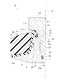
ライナー102は、収容部102aと、注排口部102bとで構成されている。ライナー102は、第一実施形態に係るライナー2と概ね同じ構成である。注排口部102bは、ネック部111と、折返し部112とで構成されている。
The liner 102 includes a housing portion 102a and a pouring / dispensing
注排口部102bは、図7に示すように、収容部102aに連続し円筒状を呈するネック部111と、ネック部111の先端から収容部102a側に折り返される折返し部112とで構成されている。
As shown in FIG. 7, the pouring / dispensing
ネック部111は、後記する基部122、中間部123及び埋設部124の外周面に当接している。折返し部112は、断面L字状を呈し、ネック部111の先端から収容部102a側に向けて延設されている。折返し部112は、後記する埋設部124の先端面及び内周面に当接している。
The
図7及び図8に示すように、口金103は、ライナー102の径方向内側に配設される金属製の部材である。口金103は、フランジ121と、基部122と、中間部123と、埋設部124とで主に構成されている。
As shown in FIGS. 7 and 8, the
フランジ121は、円環状を呈する。基部122は、円筒状を呈し、フランジ121の内縁から立ち上がっている。基部122の内周面には雌ネジが形成されている。基部122の外周面には、周方向に沿って複数の凹溝126(図8では一つのみ描画)が形成されている。また、フランジ121及び基部122には、外側に張り出す複数のリブ122aが形成されている。リブ122aは、周方向に等間隔で形成されている。後にライナー102となる樹脂が凹溝126及び隣り合うリブ122a,122aの間に入り込むことにより、注排口部102bに対する口金103の相対回転及び中心軸C方向の移動が規制される。
The
中間部123は、円筒状を呈し、基部122の先端に形成されている。中間部123の厚さは、基部122の厚さよりも小さくなっている。中間部123の内径は、基部122の内径よりも大きくなっている。基部122と中間部123との段差部には、段差面125が形成されている。段差面125には、径方向に沿う一対の凹溝127(図8では一つのみ描画)が形成されている。凹溝127には、後記するアタッチメント部材105の突起部132aが嵌合される。
The
図7に示すように、特許請求の範囲の「露出部」とは、基部122及び中間部123で構成される部位である。
As shown in FIG. 7 , the “exposed part” in the claims is a part constituted by a
埋設部124は、円筒状を呈し、中間部123の先端面に形成されている。埋設部124の厚さは、中間部123の厚さよりも小さくなっている。埋設部124の内径は、中間部123の内径よりも大きくなっている。図7に示すように、埋設部124の径方向外側、内側及び先端は、ネック部111及び折返し部112によって周方向に亘って連続して覆われている。
The embedded
補強層104は、FRP(繊維強化プラスチック)であり、ライナー102の外周を覆うように形成されている。補強層は、繊維強化樹脂に限定されるものではなく、ライナー102の強度を向上することができる他の材料で形成してもよい。
The reinforcing
図7及び図9に示すように、アタッチメント部材105は、注排口部102b及び口金103の先端(端部)に取り付けられる金属製部材である。アタッチメント部材105は、基部131と、内壁部132と、外壁部133とで構成されている。
As shown in FIGS. 7 and 9, the
基部131は、円環状を呈する。基部131の外縁には回転工具を当接させるための一対の切欠き面131aが形成されている。基部131の内縁には、周方向に亘って溝部131bが形成されている。溝部131bには、第一シール部材107が配設される。
The
内壁部132は、筒状を呈し、基部131の内縁から基部131に対して略垂直に延設されている。内壁部132の内径は、後記するバルブ106の小径部142の外径と略同等になっている。内壁部132の外径は、折返し部112の内径と略同等になっている。内壁部132の外周面には、周方向に亘って凹部135が形成されている。凹部135は、第二シール部材108の取付座となる部位である。また、図9に示すように、内壁部132の先端面には一対の突起部132aが形成されている。突起部132aは、凹溝127に嵌合する形状になっている。また、内壁部132の先端の外側には、面取り部132bが形成されている。面取り部132bを備えることで、注排口部102bに挿入しやすくなっている。
The
外壁部133は、円筒状を呈し、内壁部132よりも径方向外側において、基部131に対して略垂直に延設されている。外壁部133の高さは、内壁部132の高さよりも小さくなっている。図7に示すように、外壁部133の内径は、ネック部111の先端側の外径と略同等になっている。内壁部132と外壁部133との間に注排口部102bが嵌め合わされている。
The
図7に示すように、バルブ106は、アタッチメント部材105の内壁部132及び口金103の内側に挿入されている。バルブ106は、本体部141と、小径部142とで構成されている。本体部141の端面141aは、アタッチメント部材105の基部131に当接している。
As shown in FIG. 7, the
小径部142の外径は、本体部141の外径よりも小さくなっている。小径部142の基端側の外周面は、平坦になっている。小径部142の先端側の外周面には、基部122に螺合される雄ネジが形成されている。
The outer diameter of the
第一シール部材107は、Oリングであって、溝部131bに配置されている。第一シール部材107は、アタッチメント部材105とバルブ106との間をシールする部材である。第一シール部材107は、具体的には、基部131と端面141aとに当接している。
The
第二シール部材108は、Oリングであって、凹部135に配置されている。第二シール部材108は、注排口部102bとアタッチメント部材105との間をシールする部材である。第二シール部材108は、具体的には、折返し部112と内壁部132とに当接している。第二シール部材108は、中心軸C方向において、折返し部112及び埋設部124と重なる位置に配置されている。本実施形態では、第二シール部材108の隣にバックアップリング134を設けている。
The
次に、本実施形態に係る圧力容器の製造方法について説明する。本実施形態に係る圧力容器は、ブロー成形によって製造される。圧力容器の製造方法では、配置工程と、パリソン供給工程と、型締め工程と、ブロー工程と、アタッチメント取付工程と、補強層成形工程と、部品取付工程とを行う。配置工程からブロー工程までは第一実施形態と同等なので、詳細な説明は省略する。 Next, a method for manufacturing a pressure vessel according to this embodiment will be described. The pressure vessel according to this embodiment is manufactured by blow molding. In the pressure vessel manufacturing method, an arrangement process, a parison supply process, a mold clamping process, a blow process, an attachment mounting process, a reinforcing layer forming process, and a component mounting process are performed. Since the arrangement process to the blowing process are the same as those in the first embodiment, detailed description is omitted.
アタッチメント取付工程では、凹部135に第二シール部材108及びバックアップリング134を取り付けつつ、ライナー102と口金103とで形成された複合部材に対し、ライナー102の先端にアタッチメント部材105を取り付ける。具体的には、アタッチメント部材105の内壁部132と外壁部133の隙間に、注排口部102bの先端を嵌め合わせる。
In the attachment attaching step, the
補強層成形工程では、例えば、フィラメントワインディング法により、ライナー102及びアタッチメント部材105の外周に補強層104を形成する。
In the reinforcing layer forming step, the reinforcing
部品取付工程では、バルブ106の小径部142に第一シール部材107を取り付けるか若しくは溝部131bに第一シール部材107を配置する。そして、バルブ106をアタッチメント部材105に挿入しつつ、口金103に螺合する。以上の工程によって、圧力容器1Bが形成される。なお、圧力容器1Bの製造方法は、前記した方法に限定されるものではなく、例えば、補強層104を形成した後にアタッチメント部材105を取り付けてもよい。
In the component attaching step, the
以上説明した圧力容器1Bによれば、注排口部102bは樹脂製であって突出しているため経年劣化によりへたりやすいが、注排口部102bの端部の内部に、周方向に亘って口金103の埋設部124が埋設されるとともに、口金103の露出部(基部122、中間部123)が注排口部102bの内壁として形成される。これにより、注排口部102bが補強される。そして、第二シール部材108は、この補強された注排口部102bをシールする位置、つまり、中心軸C方向において、折返し部112及び埋設部124と重なる位置に設けられているため、注排口部102bとアタッチメント部材105との間を第二シール部材108によって確実かつ長期にわたりシールできる。また、注排口部102bの内側に埋設部124及び露出部を配設するだけでよいため簡易な構造とすることができる。
According to the
圧力容器1Bの口金103に取り付けられるバルブ106やジョイント部材等を含めた取付部材は、様々な形状及び大きさを備えている。したがって、取付部材の変更に伴って口金103の形状を変更しなければならず、さらには、成形型や製造工程も変更しなければならない場合がある。しかし、本実施形態のように、口金103の先端にアタッチメント部材105を設けることで、口金103の形状等は変更せずに様々なタイプの取付部材に対応することができる。
The attachment members including the
また、本実施形態では、第一シール部材107を設けているため、アタッチメント部材105とバルブ106との間をシールすることができる。
In the present embodiment, since the
[第一変形例]
次に、図10を参照して、第二実施形態の第一変形例に係る圧力容器1Cについて説明する。図10に示すように、圧力容器1Cは、第二シール部材108に加えて第三シール部材109を備えている点で第二実施形態と相違する。第一変形例では、第一シール部材107(図7参照)を省略している点、第三シール部材109を設けた点を除いては、第二実施形態と略同等であるため、重複する部分については同一の符号を付して説明を省略する。
[First modification]
Next, a
口金103の基部122のうち、基端側の内周面には雌ネジが形成されている。また、先端側の内周面は平坦になっている。当該先端側の内径は、基端側の内径に比べて小さくなっている。
A female screw is formed on the inner peripheral surface of the base end side of the
バルブ106Cは、本体部141Cと、小径部142Cとで構成されている。小径部142Cの外周面うち、先端側と基端側は平坦になっており、中央部分には雄ネジが形成されている。
The
バルブ106Cの先端の外周面には、周方向に亘って凹部136が形成されている。凹部136は、第三シール部材109が配置される部位である。第三シール部材109の隣りにはバックアップリング134が配置される。
A
第一変形例に係る圧力容器1Cによれば、第二実施形態に係る圧力容器1Bと略同等の効果を得ることができる。さらに、圧力容器1Cの第三シール部材109によれば、口金103とバルブ106Cとの間をシールすることができる。圧力容器1Cでは、第二シール部材108に加えて、第三シール部材109を備えているため、シール性能をより向上させることができる。例えば、圧力容器1Cに水素を貯留する場合は、水素脆化によって口金103とバルブ106Cとの係止部が脆くなり、ネジの締結力が低下するおそれがある。しかし、本実施形態によれば、バルブ106Cの先端側で水素の流通を阻止できるため、水素脆化を防止できる。なお、圧力容器1Cにおいて、第二実施形態で用いた第一シール部材107をさらに設けてもよい。
According to the
[第二変形例]
次に、図11を参照して、第二実施形態の第二変形例に係る圧力容器1Dについて説明する。図11に示すように、圧力容器1Dは、第二シール部材108及び第三シール部材109に加えて、第四シール部材110を備えている点で第一変形例に係る圧力容器1Cと相違する。圧力容器1Dは、第四シール部材110を設けた点を除いては、第一変形例に係る圧力容器1Cと略同等であるため、重複する部分については同一の符号を付して説明を省略する。
[Second modification]
Next, a
アタッチメント部材105Dは、基部131Dと、内壁部132Dと、外壁部133Dとで構成されている。内壁部132Dの外周面には、基端側に第一凹部137が形成されており、先端側に第二凹部138が形成されている。第一凹部137には、第二シール部材108とバックアップリング134が配置されている。第二凹部138には、第四シール部材110が配置されている。第四シール部材110は、中間部123と内壁部132Dとの間をシールする部材である。
The
第二変形例に係る圧力容器1Dによれば、第一変形例と略同等の効果を得ることができる。また、例えば、圧力容器1Dに水素を貯留する場合においては、第四シール部材110を設けているため、ライナー102と口金103との間を流通する水素がネジ側に流通するのを阻止できる。これにより、さらにネジ部の水素脆化を防止できる。
According to the
[第三変形例]
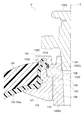
次に、図12を参照して、第二実施形態に係る第三変形例に係る圧力容器1Eについて説明する。図12に示すように、圧力容器1Eは、アタッチメント部材105E及びバルブ106Eの形状が第二実施形態と相違する。
[Third modification]
Next, with reference to FIG. 12, the
アタッチメント部材105Eは、基部131Eと、内壁部132Eと、外壁部133Eとで構成されている。
The
内壁部132Eは、大径部132Eaと、小径部132Ebとで構成されている。大径部132Eaは、基部131Eに対して垂直に延設されており、円筒状を呈する。大径部132Eaの内周面には雌のテーパーネジが形成されている。大径部132Eaの外周面は、平坦になっている。大径部132Eaの外周面には、周方向に亘って凹部139が形成されている。凹部139には、第二シール部材108及びバックアップリング134が取り付けられている。小径部132Ebの外周面には、基部122の雌ネジに螺合する雄ネジが形成されている。
The
第三変形例に係る圧力容器1Eによれば、第二実施形態に係る圧力容器1Bと略同等の効果を得ることができる。また、圧力容器1Eのアタッチメント部材105Eの内径は、第二実施形態に係るアタッチメント部材105の内径に比べて小さくなっている。バルブ106Eのように、螺合される部位の外径が小さい場合等は、アタッチメント部材105Eを用いることで、対応することができる。第三変形例では汎用バルブを例示しており、アタッチメント部材105Eとバルブ106Eとのシールは、バルブ106E側のテーパーネジ部にシールテープを巻いてシールしている。
According to the
以上本発明の実施形態及び変形例について説明したが、本発明の趣旨に反しない範囲において適宜設計変更が可能である。例えば、基部とバルブとが螺合される部位や、アタッチメント部材とバルブとが螺合される部位に、前記した第三変形例と同様にシールテープを設けてシールしてもよい。また、本実施形態ではバルブと口金又はアタッチメント部材とをネジで締結するようにしたが、他の構成で締結してもよい。 Although the embodiments and modifications of the present invention have been described above, design changes can be made as appropriate without departing from the spirit of the present invention. For example, a seal tape may be provided and sealed at a site where the base and the valve are screwed together or at a site where the attachment member and the valve are screwed, similarly to the third modification described above. In the present embodiment, the valve and the base or attachment member are fastened with screws, but may be fastened with other configurations.
1 圧力容器
2 ライナー
2a 収容部
2b 注排口部
3 口金
4 補強層
5 バルブ(取付部材)
6 第一シール部材(シール部材)
7 第二シール部材(シール部材)
11 ネック部
12 折返し部
21 フランジ
22 基部
23 中間部
24 埋設部
102 ライナー
102a 収容部
102b 注排口部
103 口金
104 補強層
105 アタッチメント部材
106 バルブ(取付部材)
107 第一シール部材(シール部材)
108 第二シール部材(シール部材)
109 第三シール部材(シール部材)
110 第四シール部材(シール部材)
K 成形型
P パリソン
DESCRIPTION OF
6 First seal member (seal member)
7 Second seal member (seal member)
DESCRIPTION OF
107 First seal member (seal member)
108 Second seal member (seal member)
109 Third seal member (seal member)
110 Fourth seal member (seal member)
K Mold P P Parison
Claims (4)
前記注排口部が端部において径方向外側から内側に折り返されることで周方向に亘って埋設される埋設部、前記埋設部から連続して形成され前記注排口部の内壁として露出する露出部及び前記露出部に連続し前記ライナーに沿って延設されたフランジを備える口金と、
前記口金の前記埋設部が埋設された前記注排口部の端部の径方向内側及び径方向外側を覆い周方向に亘って嵌め合わされるアタッチメント部材と、
前記アタッチメント部材及び前記露出部の少なくともいずれかの径方向内側に取り付けられる取付部材と、
前記注排口部と前記アタッチメント部材との間をシールするシール部材と、
前記ライナーの外側に設けられる補強層と、を有し、
前記補強層は、前記ライナーの注排口部においては、前記ライナーが外部に露出しないように前記ライナー及び前記アタッチメント部材の外側に設けられていることを特徴とする圧力容器。 An integrally formed resin liner provided with a storage part for storing liquid or gas and a cylindrical pouring port part protruding from the storage part;
Exposure the watch discharge port portion is exposed as the inner wall diameter buried portion is buried from the outwardly over a circumferential direction by being folded inward, is formed continuously from the embedded portion the watch discharge port portion at the end A base comprising a flange that is continuous with the portion and the exposed portion and extends along the liner ;
An attachment member that covers the radially inner side and the radially outer side of the end portion of the pouring port portion in which the buried portion of the base is buried, and is fitted over the circumferential direction;
An attachment member attached to a radially inner side of at least one of the attachment member and the exposed portion;
A sealing member that seals between the pouring port and the attachment member;
A reinforcing layer provided on the outside of the liner,
The pressure vessel according to claim 1, wherein the reinforcing layer is provided outside the liner and the attachment member so that the liner is not exposed to the outside in the pouring port portion of the liner.
Priority Applications (4)
| Application Number | Priority Date | Filing Date | Title |
|---|---|---|---|
| JP2013119749A JP6235797B2 (en) | 2013-06-06 | 2013-06-06 | Pressure vessel |
| US14/895,265 US20160123538A1 (en) | 2013-06-06 | 2014-05-07 | Pressure container |
| CN201480032244.6A CN105264278B (en) | 2013-06-06 | 2014-05-07 | Pressure vessel |
| PCT/JP2014/062278 WO2014196304A1 (en) | 2013-06-06 | 2014-05-07 | Pressure container |
Applications Claiming Priority (1)
| Application Number | Priority Date | Filing Date | Title |
|---|---|---|---|
| JP2013119749A JP6235797B2 (en) | 2013-06-06 | 2013-06-06 | Pressure vessel |
Publications (3)
| Publication Number | Publication Date |
|---|---|
| JP2014238110A JP2014238110A (en) | 2014-12-18 |
| JP2014238110A5 JP2014238110A5 (en) | 2016-06-16 |
| JP6235797B2 true JP6235797B2 (en) | 2017-11-22 |
Family
ID=52007957
Family Applications (1)
| Application Number | Title | Priority Date | Filing Date |
|---|---|---|---|
| JP2013119749A Active JP6235797B2 (en) | 2013-06-06 | 2013-06-06 | Pressure vessel |
Country Status (4)
| Country | Link |
|---|---|
| US (1) | US20160123538A1 (en) |
| JP (1) | JP6235797B2 (en) |
| CN (1) | CN105264278B (en) |
| WO (1) | WO2014196304A1 (en) |
Cited By (3)
| Publication number | Priority date | Publication date | Assignee | Title |
|---|---|---|---|---|
| KR20220090658A (en) * | 2020-12-22 | 2022-06-30 | 주식회사 동희산업 | High pressure vessel for vehicle |
| KR102432508B1 (en) * | 2022-01-26 | 2022-08-17 | 신병천 | High-pressure gas storage tank with multiple pressurized nozzle boss |
| KR102432512B1 (en) * | 2022-01-26 | 2022-08-17 | 신병천 | High-pressure gas storage tank with multiple pressurized nozzle boss |
Families Citing this family (14)
| Publication number | Priority date | Publication date | Assignee | Title |
|---|---|---|---|---|
| KR102429160B1 (en) * | 2016-03-23 | 2022-08-03 | 현대자동차주식회사 | Self tighten sealing end plug |
| EP3366975B1 (en) * | 2017-02-23 | 2021-12-29 | Nproxx B.V. | Pole cap with pressure connection element for pressure vessels |
| PL242453B1 (en) * | 2017-03-03 | 2023-02-27 | Worthington Ind Inc | Connector pipe assembly for a composite cylinder |
| JP6881147B2 (en) * | 2017-08-10 | 2021-06-02 | トヨタ自動車株式会社 | High-pressure container and fuselage reinforcement layer wrapping method |
| CN107339599A (en) * | 2017-08-11 | 2017-11-10 | 天津安易达复合气瓶有限公司 | A kind of nonmetallic inner bag winds composite cylinder and its manufacture method entirely |
| US10753474B2 (en) * | 2017-11-07 | 2020-08-25 | Hexagon Technology As | Blind boss fitting with redundant seal |
| CN208546740U (en) * | 2017-12-31 | 2019-02-26 | 亚普汽车部件股份有限公司 | A kind of sealing device of high-pressure composite containers plastic inner container |
| CN108131556B (en) * | 2017-12-31 | 2023-06-30 | 亚普汽车部件股份有限公司 | High-pressure composite container with sealing structure |
| JP6674490B2 (en) * | 2018-02-21 | 2020-04-01 | 本田技研工業株式会社 | High pressure tank |
| JP6988657B2 (en) * | 2018-04-06 | 2022-01-05 | トヨタ自動車株式会社 | High pressure tank |
| EP3587895B1 (en) * | 2018-06-22 | 2020-10-07 | Nproxx B.V. | Self-sealing valve connection for pressure vessel |
| JP6941648B2 (en) * | 2019-08-23 | 2021-09-29 | 本田技研工業株式会社 | High pressure tank |
| FR3116322B1 (en) * | 2020-11-13 | 2023-06-16 | Faurecia Systemes Dechappement | Pressurized gas tank |
| FR3133424A1 (en) * | 2022-03-08 | 2023-09-15 | Faurecia Systemes D'echappement | Casing for a pressurized gas tank |
Family Cites Families (16)
| Publication number | Priority date | Publication date | Assignee | Title |
|---|---|---|---|---|
| GB8329905D0 (en) * | 1983-11-09 | 1983-12-14 | British Petroleum Co Plc | Container |
| JP3453905B2 (en) * | 1995-02-15 | 2003-10-06 | 東レ株式会社 | Gas cylinder |
| JPH1113994A (en) * | 1997-06-30 | 1999-01-22 | Arisawa Mfg Co Ltd | Manufacture of frp pressure vessel |
| JP2000266288A (en) * | 1999-03-11 | 2000-09-26 | Mitsubishi Chemicals Corp | Pressure vessel and its manufacture |
| JP2001173893A (en) * | 1999-12-21 | 2001-06-29 | Mitsubishi Chemicals Corp | Pressure container |
| JP2002005397A (en) * | 2000-06-20 | 2002-01-09 | Mitsubishi Chemicals Corp | Pressure container |
| JP2005265138A (en) * | 2004-03-22 | 2005-09-29 | Toray Ind Inc | Pressure vessel |
| JP4935117B2 (en) * | 2005-11-08 | 2012-05-23 | トヨタ自動車株式会社 | tank |
| ITBS20070058A1 (en) * | 2007-04-16 | 2008-10-17 | Hydro System Treat S R L | TANK WITH FLANGE |
| JP4599380B2 (en) * | 2007-09-04 | 2010-12-15 | 八千代工業株式会社 | Seal structure of high pressure vessel |
| JP5179458B2 (en) * | 2009-11-11 | 2013-04-10 | 八千代工業株式会社 | Pressure vessel seal structure |
| WO2011152732A1 (en) * | 2010-05-31 | 2011-12-08 | Ragasco As | Inlet/outlet system for composite pressure container |
| EP2783151B1 (en) * | 2011-06-28 | 2021-03-31 | Hexagon Ragasco AS | Improved boss for composite pressure container |
| JP5581295B2 (en) * | 2011-07-13 | 2014-08-27 | 八千代工業株式会社 | Pressure vessel |
| JP5902028B2 (en) * | 2011-11-29 | 2016-04-13 | 八千代工業株式会社 | Manufacturing method of pressure vessel |
| US20140272670A1 (en) * | 2013-03-15 | 2014-09-18 | GM Global Technology Operations LLC | Method and apparatus for making a fuel storage tank with a liner and inner bag for a fuel storage system |
-
2013
- 2013-06-06 JP JP2013119749A patent/JP6235797B2/en active Active
-
2014
- 2014-05-07 US US14/895,265 patent/US20160123538A1/en not_active Abandoned
- 2014-05-07 WO PCT/JP2014/062278 patent/WO2014196304A1/en active Application Filing
- 2014-05-07 CN CN201480032244.6A patent/CN105264278B/en active Active
Cited By (4)
| Publication number | Priority date | Publication date | Assignee | Title |
|---|---|---|---|---|
| KR20220090658A (en) * | 2020-12-22 | 2022-06-30 | 주식회사 동희산업 | High pressure vessel for vehicle |
| KR102453127B1 (en) | 2020-12-22 | 2022-10-12 | 주식회사 동희산업 | High pressure vessel for vehicle |
| KR102432508B1 (en) * | 2022-01-26 | 2022-08-17 | 신병천 | High-pressure gas storage tank with multiple pressurized nozzle boss |
| KR102432512B1 (en) * | 2022-01-26 | 2022-08-17 | 신병천 | High-pressure gas storage tank with multiple pressurized nozzle boss |
Also Published As
| Publication number | Publication date |
|---|---|
| CN105264278A (en) | 2016-01-20 |
| WO2014196304A1 (en) | 2014-12-11 |
| JP2014238110A (en) | 2014-12-18 |
| CN105264278B (en) | 2017-06-09 |
| US20160123538A1 (en) | 2016-05-05 |
Similar Documents
| Publication | Publication Date | Title |
|---|---|---|
| JP6235797B2 (en) | Pressure vessel | |
| JP5902028B2 (en) | Manufacturing method of pressure vessel | |
| JP5581295B2 (en) | Pressure vessel | |
| JP5985522B2 (en) | Pressure vessel | |
| JP7027439B2 (en) | Pole cap with pressure port element for pressure vessel | |
| CN106838602B (en) | Metal bottle mouth structure and LPG gas cylinder | |
| US9316357B2 (en) | Pressure vessel | |
| EP2322841A2 (en) | Pressure vessel having improved sealing arrangement | |
| EP3306146B1 (en) | Water tank for aircraft | |
| WO2012121059A1 (en) | Port structure for pressure container and method for manufacturing pressure container | |
| US20140272670A1 (en) | Method and apparatus for making a fuel storage tank with a liner and inner bag for a fuel storage system | |
| JP6236190B2 (en) | Pressure vessel | |
| US9630490B2 (en) | Filler pipe mounting structure | |
| JP6617034B2 (en) | Pressure vessel | |
| JP3218918U (en) | Base for gas container, and gas container with base | |
| US20190119032A1 (en) | Spray can | |
| JP2017129155A (en) | Pressure container | |
| US11852298B2 (en) | High-pressure gas tank and method for manufacturing high-pressure gas tank | |
| JP2018013176A (en) | Manufacturing method of tank | |
| JP6678460B2 (en) | Pressure vessel | |
| JP6287872B2 (en) | tank | |
| KR20230040242A (en) | High pressure storage tank and method for manufacturing the same | |
| KR20230040243A (en) | High pressure storage tank and method for manufacturing the same | |
| JP2016160981A (en) | Pressure container |
Legal Events
| Date | Code | Title | Description |
|---|---|---|---|
| A621 | Written request for application examination |
Free format text: JAPANESE INTERMEDIATE CODE: A621 Effective date: 20160415 |
|
| A521 | Request for written amendment filed |
Free format text: JAPANESE INTERMEDIATE CODE: A523 Effective date: 20160426 |
|
| RD02 | Notification of acceptance of power of attorney |
Free format text: JAPANESE INTERMEDIATE CODE: A7422 Effective date: 20160516 |
|
| A131 | Notification of reasons for refusal |
Free format text: JAPANESE INTERMEDIATE CODE: A131 Effective date: 20170509 |
|
| A521 | Request for written amendment filed |
Free format text: JAPANESE INTERMEDIATE CODE: A523 Effective date: 20170621 |
|
| TRDD | Decision of grant or rejection written | ||
| A01 | Written decision to grant a patent or to grant a registration (utility model) |
Free format text: JAPANESE INTERMEDIATE CODE: A01 Effective date: 20171024 |
|
| A61 | First payment of annual fees (during grant procedure) |
Free format text: JAPANESE INTERMEDIATE CODE: A61 Effective date: 20171027 |
|
| R150 | Certificate of patent or registration of utility model |
Ref document number: 6235797 Country of ref document: JP Free format text: JAPANESE INTERMEDIATE CODE: R150 |
|
| R250 | Receipt of annual fees |
Free format text: JAPANESE INTERMEDIATE CODE: R250 |
|
| R250 | Receipt of annual fees |
Free format text: JAPANESE INTERMEDIATE CODE: R250 |
|
| R250 | Receipt of annual fees |
Free format text: JAPANESE INTERMEDIATE CODE: R250 |
|
| R250 | Receipt of annual fees |
Free format text: JAPANESE INTERMEDIATE CODE: R250 |