EP2000731A1 - Obturateur et procédé pour obturer des perçages d'une façon étanche - Google Patents
Obturateur et procédé pour obturer des perçages d'une façon étanche Download PDFInfo
- Publication number
- EP2000731A1 EP2000731A1 EP08401002A EP08401002A EP2000731A1 EP 2000731 A1 EP2000731 A1 EP 2000731A1 EP 08401002 A EP08401002 A EP 08401002A EP 08401002 A EP08401002 A EP 08401002A EP 2000731 A1 EP2000731 A1 EP 2000731A1
- Authority
- EP
- European Patent Office
- Prior art keywords
- closure
- workpiece
- bore
- wall
- collar
- Prior art date
- Legal status (The legal status is an assumption and is not a legal conclusion. Google has not performed a legal analysis and makes no representation as to the accuracy of the status listed.)
- Withdrawn
Links
- 238000000034 method Methods 0.000 title claims abstract description 26
- 239000000463 material Substances 0.000 claims description 20
- 238000007789 sealing Methods 0.000 claims description 7
- 230000000149 penetrating effect Effects 0.000 claims description 6
- 238000003825 pressing Methods 0.000 claims description 5
- 238000003780 insertion Methods 0.000 claims description 3
- 230000037431 insertion Effects 0.000 claims description 3
- 238000003892 spreading Methods 0.000 claims description 3
- 230000001154 acute effect Effects 0.000 claims description 2
- 238000010079 rubber tapping Methods 0.000 claims 1
- 239000011800 void material Substances 0.000 abstract 1
- 230000035515 penetration Effects 0.000 description 3
- 150000001875 compounds Chemical class 0.000 description 2
- 229910000831 Steel Inorganic materials 0.000 description 1
- 206010053648 Vascular occlusion Diseases 0.000 description 1
- 230000015572 biosynthetic process Effects 0.000 description 1
- 238000010276 construction Methods 0.000 description 1
- 230000001419 dependent effect Effects 0.000 description 1
- 238000005553 drilling Methods 0.000 description 1
- 238000002347 injection Methods 0.000 description 1
- 239000007924 injection Substances 0.000 description 1
- JEIPFZHSYJVQDO-UHFFFAOYSA-N iron(III) oxide Inorganic materials O=[Fe]O[Fe]=O JEIPFZHSYJVQDO-UHFFFAOYSA-N 0.000 description 1
- 230000014759 maintenance of location Effects 0.000 description 1
- 238000004519 manufacturing process Methods 0.000 description 1
- 238000011089 mechanical engineering Methods 0.000 description 1
- 239000002184 metal Substances 0.000 description 1
- 239000000203 mixture Substances 0.000 description 1
- 238000010422 painting Methods 0.000 description 1
- 230000002093 peripheral effect Effects 0.000 description 1
- 238000003908 quality control method Methods 0.000 description 1
- 230000000284 resting effect Effects 0.000 description 1
- 239000003566 sealing material Substances 0.000 description 1
- 238000000926 separation method Methods 0.000 description 1
- 239000010959 steel Substances 0.000 description 1
- 238000003860 storage Methods 0.000 description 1
- 230000007704 transition Effects 0.000 description 1
Images
Classifications
-
- F—MECHANICAL ENGINEERING; LIGHTING; HEATING; WEAPONS; BLASTING
- F16—ENGINEERING ELEMENTS AND UNITS; GENERAL MEASURES FOR PRODUCING AND MAINTAINING EFFECTIVE FUNCTIONING OF MACHINES OR INSTALLATIONS; THERMAL INSULATION IN GENERAL
- F16L—PIPES; JOINTS OR FITTINGS FOR PIPES; SUPPORTS FOR PIPES, CABLES OR PROTECTIVE TUBING; MEANS FOR THERMAL INSULATION IN GENERAL
- F16L55/00—Devices or appurtenances for use in, or in connection with, pipes or pipe systems
- F16L55/10—Means for stopping flow in pipes or hoses
- F16L55/12—Means for stopping flow in pipes or hoses by introducing into the pipe a member expandable in situ
- F16L55/128—Means for stopping flow in pipes or hoses by introducing into the pipe a member expandable in situ introduced axially into the pipe or hose
- F16L55/13—Means for stopping flow in pipes or hoses by introducing into the pipe a member expandable in situ introduced axially into the pipe or hose the closure device being a plug fixed by plastic deformation
Definitions
- the invention relates to a closure, which has a cup shape with a closure bottom, a closure wall and a closure opening, which form a clear closure interior, with a loading side, which is described by the outside of the closure bottom, a closure side, located on the side of the closure opening, opposite to the load side, an expansion valve located on the inside of the clearing chamber whose outer diameter is slightly larger than the inner diameter of the closure interior and is arranged on the closure side penetrating into the clear closure interior, this for the plastic radial expansion of the closure wall in the clear closure interior in the direction of the load side is pressed for tight positive closure of a hole made in a surface of a workpiece bore and a collar on the closure side of the closure with a bottom, to Belas directed side, and an upper side, directed towards the closure side, wherein the underside of the collar after insertion of the closure in the workpiece located bore on a bore boundary, which adjoins the adjoining the bore surface of the workpiece, the full surface rests.
- the invention relates to a method for sealing holes in a workpiece with a closure with the steps of performing the bore to be created in the workpiece with a workpiece-specific drill, inserting the cup-shaped closure in the tightly closed bore, the collar of the closure of the Keep the closure from penetrating too deeply and store the closure and aligned by the collar of the closure over the entire surface of the edge of the bore rests, pressing the expansion of the closure of the closure side in the direction of the loading side in the closure interior, whereby the outer surface of the closure wall by plastic radial spreading of the closure interior by the expansion device to the wall of the bore is formed sealing.
- closures and methods for sealing closures of holes have long been known.
- a bore is pressed by means of the claimed, usually made of a metal, such as steel, closures by introducing an expansion element in the closure interior sealingly against the inner wall of the bore, whereby the bore is closed.
- the construction and use of such a plug for closing wells are very simple and therefore enjoys a very high penetration within the industrial sector of mechanical engineering.
- a method for sealing a hole is described.
- the arrangement is stepped bores in which a first bore is made in the workpiece to perform the function within the workpiece, for example, the internal connection of two pressure ducts within a metallic hydraulic block and a second bore coaxial with the first Bore and stepped from the first bore radially offset to the outside, which serves to store the closure on the bottom of the closure, in order to avoid too deep collapse into the bore.
- This type of tight closure of a bore by means of a closure is very complicated with the previously available on the market and known closures, as must be drilled in two different processes with two different drills in the workpiece.
- WO 00/37844 a device for sealingly closing pressurized medium thin-walled cavities by means of a closure assembly consisting of a closure sleeve, a guided in this closure sleeve pull pin with a shaft and a head, the head first expands the closure sleeve later on the pressurized side and then seals and a predetermined breaking point is provided for later separation of the shaft.
- the present invention has for its object to operate a further development of a closure and a method for tightly closing holes, on the one hand can be dispensed with process-intensive and complex stepped holes and on the other hand, a flush closure of the closure with the workpiece surface.
- the starting at the surface bore has a chamfer on the surface of the workpiece with a tip angle and an outer diameter
- the underside of the collar of the closure has a truncated cone surface with the same tip angle and outer diameter of the chamfer and the height of the collar of the closure exactly Depth of the chamfer
- a flat surface of the workpiece can be created by the collar of the closure rests positively in the chamfer of the bore boundary and the upper edge of the collar flush with the surface of the workpiece or springs back.
- the shutter is coaxially mounted in the bore and aligned coaxially in the bore to press the closure there precisely aligned, of course, the storage is more accurate than a flat bottom of the collar, there with a larger tolerance of the diameter of the bore Closure is nevertheless aligned coaxially.
- the collar which is dimensioned size-dependent, thereby forms an abutment for the closure used in the bore during the plastic deformation process by the expansion element, which is introduced into the closure interior.
- a pilot hole is made with a drill bit in the surface of the workpiece, wherein the pilot hole, which is carried out by means of a suitable drill, deeper than necessary for a pilot hole, but only so deep that a chamfered bore boundary with a sufficient depth at the outer edge of the Chamfer corresponding to the height of the collar of the closure, which is to be used in the further process, is formed so that the closure on the closure side flush with the surface of the workpiece, is performed.
- a flat surface is maintained despite inserted closure on the workpiece, can be attached to the other attachments, which should later rest flat on the surface of the workpiece.
- the material of the closure wall has an equal or greater hardness than the material of the workpiece, since this can ensure that the closure or the closure wall, which is plastically deformed radially outwardly by the expansion element, penetrates into the material of the workpiece and so on material-resistant, not self-releasing compound enters, which prevents the closure from wandering.
- the material of the expansion element is selected such that it is harder than the material of the closure wall, so that the expansion element does not plastically deform during the press-fitting process, but rather the closure wall.
- expansion element is spherical, it can be particularly well pressed into the interior of the closure.
- the expansion member can be frusto-conical or slightly conical cylindrical form, whereby a different plastic deformation area can be achieved within the closure.
- these circumferential annular grooves may be forced radially into the workpiece during the plastic deformation process.
- This material compound in which a mixture of materials is made in layers, alternately the material of the circumferential annular grooves and the material of the workpiece, prevents the closing of the closure at higher pressures, especially in pulsating pressure curves, which are present on the loading side.
- the annular peripheral grooves on the outer surface of the closure wall dig into the wall of the bore.
- the annular circumferential grooves on the outer surface of the closure wall in cross-section serrated and / or tooth-shaped.
- the side of the grooves respectively located on the loading side of the shutter is formed perpendicular to the outer surface of the shutter wall, and the side of the grooves respectively located on the shutter side of the shutter is obliquely formed at an acute angle ⁇ to the outer surface of the shutter wall.
- the material of the expansion element, as well as the closure itself, can not be made rust-resistant, so that a re-painting of an already painted workpiece can be avoided. Especially with hydraulic blocks, some of which have already been pre-painted for production, repainting would no longer be necessary, or is often undesirable.
- the expansion element In order to exert a constant force on the expansion element during the entire injection process, the expansion element is pressed with a hydraulic tool. As a result, excessive or too low forces are prevented during the pressing-in process of the expansion element.
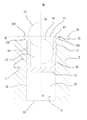
- the 1 shows a closure 1 in a bore 3, which is arranged in a workpiece 2, for example a hydraulic block, with a surface 21, preferably orthogonal to the surface 21, from a closure side B in the direction of a loading side A.
- the bore 3 has a Mouth 34, a wall 32 and a bottom 33 which define a bore interior 35.
- the closure 1 has a closure wall 10, a closure opening 11 and a closure bottom 12, which span and bound a closure interior 13.
- an expansion element 14 is arranged from the closure side B forth, which is inserted into the closure interior 13 penetrating for later pressing in the direction of the loading side A.
- annular circumferential grooves 17 are provided on the outer surface on the outer surface and in the region of the closure opening 11, a collar 15 with a bottom 151, a top 152 and a height H is arranged.
- the collar 15 is flush with its bottom 151 on a bore boundary 31, which represents the edge region of the bore 3 around the mouth 34.
- the bore boundary 31 has a chamfer 311.
- the attention is particularly directed to the bottom 151 of the collar 15 of the closure 1 and the chamfer 311 of the bore 31.
- the underside 151 of the collar 15 has a truncated cone lateral surface with an identical point angle and outer diameter of the chamfer 311 of the bore boundary 31. It is important that the point angle and the outer diameter of the chamfer 311 are almost identical to the tip angle and the outer diameter of the truncated cone surface of the bottom 151 of the collar 15, whereby a positive and full-surface placement of the bottom 151 of the collar 15 in the surface 21 of the workpiece 2 in the area of the bore boundary 31 is ensured.
- the collar also has a height H corresponding to the depth of the chamfered boundary 311.
- the collar 15 thus limits the penetration depth of the closure 1 within the bore, stores it, and directs the closure 1 in the to be closed Bore 3 coaxial. Furthermore, the collar 15 serves as an abutment for the forces occurring during the press-fitting process, which act on the closure 1 from the closure side B on the expansion element 14. The closure 1 sits snugly in the hole. 3
- the transition between the plastically deformed closure wall 10 and the wall 32 of the bore 3 forms the sealing region of the closure 1.
- a flush termination between the upper side 152 of the collar 15 of the closure 1 with the surface 21 of the workpiece 2 is obtained, so that any attachment parts which are to be arranged in the region of the closure can likewise be applied flush to the surface 21 of the workpiece 2 ,
- the expansion member 14 is shown in the state prior to the pressing of the expansion member 14.
- the closure wall 10 is plastically deformed with the arranged on the outside annular circumferential grooves 17.
- the expansion member 14 penetrates into the closure interior 13 of the closure 1 through the closure opening 11, in which the expansion element is held, a.
- a force is exerted on the expansion member 14 of the closure side B, whereby the expansion member 14 in the Closure interior 13 is pressed in the direction of the loading side A.
- the expansion member 14 presses the closure wall 10 with the annular circumferential grooves located on the outside in the wall 32 of the bore 3, whereby a permanent, non-detachable material connection is formed. Nevertheless, annular circumferential grooves for a sealing material connection are not mandatory.
Landscapes
- Engineering & Computer Science (AREA)
- General Engineering & Computer Science (AREA)
- Mechanical Engineering (AREA)
- Automatic Assembly (AREA)
- Pressure Vessels And Lids Thereof (AREA)
Applications Claiming Priority (1)
| Application Number | Priority Date | Filing Date | Title |
|---|---|---|---|
| DE102007027004A DE102007027004A1 (de) | 2007-06-07 | 2007-06-07 | Verschluss und Verfahren zum dichten Verschließen von Bohrungen |
Publications (1)
| Publication Number | Publication Date |
|---|---|
| EP2000731A1 true EP2000731A1 (fr) | 2008-12-10 |
Family
ID=39768582
Family Applications (1)
| Application Number | Title | Priority Date | Filing Date |
|---|---|---|---|
| EP08401002A Withdrawn EP2000731A1 (fr) | 2007-06-07 | 2008-06-06 | Obturateur et procédé pour obturer des perçages d'une façon étanche |
Country Status (2)
| Country | Link |
|---|---|
| EP (1) | EP2000731A1 (fr) |
| DE (1) | DE102007027004A1 (fr) |
Cited By (1)
| Publication number | Priority date | Publication date | Assignee | Title |
|---|---|---|---|---|
| EP2613061A3 (fr) * | 2012-01-09 | 2015-03-04 | Scanwill ApS | Dispositif de verrouillage d'un forage hydraulique et/ou pneumatique |
Citations (6)
| Publication number | Priority date | Publication date | Assignee | Title |
|---|---|---|---|---|
| CH508828A (de) * | 1970-07-08 | 1971-06-15 | Hirmann Georg | Verfahren zum Verschliessen von Bohrungen in Werkstücken und Stopfen zur Ausführung des Verfahrens |
| GB1236338A (en) * | 1968-05-20 | 1971-06-23 | Lee Co | Expandable sealing plug assembly |
| EP0364699A2 (fr) * | 1988-09-16 | 1990-04-25 | Koenig Verbindungstechnik Ag | Méthode pour obturer de façon étanche un orifice, et orifice obturé |
| US5779085A (en) * | 1997-03-11 | 1998-07-14 | Gas Research Institute | Expandable pin plug for automated use |
| WO2000037844A1 (fr) * | 1998-12-22 | 2000-06-29 | Umformtechnik Und Kraftfahrzeugkomponenten Meissen Gmbh | Dispositif destine a la fermeture hermetique de compartiments creux a minces parois alimentes en agent de pression |
| DE10220620A1 (de) * | 2002-05-08 | 2003-11-27 | Siemens Ag | Verschlussvorrichtung und Verfahren zum dichten Verschließen von Bohrungen |
Family Cites Families (2)
| Publication number | Priority date | Publication date | Assignee | Title |
|---|---|---|---|---|
| US3525453A (en) | 1968-11-07 | 1970-08-25 | Lee Co | Sealing plug assembly |
| US4436117A (en) | 1982-12-02 | 1984-03-13 | Martin John E | Leak resistant plug assembly |
-
2007
- 2007-06-07 DE DE102007027004A patent/DE102007027004A1/de not_active Withdrawn
-
2008
- 2008-06-06 EP EP08401002A patent/EP2000731A1/fr not_active Withdrawn
Patent Citations (6)
| Publication number | Priority date | Publication date | Assignee | Title |
|---|---|---|---|---|
| GB1236338A (en) * | 1968-05-20 | 1971-06-23 | Lee Co | Expandable sealing plug assembly |
| CH508828A (de) * | 1970-07-08 | 1971-06-15 | Hirmann Georg | Verfahren zum Verschliessen von Bohrungen in Werkstücken und Stopfen zur Ausführung des Verfahrens |
| EP0364699A2 (fr) * | 1988-09-16 | 1990-04-25 | Koenig Verbindungstechnik Ag | Méthode pour obturer de façon étanche un orifice, et orifice obturé |
| US5779085A (en) * | 1997-03-11 | 1998-07-14 | Gas Research Institute | Expandable pin plug for automated use |
| WO2000037844A1 (fr) * | 1998-12-22 | 2000-06-29 | Umformtechnik Und Kraftfahrzeugkomponenten Meissen Gmbh | Dispositif destine a la fermeture hermetique de compartiments creux a minces parois alimentes en agent de pression |
| DE10220620A1 (de) * | 2002-05-08 | 2003-11-27 | Siemens Ag | Verschlussvorrichtung und Verfahren zum dichten Verschließen von Bohrungen |
Cited By (1)
| Publication number | Priority date | Publication date | Assignee | Title |
|---|---|---|---|---|
| EP2613061A3 (fr) * | 2012-01-09 | 2015-03-04 | Scanwill ApS | Dispositif de verrouillage d'un forage hydraulique et/ou pneumatique |
Also Published As
| Publication number | Publication date |
|---|---|
| DE102007027004A1 (de) | 2008-12-11 |
Similar Documents
| Publication | Publication Date | Title |
|---|---|---|
| EP0759134B1 (fr) | Systeme d'obturation et procede pour obturer des conduites de fluides sous pression dans un boitier | |
| DE69819226T2 (de) | Durch einen Stift aufweitbarer Stopfen | |
| DE4041933C2 (de) | Schlauchkupplung und Verfahren zum Herstellen einer Hochdruckverbindung | |
| DE69630901T2 (de) | Verfahren zum einpressen eines verbindungselementes, bolzen, nietmatrize und komponentenanordnung | |
| DE60211867T2 (de) | Aufweitdorn zum erweitern eines rohrförmigen elements | |
| DE68908607T2 (de) | Blindniet. | |
| DE102012013829B4 (de) | Stanznietmatrize, Stanznietwerkzeug und Stanznietverfahren | |
| DE3447006A1 (de) | Befestigungselement mit stanz- und nietverhalten, anbringverfahren und werkzeuge zum anbringen | |
| DE102006002238A1 (de) | Verfahren zum Herstellen einer Nagelverbindung sowie Nagel hierfür | |
| DE102008052383A1 (de) | Zusammenbauteil bestehend aus einem Befestigungselement und einem Blechteil sowie ein Verfahren zur Herstellung eines solchen Zusammenbauteils | |
| EP2356365B1 (fr) | Dispositif de fermeture | |
| DE69504780T2 (de) | Nietnägel, sowie anwendungsverfahren | |
| DE2051702A1 (de) | Verfahren, Werkzeuge, sowie Vorrichtung zum Anzapfen einer Hauptleitung | |
| EP2000731A1 (fr) | Obturateur et procédé pour obturer des perçages d'une façon étanche | |
| EP0981471B1 (fr) | Bloc-carter | |
| EP0921326B1 (fr) | Cheville à enfoncer | |
| DE10309381A1 (de) | Verfahren zum Verbinden zweier Werksücke in einem Fügebereich | |
| DE2059905C2 (de) | Verfahren und Vorrichtung zum Absperren des Strömungswegs in einer unter Druck stehenden Rohrleitung | |
| DE4233304A1 (de) | Kupplungsmuffe und Verfahren zur Herstellung einer Kupplungsmuffe | |
| DE10044897A1 (de) | Verstemmstempel und Verstemmung | |
| DE19528808A1 (de) | Spreizdübel | |
| EP0793026B1 (fr) | Cheville d'expansion | |
| DE102004052053B4 (de) | Verfahren zum Befestigen eines Bauteils in einer Baukomponente | |
| DE19932420C2 (de) | Verfahren und Werkzeug zum Verbinden zweier Formteile, Hohlprofil mit einends an ihm festliegendem Kupplungs- oder Flanschelement sowie Verwendung | |
| DE102006028774A1 (de) | Vorrichtung zur Befestigung eines Anbauteils am Umfang eines Hohlprofils |
Legal Events
| Date | Code | Title | Description |
|---|---|---|---|
| PUAI | Public reference made under article 153(3) epc to a published international application that has entered the european phase |
Free format text: ORIGINAL CODE: 0009012 |
|
| AK | Designated contracting states |
Kind code of ref document: A1 Designated state(s): AT BE BG CH CY CZ DE DK EE ES FI FR GB GR HR HU IE IS IT LI LT LU LV MC MT NL NO PL PT RO SE SI SK TR |
|
| AX | Request for extension of the european patent |
Extension state: AL BA MK RS |
|
| 17P | Request for examination filed |
Effective date: 20081218 |
|
| AKX | Designation fees paid | ||
| STAA | Information on the status of an ep patent application or granted ep patent |
Free format text: STATUS: THE APPLICATION IS DEEMED TO BE WITHDRAWN |
|
| 18D | Application deemed to be withdrawn |
Effective date: 20090611 |
|
| REG | Reference to a national code |
Ref country code: DE Ref legal event code: 8566 |