EP0759134B1 - Systeme d'obturation et procede pour obturer des conduites de fluides sous pression dans un boitier - Google Patents
Systeme d'obturation et procede pour obturer des conduites de fluides sous pression dans un boitier Download PDFInfo
- Publication number
- EP0759134B1 EP0759134B1 EP95918591A EP95918591A EP0759134B1 EP 0759134 B1 EP0759134 B1 EP 0759134B1 EP 95918591 A EP95918591 A EP 95918591A EP 95918591 A EP95918591 A EP 95918591A EP 0759134 B1 EP0759134 B1 EP 0759134B1
- Authority
- EP
- European Patent Office
- Prior art keywords
- closing member
- housing
- indentation
- outside
- collar
- Prior art date
- Legal status (The legal status is an assumption and is not a legal conclusion. Google has not performed a legal analysis and makes no representation as to the accuracy of the status listed.)
- Expired - Lifetime
Links
- 238000000034 method Methods 0.000 title claims description 13
- 238000007373 indentation Methods 0.000 claims description 17
- 239000000463 material Substances 0.000 claims description 16
- 239000012530 fluid Substances 0.000 claims 6
- 238000007789 sealing Methods 0.000 description 6
- 230000000694 effects Effects 0.000 description 3
- 238000003892 spreading Methods 0.000 description 3
- 230000005540 biological transmission Effects 0.000 description 2
- 238000004519 manufacturing process Methods 0.000 description 2
- 230000036316 preload Effects 0.000 description 2
- 238000003825 pressing Methods 0.000 description 2
- 238000005520 cutting process Methods 0.000 description 1
- 230000000977 initiatory effect Effects 0.000 description 1
- 238000003754 machining Methods 0.000 description 1
- 238000000465 moulding Methods 0.000 description 1
- 230000000149 penetrating effect Effects 0.000 description 1
- 230000003068 static effect Effects 0.000 description 1
Images
Classifications
-
- B—PERFORMING OPERATIONS; TRANSPORTING
- B23—MACHINE TOOLS; METAL-WORKING NOT OTHERWISE PROVIDED FOR
- B23P—METAL-WORKING NOT OTHERWISE PROVIDED FOR; COMBINED OPERATIONS; UNIVERSAL MACHINE TOOLS
- B23P11/00—Connecting or disconnecting metal parts or objects by metal-working techniques not otherwise provided for
-
- F—MECHANICAL ENGINEERING; LIGHTING; HEATING; WEAPONS; BLASTING
- F16—ENGINEERING ELEMENTS AND UNITS; GENERAL MEASURES FOR PRODUCING AND MAINTAINING EFFECTIVE FUNCTIONING OF MACHINES OR INSTALLATIONS; THERMAL INSULATION IN GENERAL
- F16B—DEVICES FOR FASTENING OR SECURING CONSTRUCTIONAL ELEMENTS OR MACHINE PARTS TOGETHER, e.g. NAILS, BOLTS, CIRCLIPS, CLAMPS, CLIPS OR WEDGES; JOINTS OR JOINTING
- F16B4/00—Shrinkage connections, e.g. assembled with the parts at different temperature; Force fits; Non-releasable friction-grip fastenings
- F16B4/004—Press fits, force fits, interference fits, i.e. fits without heat or chemical treatment
-
- F—MECHANICAL ENGINEERING; LIGHTING; HEATING; WEAPONS; BLASTING
- F16—ENGINEERING ELEMENTS AND UNITS; GENERAL MEASURES FOR PRODUCING AND MAINTAINING EFFECTIVE FUNCTIONING OF MACHINES OR INSTALLATIONS; THERMAL INSULATION IN GENERAL
- F16L—PIPES; JOINTS OR FITTINGS FOR PIPES; SUPPORTS FOR PIPES, CABLES OR PROTECTIVE TUBING; MEANS FOR THERMAL INSULATION IN GENERAL
- F16L55/00—Devices or appurtenances for use in, or in connection with, pipes or pipe systems
- F16L55/10—Means for stopping flow from or in pipes or hoses
- F16L55/11—Plugs
-
- Y—GENERAL TAGGING OF NEW TECHNOLOGICAL DEVELOPMENTS; GENERAL TAGGING OF CROSS-SECTIONAL TECHNOLOGIES SPANNING OVER SEVERAL SECTIONS OF THE IPC; TECHNICAL SUBJECTS COVERED BY FORMER USPC CROSS-REFERENCE ART COLLECTIONS [XRACs] AND DIGESTS
- Y10—TECHNICAL SUBJECTS COVERED BY FORMER USPC
- Y10T—TECHNICAL SUBJECTS COVERED BY FORMER US CLASSIFICATION
- Y10T29/00—Metal working
- Y10T29/49—Method of mechanical manufacture
- Y10T29/49826—Assembling or joining
- Y10T29/49908—Joining by deforming
- Y10T29/49938—Radially expanding part in cavity, aperture, or hollow body
Definitions
- the invention relates to a closure device for closing of pressure-carrying channels in one housing according to the preamble of claim 1.
- Such a closure device is already known from DE-GM 87 16 060 leading to the closing of pressure medium Boreholes or channels created by an in a stepped bore pressed closing body form-fitting connection with the housing. That the Form-locking basic material of the stepped bore into an indentation between two of the two bore sections corresponding piston sections on the closing body plastically displaced, thereby securing and sealing of the closing body in the housing bore.
- a closure body for closing a housing opening emerges which plastically displaces the housing material into an annular groove located between the two piston cross sections by means of piston cross sections of different sizes when penetrating into the housing opening.
- a chamfer is also attached to the outer surface of the closure body and is covered by the caulked material of the housing opening.
- the closure body is thus fastened in the housing opening by the combination of a self-caulking point with an external caulking point.
- the subject-matter of the invention now claimed differs considerably from this, since no external caulking of the housing material is provided on the closure body, but the outer bore section of the housing has a recess with a support surface into which a support surface of the closure body engages by means of an expansion.
- EP-A-0 411 215 proposes one thin-walled closure body within a housing opening to attach to a ring shoulder.
- the ring shoulder is bounded by a recess in the housing opening into which the web-shaped when inserting a caulking tool Edge area of the thin-walled closure body -without Action of a radial force - plastic in the recess flows in deformed.
- the one located on the outer bore section Support surface depending on the application relatively simple can produce non-cutting or machining.
- Claim 2 In order to make contact with the am safely and easily outer bore section located support surface with the To allow the support surface of the closing body is according to Claim 2 provide that on the outer bore portion located support surface by one attached to the closing body Collar is contacted. The collar is facing the transmission of forces from the closing body to the support surface a correspondingly high section modulus on and is easy to manufacture.
- the spreading process can appropriate material selection and support surface design done automatically on the closing body.
- An appropriate design of the The method is characterized by the features of claim 5 explains after which the collar formed on the closing body through a tool placed on its inner edge in the direction the recess in the housing is plastically widened, until the collar having the support surface on the recess is present.
- the spread of the collar can be in allowable Limits are varied so that if necessary the Self-caulking on the closing body relieves preload can be adjusted on the collar.
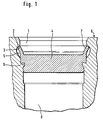
- Fig. 1 shows schematically the proposed according to the invention Locking device, the one in profile section essentially pot-shaped cross section of a closing body 4 shows that by means of a self-locking and Spread fastening is attached in a stepped bore.
- the self-caulking point between the housing bore and the closing body 4 is by the in an indentation 9
- Closing body 4 plastically displaced material of the housing 6 shown.
- the closing body 4 has on both sides of the Deformation 9 on the outer bore portion 1 and a inner bore section 8 adapted accordingly Piston sections with different diameters on, which during the pressing process of the closing body 4th the forming process of the housing material in the stepped bore favor in the indentation 9.
- the indentation 9 is comparable to a flute on the closing body 4 circumferential recess, in addition to the holding force a metallic seal causes.
- the in the area of outer bore section 1 formed on the closing body 4 Edge forms a collar 7, the end face in the Function of a support surface 3 in the arcuate recess 5 of the outer bore section 1 abuts.
- the collar 7 is shown in the spread state by an arch section in the recess 5 as a support surface 2 for Transfer of the holding force (axial force) contributes.
- the recess 5 in the housing 6 is also like the indentation 9 on the closing body 4 within certain limits with regard to Geometry freely selectable, so that regarding the design the introduced in the outer bore section 1 Recess 5 certain geometric changes are permitted.
- the spreading of the collar 7 is to be chosen such that the sealing effect of the housing material under all operating conditions remains in the indentation 9, which is why the support surface 3 on the collar 7 primarily for Power transmission should contribute.
- the support surface 3 on the collar 7 primarily for Power transmission should contribute.
- any between the support surface 3 on the collar 7 and the support surface 2 on the housing 6 remaining minimum game after the spread like this is small that any due to the high hydraulic operating pressure caused deformation of the Self-caulking through timely support effect of the Collar 7 is caught in the recess 5 to prevent leaks prevent at the self-restraining point.
- a high mechanical stress on the collar 7 is due whose essentially rectangular cross-section ensures in the direction of the vertical axis accordingly has a large area moment of inertia.
- the closing body 4 is consequently not the expansion process of the collar 7 necessarily limited to an externally initiated forming process, but can be done automatically.
- the collar 7 therefore, as shown in the figure, does not have to be a perimeter can form a largely closed unit be tongue-shaped.
- a relative easy to manufacture rotationally symmetrical component created is that in a first step in the step bore provided with a recess 5 the housing 6 is pressed until the housing material the indentation 9 on the closing body 4 to produce a Holding and sealing force shaped accordingly, whereby by a subsequent widening of the straight line extending and to the inner diameter of the outer bore portion 1 customized collar 7 an additional Holding device for the closing body 4 created in the bore is.
Landscapes
- Engineering & Computer Science (AREA)
- General Engineering & Computer Science (AREA)
- Mechanical Engineering (AREA)
- Pressure Vessels And Lids Thereof (AREA)
- Pistons, Piston Rings, And Cylinders (AREA)
- Insertion Pins And Rivets (AREA)
Claims (5)
- Dispositif d'obturation, constitué d'un obturateur (4) qui est emboíté à force dans un conduit d'un boítier (6) et sur la périphérie extérieure duquel est disposée au moins une partie formée en retrait (9) dans laquelle, lorsqu'on enfonce l'obturateur (4) dans le conduit, de la matière de base du boítier (6) est refoulée de façon à réaliser une solidarisation par complémentarité de formes, le conduit étant réalisé sous forme d'un alésage étagé dont une section d'alésage extérieure (1) de plus grand diamètre, orientée à l'opposé du côté du fluide sous pression, se raccorde au moyen d'un épaulement à une section d'alésage intérieure (8) de plus petit diamètre, orientée du côté du fluide sous pression, tandis que l'obturateur (4) comporte deux sections en forme de piston, de diamètres de grandeurs différentes et correspondant aux deux sections d'alésage (1, 8), entre lesquelles est réalisée la partie formée en retrait (9) qui est en contre-dépouille par rapport au plus petit diamètre et dans laquelle la matière de base réalisant la solidarisation par complémentarité de formes est repoussée à force par déformation plastique, caractérisé en ce que, sur la section d'alésage extérieure (1) orientée à l'opposé du côté du fluide sous pression, il est prévu au moins une surface d'appui (2) qui fait partie d'un logement (5) ménagé dans le boítier (6) et sur laquelle prend appui, au moyen d'un élargissement, une surface d'appui (3) de l'obturateur (4) qui est orientée vers le côté extérieur du boítier.
- Dispositif d'obturation suivant la revendication 1, caractérisé en ce qu'un collet (7), qui est réalisé sur l'obturateur (4) et dont la surface frontale forme la surface d'appui (3) de l'obturateur (4), vient en contact sur la surface d'appui (2) ménagée sur la section d'alésage extérieure (1).
- Dispositif d'obturation suivant la revendication 2, caractérisé en ce que le collet (7) s'accroche dans le logement (5).
- Procédé d'obturation de conduits, ménagés dans un boítier (6) et transportant un fluide sous pression, au moyen d'un obturateur (4) qui doit être emboíté à force dans un conduit et sur la périphérie extérieure duquel est disposée au moins une partie formée en retrait (9) dans laquelle, lorsqu'on enfonce l'obturateur (4) dans le conduit, de la matière de base du boítier (6) est refoulée de façon à réaliser une solidarisation par complémentarité de formes, le conduit étant réalisé sous forme d'un alésage étagé dont une section d'alésage extérieure (1) de plus grand diamètre, orientée à l'opposé du côté du fluide sous pression, se raccorde au moyen d'un épaulement à une section d'alésage intérieure (8) de plus petit diamètre, orientée du côté du fluide sous pression, tandis que l'obturateur (4) comporte deux sections en forme de piston, de diamètres de grandeurs différentes et correspondant aux deux sections d'alésage (1, 8), entre lesquelles est réalisée la partie formée en retrait (9) qui est en contre-dépouille par rapport au plus petit diamètre et dans laquelle la matière de base réalisant la solidarisation par complémentarité de formes est repoussée à force par déformation plastique, l'obturateur (4) exécutant, sous l'action d'une force d'enfoncement de direction et grandeur définies, un mouvement d'avance dirigé dans la section d'alésage intérieure (8), tandis que la matière du boítier qui réalise la solidarisation par complémentarité de formes de type plastique sur la partie formée en retrait (9) de l'obturateur (4) est refoulé dans la partie formée en retrait (9), caractérisé en ce qu'ensuite, une surface d'appui (3) située sur l'obturateur (4) et orientée vers le côté extérieur du boítier est élargie dans un logement (5) ménagé sur la section d'alésage extérieure (1).
- Procédé suivant la revendication 4, caractérisé en ce que la surface d'appui (3) de l'obturateur (4) qui est orientée vers le côté extérieur du boítier est formée par la surface frontale d'un collet (7) qui est formé sur l'obturateur (4) et qui est élargi d'une manière plastique en direction du logement (5), par un outil introduit dans la section d'alésage extérieure et appliqué sur le bord intérieur du collet (7), jusqu'à ce que la surface d'appui (3) de l'obturateur (4) s'étende dans le logement (5).
Applications Claiming Priority (3)
| Application Number | Priority Date | Filing Date | Title |
|---|---|---|---|
| DE4415341 | 1994-05-02 | ||
| DE4415341A DE4415341A1 (de) | 1994-05-02 | 1994-05-02 | Verschlußvorrichtung zum Verschließen von Druckmittel führenden Kanälen in einem Gehäuse |
| PCT/EP1995/001532 WO1995030108A1 (fr) | 1994-05-02 | 1995-04-22 | Systeme de fermeture pour obturer des conduites d'acheminement de substances sous pression dans un boitier |
Publications (2)
| Publication Number | Publication Date |
|---|---|
| EP0759134A1 EP0759134A1 (fr) | 1997-02-26 |
| EP0759134B1 true EP0759134B1 (fr) | 2000-01-05 |
Family
ID=6517017
Family Applications (1)
| Application Number | Title | Priority Date | Filing Date |
|---|---|---|---|
| EP95918591A Expired - Lifetime EP0759134B1 (fr) | 1994-05-02 | 1995-04-22 | Systeme d'obturation et procede pour obturer des conduites de fluides sous pression dans un boitier |
Country Status (5)
| Country | Link |
|---|---|
| US (1) | US5848616A (fr) |
| EP (1) | EP0759134B1 (fr) |
| JP (1) | JPH09512621A (fr) |
| DE (2) | DE4415341A1 (fr) |
| WO (1) | WO1995030108A1 (fr) |
Families Citing this family (45)
| Publication number | Priority date | Publication date | Assignee | Title |
|---|---|---|---|---|
| DE29617483U1 (de) * | 1996-10-08 | 1996-12-12 | Air Fröhlich AG für Energierückgewinnung, Arbon | Rohr, insbesondere Wärmetauscherrohr |
| NL1007976C2 (nl) * | 1998-01-07 | 1999-07-08 | Metaalgieterij Giesen B V | Werkwijze en afdichtstop voor het afdichten van een kerngat in een gietstuk. |
| DE19902038A1 (de) | 1999-01-20 | 2000-07-27 | Continental Teves Ag & Co Ohg | Verschlußvorrichtung |
| AU1034700A (en) * | 1999-10-11 | 2001-04-23 | Nokia Networks Oy | A method for identifying bad frames |
| JP2002139290A (ja) * | 2000-10-31 | 2002-05-17 | Toyo Radiator Co Ltd | モジュールタイプ熱交換器およびその製造方法 |
| DE20114778U1 (de) * | 2001-09-06 | 2002-02-07 | AB SKF, Gödeborg | Topfförmiges Blechteil |
| US20050150097A1 (en) * | 2004-01-09 | 2005-07-14 | Jones Ronald E. | Cold process for joining metal |
| US8075668B2 (en) | 2005-03-29 | 2011-12-13 | Dresser-Rand Company | Drainage system for compressor separators |
| JP4067016B2 (ja) * | 2005-11-17 | 2008-03-26 | ダイキン工業株式会社 | 管継手の蓋構造、仕切り蓋、冷凍装置、ヒートポンプ式給湯機、給水配管、配管の接続方法、及び現地配管施工方法 |
| ITPC20060005U1 (it) * | 2006-04-03 | 2007-10-04 | Fulgosi Giovanni Di Cerri Corr | Portello per l'apertura e chiusura di condotte in pressione in particoare per l'apertura e la chiusura delle derivazioni per l'introduzione di apparecchi per la pulizia e il controllo delle condotte |
| WO2008036221A2 (fr) | 2006-09-19 | 2008-03-27 | Dresser-Rand Company | Joint rotatif pour séparateur à tambour |
| MX2009003119A (es) | 2006-09-21 | 2009-04-06 | Dresser Rand Co | Tambor separador y ensamble propulsor de compresor. |
| CA2663751C (fr) | 2006-09-25 | 2015-01-27 | William C. Maier | Couvercle d'acces pour tiroir de liaison sous pression |
| MX2009003177A (es) | 2006-09-25 | 2009-04-03 | Dresser Rand Co | Bobina conectora axialmente movil. |
| BRPI0718451A2 (pt) | 2006-09-25 | 2013-11-26 | Dresser Rand Co | Defletor de fluido para dispositivos separadores de fluido |
| US8061737B2 (en) | 2006-09-25 | 2011-11-22 | Dresser-Rand Company | Coupling guard system |
| CA2663880C (fr) | 2006-09-25 | 2015-02-10 | William C. Maier | Systeme de montage pour compresseur |
| MX2009003255A (es) | 2006-09-26 | 2009-04-07 | Dresser Rand Co | Dispositivo separador de fluido estatico mejorado. |
| DE102007057030A1 (de) | 2007-11-27 | 2009-05-28 | Robert Bosch Gmbh | Druckbegrenzungsventil sowie Pumpenaggregat mit Druckbegrenzungsventil |
| US8408879B2 (en) | 2008-03-05 | 2013-04-02 | Dresser-Rand Company | Compressor assembly including separator and ejector pump |
| SE532352C2 (sv) * | 2008-04-14 | 2009-12-22 | Sapa Profiler Ab | Metod och förband för tätning |
| US8062400B2 (en) | 2008-06-25 | 2011-11-22 | Dresser-Rand Company | Dual body drum for rotary separators |
| US7922218B2 (en) | 2008-06-25 | 2011-04-12 | Dresser-Rand Company | Shear ring casing coupler device |
| US8079805B2 (en) | 2008-06-25 | 2011-12-20 | Dresser-Rand Company | Rotary separator and shaft coupler for compressors |
| US8087901B2 (en) | 2009-03-20 | 2012-01-03 | Dresser-Rand Company | Fluid channeling device for back-to-back compressors |
| US8210804B2 (en) | 2009-03-20 | 2012-07-03 | Dresser-Rand Company | Slidable cover for casing access port |
| US8061972B2 (en) | 2009-03-24 | 2011-11-22 | Dresser-Rand Company | High pressure casing access cover |
| JP5353472B2 (ja) * | 2009-06-23 | 2013-11-27 | 株式会社アドヴィックス | 詰栓構造 |
| EP2478229B1 (fr) | 2009-09-15 | 2020-02-26 | Dresser-Rand Company | Séparateur compact basé sur une densité améliorée |
| EP2533905B1 (fr) | 2010-02-10 | 2018-07-04 | Dresser-Rand Company | Collecteur de fluide séparateur et procédé |
| JP5642434B2 (ja) * | 2010-06-21 | 2014-12-17 | 三徳商事株式会社 | パイプ接続構造 |
| WO2012009159A2 (fr) | 2010-07-15 | 2012-01-19 | Dresser-Rand Company | Ensemble d'aubes radiales pour séparateurs rotatifs |
| WO2012009158A2 (fr) | 2010-07-15 | 2012-01-19 | Dresser-Rand Company | Séparateur rotatif en ligne amélioré |
| WO2012012018A2 (fr) | 2010-07-20 | 2012-01-26 | Dresser-Rand Company | Séparation améliorée par détente et refroidissement combinés |
| WO2012012143A2 (fr) | 2010-07-21 | 2012-01-26 | Dresser-Rand Company | Faisceau de séparateurs rotatifs modulaires multiples en ligne |
| EP2614216B1 (fr) | 2010-09-09 | 2017-11-15 | Dresser-Rand Company | Drain à écoulement contrôlé permettant le rinçage |
| US8994237B2 (en) | 2010-12-30 | 2015-03-31 | Dresser-Rand Company | Method for on-line detection of liquid and potential for the occurrence of resistance to ground faults in active magnetic bearing systems |
| WO2013109235A2 (fr) | 2010-12-30 | 2013-07-25 | Dresser-Rand Company | Procédé de détection en ligne de défauts de résistance à la masse dans des systèmes de palier magnétique actif |
| US9551349B2 (en) | 2011-04-08 | 2017-01-24 | Dresser-Rand Company | Circulating dielectric oil cooling system for canned bearings and canned electronics |
| DE102011018475A1 (de) | 2011-04-21 | 2012-10-25 | Rwm Schweiz Ag | Vorrichtung und Verfahren zur luftdichten Abdeckung einer Leuchtspur oder dergleichen |
| EP2715167B1 (fr) | 2011-05-27 | 2017-08-30 | Dresser-Rand Company | Roulement segmenté à décélération en roue libre pour des systèmes de roulement magnétique |
| US8851756B2 (en) | 2011-06-29 | 2014-10-07 | Dresser-Rand Company | Whirl inhibiting coast-down bearing for magnetic bearing systems |
| US9611897B2 (en) * | 2015-04-08 | 2017-04-04 | Ntn Bearing Corporation Of America | Grease retention assembly for a joint of a vehicle drive shaft |
| US20190217429A1 (en) * | 2018-01-16 | 2019-07-18 | General Electric Company | Systems and methods for resizing holes |
| DE102019105507A1 (de) * | 2019-03-05 | 2020-09-10 | Volkswagen Aktiengesellschaft | Strömungstechnisch druckverlustoptimierte Verschlusselemente (Stopfen) für Fluidkanäle, insbesondere in Getriebe- und Motorgehäusen |
Family Cites Families (28)
| Publication number | Priority date | Publication date | Assignee | Title |
|---|---|---|---|---|
| DE538132C (de) * | 1931-11-11 | Robert Bosch Akt Ges | Stopfen zum dichten Abschliessen eines Loches | |
| US208292A (en) * | 1878-09-24 | Improvement in emptying-valves for paper-pulp engines | ||
| US1620728A (en) * | 1925-07-10 | 1927-03-15 | Walsh & Weidner Boiler Co | Closure plug for pipes |
| US1686562A (en) * | 1927-06-20 | 1928-10-09 | Jackson Percy | Process of forming pipe closures |
| US1929824A (en) * | 1931-05-12 | 1933-10-10 | French Oil Mill Machinery | Press plate or the like and method of making the same |
| US1946065A (en) * | 1932-06-27 | 1934-02-06 | Lubrication Corp | Lubricating device |
| US2010569A (en) * | 1934-03-28 | 1935-08-06 | Florence Pipe Foundry & Machin | Method of plugging holes in plates |
| US2138404A (en) * | 1934-10-12 | 1938-11-29 | Baldwin Southwark Corp | Method for inserting and holding closure plugs |
| US3325891A (en) * | 1964-09-29 | 1967-06-20 | Westinghouse Air Brake Co | Method of closing core pin holes |
| US3270793A (en) * | 1964-10-05 | 1966-09-06 | Anthony P Polmon | Threaded insert |
| US3387735A (en) * | 1966-08-31 | 1968-06-11 | Fluid Controls Inc | Metal insert for wall openings and method of combining the same therewith |
| US3560030A (en) * | 1967-05-11 | 1971-02-02 | Fred Macks | Closures |
| US3555656A (en) * | 1967-05-25 | 1971-01-19 | Westinghouse Electric Corp | Method of explosively plugging a leaky metal tube in a heat exchanger tube bundle |
| US3451583A (en) * | 1968-05-20 | 1969-06-24 | Lee Co | Expandable sealing plug |
| US3571903A (en) * | 1968-12-13 | 1971-03-23 | Ibm | Method of securing a self-piercing and clinching element to a sheet of metal |
| US3578027A (en) * | 1969-07-30 | 1971-05-11 | William L Zopfi | Sealing plugs or closures |
| CH508828A (de) * | 1970-07-08 | 1971-06-15 | Hirmann Georg | Verfahren zum Verschliessen von Bohrungen in Werkstücken und Stopfen zur Ausführung des Verfahrens |
| NL7109253A (fr) * | 1970-07-08 | 1972-01-11 | ||
| US4046168A (en) * | 1974-09-30 | 1977-09-06 | Mm Plastic (Mfg) Company, Inc. | Closure plugs |
| US4170247A (en) * | 1977-10-25 | 1979-10-09 | John Bates | Polyfluorocarbon condenser plug |
| US4682707A (en) * | 1985-01-11 | 1987-07-28 | National Can Corporation | Container having a tamper proof lid |
| JPH0341168Y2 (fr) * | 1985-08-05 | 1991-08-29 | ||
| DE8716060U1 (de) * | 1987-12-04 | 1989-04-13 | Robert Bosch Gmbh, 7000 Stuttgart | Verschlußvorrichtung zum Abschließen von Druckmittel führenden Bohrungen oder Kanälen |
| US4987672A (en) * | 1989-07-28 | 1991-01-29 | Fuji Valve Co., Ltd. | Method of partitioning the internal space of a hollow cylindrical member |
| JP2975430B2 (ja) * | 1989-12-22 | 1999-11-10 | フォルクスワーゲン・アクチェンゲゼルシャフト | もどり止め装置 |
| US5311910A (en) * | 1991-02-20 | 1994-05-17 | Kabushiki Kaisha Showa Seisakusho | Cap attachment structure for accumulator |
| US5194214A (en) * | 1991-05-13 | 1993-03-16 | Westinghouse Electric Corp. | Tube plug and method for plugging a tube |
| DE4142153A1 (de) * | 1991-12-20 | 1993-06-24 | Bosch Gmbh Robert | Verschluss fuer druckmittelfuehrende bohrungen oder kanaele in einem gehaeuse |
-
1994
- 1994-05-02 DE DE4415341A patent/DE4415341A1/de not_active Withdrawn
-
1995
- 1995-04-22 DE DE59507580T patent/DE59507580D1/de not_active Expired - Lifetime
- 1995-04-22 JP JP7527974A patent/JPH09512621A/ja active Pending
- 1995-04-22 US US08/737,052 patent/US5848616A/en not_active Expired - Lifetime
- 1995-04-22 WO PCT/EP1995/001532 patent/WO1995030108A1/fr active IP Right Grant
- 1995-04-22 EP EP95918591A patent/EP0759134B1/fr not_active Expired - Lifetime
Also Published As
| Publication number | Publication date |
|---|---|
| EP0759134A1 (fr) | 1997-02-26 |
| JPH09512621A (ja) | 1997-12-16 |
| DE4415341A1 (de) | 1995-11-09 |
| DE59507580D1 (de) | 2000-02-10 |
| US5848616A (en) | 1998-12-15 |
| WO1995030108A1 (fr) | 1995-11-09 |
Similar Documents
| Publication | Publication Date | Title |
|---|---|---|
| EP0759134B1 (fr) | Systeme d'obturation et procede pour obturer des conduites de fluides sous pression dans un boitier | |
| DE19960335B4 (de) | Hydraulikzylinder | |
| EP0923476A1 (fr) | Electrovanne pour systeme de freinage hydraulique et a regulation anti-patinage pour vehicules | |
| WO2000025080A1 (fr) | Raccord de tuyauterie entre un collecteur de l'echangeur thermique d'un vehicule automobile et une conduite exterieure | |
| WO2002042676A1 (fr) | Dispositif de raccord d'une conduite de fluide | |
| DE10353306A1 (de) | Dichtring | |
| DE19981050B4 (de) | Führungshülse für einen Nehmerzylinder | |
| EP2356365B1 (fr) | Dispositif de fermeture | |
| EP1514031B1 (fr) | Liaison par vis comportant un col d'etancheite | |
| DE69331337T2 (de) | Federspeicherbremszylinder und bolzenverriegelung dafür | |
| EP2635838B1 (fr) | Élément, en particulier élément d'obturation | |
| DE19953475A1 (de) | Montagewerkzeug | |
| DE102009007330A1 (de) | Fahrzeugscheibenbremse | |
| DE3416702C2 (de) | Schlaucharmatur | |
| DE102014201911B4 (de) | Aktuator für einen elektrohydraulischen Gaswechselventiltrieb einer Brennkraftmaschine | |
| EP1317328B1 (fr) | POINçON DE MATAGE ET UTILISATION D'UN TEL POINçON | |
| DE19948425B4 (de) | Verschlußvorrichtung zum Verschließen von Bohrungen in einem Gehäuse | |
| DE69100818T2 (de) | Halteorgan für einen Dichtungsring verschiebbar in einem teleskopischen System. | |
| DE8716060U1 (de) | Verschlußvorrichtung zum Abschließen von Druckmittel führenden Bohrungen oder Kanälen | |
| DE10049047C2 (de) | Verfahren zum Herstellen einer Nockenwelle und danach hergestellte Nockenwelle | |
| EP0831244B1 (fr) | Actionneur pour frein à disque et son procédé de fabrication | |
| DE102018110030B4 (de) | Hydraulische Spannvorrichtung für einen Kettentrieb | |
| DE3336304C2 (fr) | ||
| DE10033060B4 (de) | Verfahren zur Herstellung eines Zylinders mit einem endseitig geschlossenen Boden | |
| EP1147322B1 (fr) | Dispositif de fermeture pour canaux acheminant des milieux sous pression |
Legal Events
| Date | Code | Title | Description |
|---|---|---|---|
| PUAI | Public reference made under article 153(3) epc to a published international application that has entered the european phase |
Free format text: ORIGINAL CODE: 0009012 |
|
| 17P | Request for examination filed |
Effective date: 19961202 |
|
| AK | Designated contracting states |
Kind code of ref document: A1 Designated state(s): DE FR GB |
|
| RAP1 | Party data changed (applicant data changed or rights of an application transferred) |
Owner name: CONTINENTAL TEVES AG & CO. OHG |
|
| GRAG | Despatch of communication of intention to grant |
Free format text: ORIGINAL CODE: EPIDOS AGRA |
|
| 17Q | First examination report despatched |
Effective date: 19990323 |
|
| GRAG | Despatch of communication of intention to grant |
Free format text: ORIGINAL CODE: EPIDOS AGRA |
|
| GRAH | Despatch of communication of intention to grant a patent |
Free format text: ORIGINAL CODE: EPIDOS IGRA |
|
| GRAH | Despatch of communication of intention to grant a patent |
Free format text: ORIGINAL CODE: EPIDOS IGRA |
|
| GRAA | (expected) grant |
Free format text: ORIGINAL CODE: 0009210 |
|
| AK | Designated contracting states |
Kind code of ref document: B1 Designated state(s): DE FR GB |
|
| GBT | Gb: translation of ep patent filed (gb section 77(6)(a)/1977) |
Effective date: 20000106 |
|
| REF | Corresponds to: |
Ref document number: 59507580 Country of ref document: DE Date of ref document: 20000210 |
|
| ET | Fr: translation filed | ||
| PGFP | Annual fee paid to national office [announced via postgrant information from national office to epo] |
Ref country code: GB Payment date: 20000323 Year of fee payment: 6 |
|
| PLBE | No opposition filed within time limit |
Free format text: ORIGINAL CODE: 0009261 |
|
| STAA | Information on the status of an ep patent application or granted ep patent |
Free format text: STATUS: NO OPPOSITION FILED WITHIN TIME LIMIT |
|
| 26N | No opposition filed | ||
| PG25 | Lapsed in a contracting state [announced via postgrant information from national office to epo] |
Ref country code: GB Free format text: LAPSE BECAUSE OF NON-PAYMENT OF DUE FEES Effective date: 20010422 |
|
| GBPC | Gb: european patent ceased through non-payment of renewal fee |
Effective date: 20010422 |
|
| PGFP | Annual fee paid to national office [announced via postgrant information from national office to epo] |
Ref country code: FR Payment date: 20060418 Year of fee payment: 12 |
|
| PGFP | Annual fee paid to national office [announced via postgrant information from national office to epo] |
Ref country code: DE Payment date: 20060430 Year of fee payment: 12 |
|
| PG25 | Lapsed in a contracting state [announced via postgrant information from national office to epo] |
Ref country code: DE Free format text: LAPSE BECAUSE OF THE APPLICANT RENOUNCES Effective date: 20060516 |
|
| PG25 | Lapsed in a contracting state [announced via postgrant information from national office to epo] |
Ref country code: FR Free format text: LAPSE BECAUSE OF NON-PAYMENT OF DUE FEES Effective date: 20070430 |