EP2000705B1 - Appareil de changement de vitesses - Google Patents
Appareil de changement de vitesses Download PDFInfo
- Publication number
- EP2000705B1 EP2000705B1 EP08157052A EP08157052A EP2000705B1 EP 2000705 B1 EP2000705 B1 EP 2000705B1 EP 08157052 A EP08157052 A EP 08157052A EP 08157052 A EP08157052 A EP 08157052A EP 2000705 B1 EP2000705 B1 EP 2000705B1
- Authority
- EP
- European Patent Office
- Prior art keywords
- shift lever
- shift
- mode
- neutral
- home position
- Prior art date
- Legal status (The legal status is an assumption and is not a legal conclusion. Google has not performed a legal analysis and makes no representation as to the accuracy of the status listed.)
- Ceased
Links
- 230000005540 biological transmission Effects 0.000 claims description 34
- 230000007935 neutral effect Effects 0.000 description 42
- 230000008878 coupling Effects 0.000 description 2
- 238000010168 coupling process Methods 0.000 description 2
- 238000005859 coupling reaction Methods 0.000 description 2
- 230000004048 modification Effects 0.000 description 2
- 238000012986 modification Methods 0.000 description 2
Images

Classifications
-
- F—MECHANICAL ENGINEERING; LIGHTING; HEATING; WEAPONS; BLASTING
- F16—ENGINEERING ELEMENTS AND UNITS; GENERAL MEASURES FOR PRODUCING AND MAINTAINING EFFECTIVE FUNCTIONING OF MACHINES OR INSTALLATIONS; THERMAL INSULATION IN GENERAL
- F16H—GEARING
- F16H59/00—Control inputs to control units of change-speed- or reversing-gearings for conveying rotary motion
- F16H59/02—Selector apparatus
- F16H59/08—Range selector apparatus
- F16H59/10—Range selector apparatus comprising levers
-
- Y—GENERAL TAGGING OF NEW TECHNOLOGICAL DEVELOPMENTS; GENERAL TAGGING OF CROSS-SECTIONAL TECHNOLOGIES SPANNING OVER SEVERAL SECTIONS OF THE IPC; TECHNICAL SUBJECTS COVERED BY FORMER USPC CROSS-REFERENCE ART COLLECTIONS [XRACs] AND DIGESTS
- Y10—TECHNICAL SUBJECTS COVERED BY FORMER USPC
- Y10T—TECHNICAL SUBJECTS COVERED BY FORMER US CLASSIFICATION
- Y10T74/00—Machine element or mechanism
- Y10T74/19—Gearing
- Y10T74/19219—Interchangeably locked
- Y10T74/19251—Control mechanism
-
- Y—GENERAL TAGGING OF NEW TECHNOLOGICAL DEVELOPMENTS; GENERAL TAGGING OF CROSS-SECTIONAL TECHNOLOGIES SPANNING OVER SEVERAL SECTIONS OF THE IPC; TECHNICAL SUBJECTS COVERED BY FORMER USPC CROSS-REFERENCE ART COLLECTIONS [XRACs] AND DIGESTS
- Y10—TECHNICAL SUBJECTS COVERED BY FORMER USPC
- Y10T—TECHNICAL SUBJECTS COVERED BY FORMER US CLASSIFICATION
- Y10T74/00—Machine element or mechanism
- Y10T74/20—Control lever and linkage systems
- Y10T74/20012—Multiple controlled elements
- Y10T74/20018—Transmission control
- Y10T74/20085—Restriction of shift, gear selection, or gear engagement
- Y10T74/20104—Shift element interlock
- Y10T74/20116—Resiliently biased interlock
Definitions
- the present invention relates to a shift apparatus operable to electrically switch a coupling mode of a transmission in accordance with a shifting operation in a shift-by-wire system, according to the preamble of claim 1 and as it is disclosed in DE 202004004151 U .
- Shift apparatuses of a shift-by-wire system have, for example, a shift lever of a joystick-type, and an actuator operable to switch a coupling mode of an automatic transmission when the actuator is electrically operated in accordance with a driver's operation of the shift lever.
- Fig. 5 is an explanatory view of a related-art shift apparatus 100 disclosed in JP 2005-504685 A .
- a shift lever of the shift apparatus 100 has a home position X, a neutral position N on a left side of the home position X, a reverse position R on a front side of the neutral position N, and a drive position D on a rear side of the neutral position N.
- the shift apparatus 100 is configured such that, when the shift lever is released from a driver's hand after being moved from the home position X to any of the positions R, N and D, the shift lever is automatically returned to the original home position X.
- a first direction a' from the home position X toward the neutral position N and a second direction b' from the neutral position N toward the reverse position R are not opposite from each other, while the second direction b' and a third direction c' from the neutral position N toward the drive position D are opposite directions.
- the shift lever can be easily operated to move from the home position X to the neutral position N, simply by linearly moving the shift lever toward the left from the home position X.
- the shift lever may be erroneously operated to move from the home position X to the neutral position N due to an unintentional external force applied to the shift lever in a leftward direction f', for example, when the shift lever is accidentally hit by an elbow of the driver.
- the shift lever In order to operate the shift lever to move from the home position X to the drive position D or to the reverse position R, the shift lever is firstly moved from the home position X to the neutral position N, and then a direction in which the shift lever is to be moved from the neutral position N is changed by 90 degrees. If the shift lever is a joystick-type, operability of the shift lever improves in that the shift lever may also be operated in an obliquely leftward direction d' or e' when moving the shift lever from the home position X to the drive position D or to the reverse position R.
- the shift lever may be erroneously operated to move to the drive position D or to the reverse position R due to an unintentional external force applied to the shift lever in the obliquely leftward direction d' or e', for example, when the shift lever is accidentally hit by an elbow of the driver.
- shift apparatus includes a shift lever operable to select a first mode of a transmission when the shift lever is disposed at a first position and to select a second mode of the transmission when the shift lever is disposed at a second position, and a base supporting the shift lever.
- the shift lever automatically returns to a home position after selecting the first mode or the second mode.
- the shift lever is moved in a first direction and then in a second direction which is different from the first direction and not directly opposite to the first direction.
- the shift apparatus is characterized in that when moving the shift lever from the first position to the second position to select the second mode, the shift lever is moved in a third direction which is different from the first direction and the second direction and not directly opposite to the second direction.
- the first mode may be, for example, a neutral mode
- the second mode may be, for example a reverse mode or a drive mode.
- the first to third directions are operating directions of the shift lever upon selecting the respect modes of the transmission, and may be, for example, a rearward direction, a leftward direction, a forward direction respectively.
- the first mode of the transmission is selected by sequentially moving the shift lever, from the home position, in the first direction and then in the second direction.
- the second direction is different from the first direction and is not directly opposite to the first direction. Therefore, the shift lever is prevented from being erroneously operated even when an unintentional force is applied to the shift lever in the first direction, since the shift lever needs to be further moved in the second direction in order to select the first mode.
- the second mode is selected by moving the shift lever, from the first position, in the third direction which is different from the first and second directions and is not directly opposite to the second direction. That is, in order to move the shift lever from the home position to the second shift position, the shift lever needs to be operated in the first, second and third directions. Therefore, the shift lever is prevented from being erroneously operated due to an unintentional external force to the shift lever.
- the shift lever may be further operable to select a third mode of the transmission when the shift lever is disposed at a third shift position.
- the shift lever is moved in a fourth direction.
- the fourth direction is different from the third direction and is parallel to the first direction.
- the shift lever when moving the shift lever to the third position, the shift lever needs to be moved in the fourth direction from the first position. Therefore, the shift lever is prevented from being erroneously operated to select the third mode even if to an unintentional external force is applied to the shift lever.
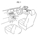
- Fig. 1 is a perspective view showing a shift apparatus according to an exemplary embodiment of the present invention
- a top and a bottom of the drawings will be “front” and “rear” while a right and a left of the drawings will be “right” and “left” as it is for convenience of explanation, although the respective directions are actually optional since they depend on a location and an orientation of a shift apparatus.
- An automatic transmission is a device which automatically performs an operation of a clutch and transmission system.
- the automatic transmission has, for example, a reverse mode corresponding to a reverse position R in the shift apparatus 1, a neutral mode corresponding to a neutral position N in the shift apparatus 1, and a drive mode corresponding to a drive position D in the shift apparatus 1.
- a driver can select the respective modes of the automatic transmission by operating a shift lever 2 of the shift apparatus 1.
- the automatic transmission is electrically coupled to the shift apparatus 1 and a control unit (not shown), and is controlled by the control unit in accordance with a signal, i.e., shift selection signal from the shift apparatus 1.
- the shift apparatus 1 has the shift lever 2 for selecting the modes of the automatic transmission.
- the shift lever 2 is movable, for example, to four shift positions, namely a home position X, the neutral position N (a first shift position), the reverse position R (a second shift position), and the drive position D (a third shift position).
- the shift apparatus 1 further includes a base 3 supporting the shift lever 2, a click mechanism (not shown) operable to provide a feeling of a click when the shift lever 2 is operated from the home position X to the neutral position N, and a shift position switch (not shown) operable to detect the respective positions of the shift lever 2.
- the shift apparatus 1 is attached to an instrument panel IP between a driver seat and a front passenger seat such that the shift lever 2 is protruded therefrom.
- the shift lever 2 may be a joystick having a knob 31 at an upper end portion thereof, as shown in Fig. 1 .
- the base 3 has an escutcheon through which the shift lever 2 is inserted and a case (not shown) disposed below the escutcheon.
- the shift lever 2 is pivotably supported by the base 3 so as to be movable in front, rear, right and leftward directions.
- the escutcheon 3 is an ornamental plate on which characters "R”, “N”, “D” and “X”, each indicating the respective shift positions R, N, D, X of the shift lever 2, are marked, and may be attached to the instrument panel IP.
- the home position X is arranged on a right front side.
- the home position X is a position to which the shift lever 2 is automatically returned after being moved to the neutral position N, the reverse position R, or the drive position D.
- the neutral position N is a position corresponding to the neutral mode of the automatic transmission.
- the neutral position N is selectable by sequentially operating the shift lever 2, from the home position X, in a rearward direction a (a first direction) and then in a leftward direction b (a second direction) which is different from the rearward direction a and is not directly opposite to the rearward direction a.
- the reverse position R is a position corresponding to the reverse mode of the automatic transmission.
- the reverse position R is selectable by operating the shift lever 2, from the neutral position N, in a forward direction c (a third direction) which is different from the rearward direction a (the first direction) and the leftward direction b (the second direction) and is not directly opposite to the leftward direction b.
- the drive position D is a position corresponding to the drive mode of the automatic transmission, and is selectable by operating the shift lever 2, from the neutral position N, in a rearward direction d (a fourth direction) which is parallel to the direction a.
- the click mechanism is operable to guide a operating direction of the shift lever 2, which is pivoted in accordance with a shifting operation by the driver, while preventing an unnecessary play of the shift lever 2.
- the click mechanism provides a feeling of a click upon the shifting operation of the shift lever 2.
- the click mechanism includes a groove which is formed along operation paths of the shift lever 2 extending from the home position X to the respective positions N, R, D to support the shift lever 2 such that the shift lever 2 is automatically returned to the home position X, a pin which is brought into press-contact with the groove, and a spring biasing the pin. More specifically, the groove is formed along the rearward directions a, d, the leftward direction b, and the forward direction c as shown in Fig. 2 .
- the click mechanism may be similar to a detent mechanism of a shift apparatus disclosed in JP 2006-347308 A .
- the shift position switch is operable to detect the respective positions of the shift lever 2.
- the shift position switch includes a magnet (a movable contact) which moves together with the shift lever 2, and a hall element (a fixed contact) for detecting a position of the magnet when the shift lever 2 is operated to respective positions.
- the shift selection signals corresponding to the respective positions of the shift lever 2 are output from the shift position switch to the control unit.
- the shift position switch may similar to a shift detecting device disclosed in JP 2006-347314 A .
- the shift lever 2 When the shift lever 2 is not operated by the driver, the shift lever 2 is automatically returned to the home position X by the click mechanism.
- the shift lever 2 When the shift lever 2 is disposed at the home position X, the shift lever 2 is supported such that the shift lever does not move even if an external force is applied to the shift lever 2 in right and leftward directions e, f or in a forward direction g.
- an external force is applied to the shift lever 2 in a rearward direction h, the shift lever 2 is moved in the rearward direction a (the first direction), and is stopped on a right side of the neutral position N.
- the shift lever 2 When selecting the neutral mode of the automatic transmission, the shift lever 2 is moved, from the home position X, in the rearward direction a and then in the leftward direction b.
- the shift lever 2 when operating the shift lever 2 from the home position X to the neutral position N, the shift lever 2 needs to be moved in the rearward direction a and then in the leftward direction b . Therefore, even when an external force is accidentally applied to the shift lever 2 in any of the directions e, f, g, h, e.g. by hitting the shift lever 2 with the elbow of the driver, the shift lever 2 is prevented from being erroneously moved to the neutral position N.
- the driver may apply force to the shift lever 2 in an obliquely rearward direction i , directly toward the neutral position N from the home position X, when selecting the neutral mode.
- the driver feels a click upon a change of the directions in which the shift lever 2 is moved. Therefore, even when the driver accidentally applies force to the shift lever 2 in the direction i, the click makes the driver notice the erroneous operation so that the driver can stop pushing the shift lever 2 to prevent the erroneous operation.
- the shift lever 2 is automatically returned to the home position X by moving back the respective paths along the direction b and the direction a while being guided by an inclined face of the groove of the click mechanism.
- the shift lever 2 When selecting the reverse mode of the automatic transmission, the shift lever 2 is moved, from the home position X, in the rearward direction a, the leftward direction b, and the forward direction c, in this order.
- the shift lever 2 needs to be operated in the forward direction c after being moved to the neutral position N.
- the shift lever 2 can be moved to the reverse position R by after operating the shift lever 2 from the home position X to the neutral position N by applying a force to the shift lever 2 in the obliquely rearward direction i from the neutral position N and then sequentially applying a force in the forward direction j .
- the shift lever 2 when moving the shift lever 2 from the home position X to the reverse position R, the shift lever 2 needs to be operated in the rearward direction a, the leftward direction b and the forward direction c in this order, or in the obliquely rearward direction i from the home position X toward the neutral position N and then in the forward direction j. Because the operating directions needs to be changed in this way in order to move the shift lever 2 to the reverse position R, the shift lever 2 is prevented from being erroneously operated due to an unintentional external force applied to the shift lever 2 in any of the directions e, f, g, h, e.g., a hit by the elbow of the driver.
- the shift lever 2 When the shift lever 2 is operated to be disposed at the reverse position R, the corresponding shift selection signal is transmitted from a shift position switch to the control unit, whereby the control unit converts the automatic transmission to be the reverse mode.
- the shift lever 2 is automatically returned to the home position X by moving back the respective paths along the direction c, the direction b and the direction a due to a spring force of the click mechanism.
- the shift lever 2 When selecting the drive mode of the automatic transmission, the shift lever 2 is moved, from the home position X, in the rearward direction a, the leftward direction b , and in the rearward direction d in this order.
- the shift lever 2 needs to be operated in the rearward direction d after being moved to the neutral position N.
- the shift lever 2 can be moved to the drive position D by applying a force to the shift lever 2 in an obliquely rearward direction k from the home position X directly toward the drive position D.
- the shift lever 2 is prevented from being erroneously operated even when an unintentional external force is accidentally applied to the shift lever 2 in any of the directions e, f, g, h, e.g. by hitting the shift lever 2 with the elbow. Further, even when an unintentional force is applied in the obliquely rearward direction k, the driver can recognize the erroneous operation by a feeling of the click.
- the shift lever 2 When the shift lever 2 is operated to be disposed at the drive position D, the corresponding shift selection signal is transmitted from a shift position switch to the control unit, whereby the control unit converts the automatic transmission to be the drive mode.
- the shift lever 2 is automatically returned to the home position X by moving back the respective paths along the direction d, the direction b, and the direction a due to the spring force of the click mechanism.
- the shift lever 2 of the shift apparatus 1 is movable to the four respective positions, namely the home position X the neutral position N, the reverse position R, and the drive position D.
- the number of position to be assigned to the shift lever is not limited to the four positions.
- the shift apparatus 1 may be configured such that the shift lever 2 is moved to a position D2 on a left side of the position D and/or to a position L on a right side of the position D, in which the positions D, D2, L correspond to different drive modes of the automatic transmission.
- the home position X may be arranged at a position other than the right front position as explained in the foregoing exemplary embodiments.
- the home position X may be arranged at a left front position as shown in Fig. 4B , or at a left rear position or a right rear position.
- the position of the reverse position R may be arranged at a position other than the front side position as explained in the foregoing exemplary embodiments.
- the reverse position R may be arranged at a left rear position as shown in Fig. 4C , or at a left front position or a right rear position.
- the shift apparatus 1 may also be configured to generate one or more additional clicks with the pin biased by the spring and one or more protrusions.
Landscapes
- Engineering & Computer Science (AREA)
- General Engineering & Computer Science (AREA)
- Mechanical Engineering (AREA)
- Arrangement Or Mounting Of Control Devices For Change-Speed Gearing (AREA)
Claims (2)
- Appareil de changement de vitesse (1) comprenant :un levier de changement de vitesse (2) pouvant fonctionner pour sélectionner un premier mode d'une transmission lorsque le levier de changement de vitesse (2) est disposé à une première position et pour sélectionner un deuxième mode de la transmission lorsque le levier de changement de vitesse (2) est disposé à une deuxième position ; etune base (3) supportant le levier de changement de vitesse,dans lequel le levier de changement de vitesse (2) retourne automatiquement à une position de référence après sélection du premier mode ou du deuxième mode,
dans lequel, lors du déplacement du levier de changement de vitesse (2) de la position de référence à la première position pour sélectionner le premier mode, le levier de changement de vitesse (2) est déplacé dans un premier sens et ensuite dans un deuxième sens qui est différent du premier sens et non directement opposé au premier sens, et caractérisé en ce que
lors du déplacement du levier de changement de vitesse (2) de la première position à la deuxième position pour sélectionner le deuxième mode, le levier de changement de vitesse (2) est déplacé dans un troisième sens qui est différent du premier sens et du deuxième sens et non directement opposé au deuxième sens. - Appareil de changement de vitesse (1) selon la revendication 1, dans lequel le levier de changement de vitesse (2) est encore utilisable pour sélectionner un troisième mode de la transmission lorsque le levier de changement de vitesse (2) est disposé à une troisième position de changement de vitesse, et
dans lequel, lors du déplacement du levier de changement de vitesse (2) de la première position à la troisième position pour sélectionner le troisième mode, le levier de changement de vitesse (2) est déplacé dans un quatrième sens qui est différent du troisième sens et est parallèle au premier sens.
Applications Claiming Priority (1)
| Application Number | Priority Date | Filing Date | Title |
|---|---|---|---|
| JP2007151248A JP4500327B2 (ja) | 2007-06-07 | 2007-06-07 | シフト装置 |
Publications (3)
| Publication Number | Publication Date |
|---|---|
| EP2000705A2 EP2000705A2 (fr) | 2008-12-10 |
| EP2000705A3 EP2000705A3 (fr) | 2009-02-25 |
| EP2000705B1 true EP2000705B1 (fr) | 2009-08-12 |
Family
ID=39766974
Family Applications (1)
| Application Number | Title | Priority Date | Filing Date |
|---|---|---|---|
| EP08157052A Ceased EP2000705B1 (fr) | 2007-06-07 | 2008-05-28 | Appareil de changement de vitesses |
Country Status (5)
| Country | Link |
|---|---|
| US (1) | US7966905B2 (fr) |
| EP (1) | EP2000705B1 (fr) |
| JP (1) | JP4500327B2 (fr) |
| CN (1) | CN101318468B (fr) |
| DE (1) | DE602008000085D1 (fr) |
Families Citing this family (11)
| Publication number | Priority date | Publication date | Assignee | Title |
|---|---|---|---|---|
| US9003915B2 (en) | 2010-01-19 | 2015-04-14 | Honda Motor Co., Ltd. | Shift device |
| JP2012058871A (ja) * | 2010-09-07 | 2012-03-22 | Tokai Rika Co Ltd | 力覚付与型入力装置及びこれを用いたシフト装置 |
| JP5893354B2 (ja) * | 2011-11-16 | 2016-03-23 | 津田工業株式会社 | シフトレバー装置 |
| JP5921234B2 (ja) * | 2012-02-07 | 2016-05-24 | 本田技研工業株式会社 | 車両用シフト装置 |
| CN102705503B (zh) * | 2012-06-19 | 2014-12-24 | 奇瑞汽车股份有限公司 | 换档变速装置及汽车 |
| JP6026800B2 (ja) | 2012-07-11 | 2016-11-16 | 株式会社東海理化電機製作所 | シフト装置 |
| JP6094192B2 (ja) * | 2012-12-11 | 2017-03-15 | 三菱自動車工業株式会社 | シフト装置 |
| US9664276B2 (en) | 2013-10-24 | 2017-05-30 | Fca Us Llc | Transmission electronic shifter with adjustable damped friction clutch |
| KR101514898B1 (ko) * | 2013-12-23 | 2015-04-23 | 지엠 글로벌 테크놀러지 오퍼레이션스 엘엘씨 | 오조작 방지를 위한 자동변속기 어셈블리 |
| CN106917866B (zh) * | 2015-12-28 | 2020-07-28 | 长城汽车股份有限公司 | 变速器的换挡控制方法、装置及车辆 |
| CN106704572A (zh) * | 2016-12-29 | 2017-05-24 | 江西宜春客车厂有限公司 | 一种用于小型客车的安全换挡装置 |
Family Cites Families (9)
| Publication number | Priority date | Publication date | Assignee | Title |
|---|---|---|---|---|
| SE513585C2 (sv) * | 1998-06-12 | 2000-10-02 | Kongsberg Automotive Ab | Manöveranordning innefattande en manöverspak och en manöverkonsol |
| DE19916924A1 (de) * | 1999-04-14 | 2000-10-19 | Bayerische Motoren Werke Ag | Kraftfahrzeug mit einer Wähleinrichtung |
| DE10156091A1 (de) * | 2001-10-05 | 2003-07-10 | Zf Lemfoerder Metallwaren Ag | Signalgeber zum Einstellen der Betriebszustände einer selbsttätigen Schaltvorrichtung |
| DE10206985B4 (de) | 2002-02-20 | 2012-07-26 | Bayerische Motoren Werke Aktiengesellschaft | Getriebeschalteinrichtung |
| JP4049028B2 (ja) * | 2003-06-18 | 2008-02-20 | トヨタ自動車株式会社 | 変速機のシフト操作装置 |
| DE202004004151U1 (de) * | 2004-03-17 | 2004-06-03 | Zf Friedrichshafen Ag | Schaltvorrichtung für automatisierte oder automatische Getriebe |
| JP4344343B2 (ja) * | 2005-06-15 | 2009-10-14 | 本田技研工業株式会社 | 自動変速機のシフト装置 |
| JP4564893B2 (ja) * | 2005-06-15 | 2010-10-20 | 本田技研工業株式会社 | シフト装置 |
| JP2006349016A (ja) * | 2005-06-15 | 2006-12-28 | Honda Motor Co Ltd | シフト装置およびその制御方法 |
-
2007
- 2007-06-07 JP JP2007151248A patent/JP4500327B2/ja not_active Expired - Fee Related
-
2008
- 2008-05-28 DE DE602008000085T patent/DE602008000085D1/de active Active
- 2008-05-28 EP EP08157052A patent/EP2000705B1/fr not_active Ceased
- 2008-06-03 US US12/156,608 patent/US7966905B2/en active Active
- 2008-06-10 CN CN200810125532.2A patent/CN101318468B/zh not_active Expired - Fee Related
Also Published As
| Publication number | Publication date |
|---|---|
| US20080302196A1 (en) | 2008-12-11 |
| US7966905B2 (en) | 2011-06-28 |
| EP2000705A3 (fr) | 2009-02-25 |
| CN101318468A (zh) | 2008-12-10 |
| JP2008302792A (ja) | 2008-12-18 |
| EP2000705A2 (fr) | 2008-12-10 |
| CN101318468B (zh) | 2011-09-14 |
| DE602008000085D1 (de) | 2009-09-24 |
| JP4500327B2 (ja) | 2010-07-14 |
Similar Documents
| Publication | Publication Date | Title |
|---|---|---|
| EP2000705B1 (fr) | Appareil de changement de vitesses | |
| KR100226121B1 (ko) | 차량의 변속조작장치 | |
| US6508139B2 (en) | By-wire shift lever device for vehicle | |
| US6530293B1 (en) | Shift mechanism for motor vehicle transmissions | |
| JP4068393B2 (ja) | シフト装置 | |
| US6848332B2 (en) | Shift device and switch device thereof for vehicle | |
| JP4199714B2 (ja) | シフト装置及びその制御方法 | |
| US7421923B2 (en) | Electronic gearshift structure for vehicle | |
| US10352440B2 (en) | Shift-by-wire activation device and method for selecting driving positions | |
| EP1314916A2 (fr) | Dispositif de verrouillage | |
| US7472621B2 (en) | Shift device | |
| US20180172140A1 (en) | Vehicle shift lever assembly | |
| JP2007186118A (ja) | シフト装置 | |
| JP5021602B2 (ja) | 操作位置検出装置及びシフト操作位置検出装置 | |
| WO2017217357A1 (fr) | Dispositif de changement de vitesse | |
| JP2007045390A (ja) | シフト装置 | |
| US20050235769A1 (en) | Shift-by-wire shifting with P position | |
| EP3680747B1 (fr) | Dispositif d'actionnement | |
| JP2002089676A (ja) | 変速制御装置 | |
| JP4634941B2 (ja) | シフト装置 | |
| CN113757353A (zh) | 一种电子换挡控制系统及其控制方法 | |
| JP4705529B2 (ja) | レンジ切替操作装置 | |
| KR102614162B1 (ko) | 전자식 클러치용 변속레버장치 | |
| JP2006347305A (ja) | シフト装置 | |
| JPH10151957A (ja) | 自動変速機の変速操作入力装置 |
Legal Events
| Date | Code | Title | Description |
|---|---|---|---|
| PUAI | Public reference made under article 153(3) epc to a published international application that has entered the european phase |
Free format text: ORIGINAL CODE: 0009012 |
|
| 17P | Request for examination filed |
Effective date: 20080528 |
|
| AK | Designated contracting states |
Kind code of ref document: A2 Designated state(s): AT BE BG CH CY CZ DE DK EE ES FI FR GB GR HR HU IE IS IT LI LT LU LV MC MT NL NO PL PT RO SE SI SK TR |
|
| AX | Request for extension of the european patent |
Extension state: AL BA MK RS |
|
| PUAL | Search report despatched |
Free format text: ORIGINAL CODE: 0009013 |
|
| AK | Designated contracting states |
Kind code of ref document: A3 Designated state(s): AT BE BG CH CY CZ DE DK EE ES FI FR GB GR HR HU IE IS IT LI LT LU LV MC MT NL NO PL PT RO SE SI SK TR |
|
| AX | Request for extension of the european patent |
Extension state: AL BA MK RS |
|
| RIC1 | Information provided on ipc code assigned before grant |
Ipc: F16H 59/10 20060101AFI20081001BHEP Ipc: B60K 20/02 20060101ALI20090116BHEP Ipc: F16H 59/02 20060101ALI20090116BHEP |
|
| GRAP | Despatch of communication of intention to grant a patent |
Free format text: ORIGINAL CODE: EPIDOSNIGR1 |
|
| GRAS | Grant fee paid |
Free format text: ORIGINAL CODE: EPIDOSNIGR3 |
|
| GRAA | (expected) grant |
Free format text: ORIGINAL CODE: 0009210 |
|
| AK | Designated contracting states |
Kind code of ref document: B1 Designated state(s): DE GB |
|
| REG | Reference to a national code |
Ref country code: GB Ref legal event code: FG4D |
|
| REF | Corresponds to: |
Ref document number: 602008000085 Country of ref document: DE Date of ref document: 20090924 Kind code of ref document: P |
|
| AKX | Designation fees paid |
Designated state(s): DE GB |
|
| PLBE | No opposition filed within time limit |
Free format text: ORIGINAL CODE: 0009261 |
|
| STAA | Information on the status of an ep patent application or granted ep patent |
Free format text: STATUS: NO OPPOSITION FILED WITHIN TIME LIMIT |
|
| 26N | No opposition filed |
Effective date: 20100517 |
|
| REG | Reference to a national code |
Ref country code: DE Ref legal event code: R084 Ref document number: 602008000085 Country of ref document: DE |
|
| REG | Reference to a national code |
Ref country code: GB Ref legal event code: 746 Effective date: 20150217 |
|
| REG | Reference to a national code |
Ref country code: DE Ref legal event code: R084 Ref document number: 602008000085 Country of ref document: DE Effective date: 20150210 |
|
| PGFP | Annual fee paid to national office [announced via postgrant information from national office to epo] |
Ref country code: GB Payment date: 20160525 Year of fee payment: 9 |
|
| GBPC | Gb: european patent ceased through non-payment of renewal fee |
Effective date: 20170528 |
|
| PG25 | Lapsed in a contracting state [announced via postgrant information from national office to epo] |
Ref country code: GB Free format text: LAPSE BECAUSE OF NON-PAYMENT OF DUE FEES Effective date: 20170528 |
|
| PGFP | Annual fee paid to national office [announced via postgrant information from national office to epo] |
Ref country code: DE Payment date: 20180515 Year of fee payment: 11 |
|
| REG | Reference to a national code |
Ref country code: DE Ref legal event code: R119 Ref document number: 602008000085 Country of ref document: DE |
|
| PG25 | Lapsed in a contracting state [announced via postgrant information from national office to epo] |
Ref country code: DE Free format text: LAPSE BECAUSE OF NON-PAYMENT OF DUE FEES Effective date: 20191203 |