EP2000397B1 - Verfahren zur Erkennung der Winkelposition eines Gasgriffes eines Motorrads - Google Patents
Verfahren zur Erkennung der Winkelposition eines Gasgriffes eines Motorrads Download PDFInfo
- Publication number
- EP2000397B1 EP2000397B1 EP07425345A EP07425345A EP2000397B1 EP 2000397 B1 EP2000397 B1 EP 2000397B1 EP 07425345 A EP07425345 A EP 07425345A EP 07425345 A EP07425345 A EP 07425345A EP 2000397 B1 EP2000397 B1 EP 2000397B1
- Authority
- EP
- European Patent Office
- Prior art keywords
- angular
- rotating shaft
- measurements
- position sensor
- gas knob
- Prior art date
- Legal status (The legal status is an assumption and is not a legal conclusion. Google has not performed a legal analysis and makes no representation as to the accuracy of the status listed.)
- Not-in-force
Links
Images

Classifications
-
- B—PERFORMING OPERATIONS; TRANSPORTING
- B62—LAND VEHICLES FOR TRAVELLING OTHERWISE THAN ON RAILS
- B62K—CYCLES; CYCLE FRAMES; CYCLE STEERING DEVICES; RIDER-OPERATED TERMINAL CONTROLS SPECIALLY ADAPTED FOR CYCLES; CYCLE AXLE SUSPENSIONS; CYCLE SIDECARS, FORECARS, OR THE LIKE
- B62K11/00—Motorcycles, engine-assisted cycles or motor scooters with one or two wheels
- B62K11/14—Handlebar constructions, or arrangements of controls thereon, specially adapted thereto
-
- F—MECHANICAL ENGINEERING; LIGHTING; HEATING; WEAPONS; BLASTING
- F02—COMBUSTION ENGINES; HOT-GAS OR COMBUSTION-PRODUCT ENGINE PLANTS
- F02D—CONTROLLING COMBUSTION ENGINES
- F02D11/00—Arrangements for, or adaptations to, non-automatic engine control initiation means, e.g. operator initiated
- F02D11/06—Arrangements for, or adaptations to, non-automatic engine control initiation means, e.g. operator initiated characterised by non-mechanical control linkages, e.g. fluid control linkages or by control linkages with power drive or assistance
- F02D11/10—Arrangements for, or adaptations to, non-automatic engine control initiation means, e.g. operator initiated characterised by non-mechanical control linkages, e.g. fluid control linkages or by control linkages with power drive or assistance of the electric type
- F02D11/106—Detection of demand or actuation
-
- F—MECHANICAL ENGINEERING; LIGHTING; HEATING; WEAPONS; BLASTING
- F02—COMBUSTION ENGINES; HOT-GAS OR COMBUSTION-PRODUCT ENGINE PLANTS
- F02D—CONTROLLING COMBUSTION ENGINES
- F02D11/00—Arrangements for, or adaptations to, non-automatic engine control initiation means, e.g. operator initiated
- F02D11/06—Arrangements for, or adaptations to, non-automatic engine control initiation means, e.g. operator initiated characterised by non-mechanical control linkages, e.g. fluid control linkages or by control linkages with power drive or assistance
- F02D11/10—Arrangements for, or adaptations to, non-automatic engine control initiation means, e.g. operator initiated characterised by non-mechanical control linkages, e.g. fluid control linkages or by control linkages with power drive or assistance of the electric type
- F02D11/107—Safety-related aspects
Definitions
- the present invention relates to a method for detecting the angular position of a knob for the gas of a motorcycle.
- a traditional motorcycle comprises a gas knob (conventionally the knob set to the right of the handlebar), which is rotatably mounted and is mechanically connected to a control of the engine that regulates generation of the torque.
- the gas knob is connected to the control of the engine by means of at least one metal cable of a Bowden type, which is inserted within an external sheath to slide with respect to the sheath itself and is pushed by a spring towards a resting position corresponding to a zero torque.
- an acquisition system suitable for being used in a motorcycle must be extremely versatile in order to be readily integratable in motorcycles that are even very different from one another in so far as the production of motorcycles is very fragmented and characterized by a vast production of models frequently with small volumes.
- EP1338500A1 discloses a throttle-opening sensor which is capable of generating at least two detection signals varying in the mutually opposite directions according to the rotation angle of a throttle grip for the gas of a motorcycle.
- US6089535A1 discloses a throttle valve control device which detects an abnormality of a double-system sensor including a main sensor and a sub-sensor having characteristics with the opposite polarities.
- EP1722085A1 discloses an electronic throttle device for a straddle-type vehicle (e.g. two-wheeled motor vehicle), and particularly to a straddle-type vehicle having an electronic throttle valve system for adjusting the amount of intake air to an internal combustion engine of the vehicle.
- a straddle-type vehicle e.g. two-wheeled motor vehicle
- EP1722085A1 discloses an electronic throttle device for a straddle-type vehicle (e.g. two-wheeled motor vehicle), and particularly to a straddle-type vehicle having an electronic throttle valve system for adjusting the amount of intake air to an internal combustion engine of the vehicle.
- the aim of the present invention is to provide a method for detecting the angular position of a knob for the gas of a motorcycle that will be free from the drawbacks described above and, in particular, easy and inexpensive to produce.
- a method for detecting the angular position of a knob for the gas of a motorcycle is provided according to what is claimed by the annexed claims.
- the reference number 1 designates as a whole an acquisition system for detecting the angular position ⁇ of a gas knob 2 of a motorcycle for a control system of a DBW type.
- the acquisition system 1 comprises a fixed supporting body 3, which is set at a certain distance from the gas knob 2 and is C-shaped.
- a mobile element constituted by a rotating shaft 4, which is mounted idle by means of a pair of bearings 5 so as to be able to turn freely around a central axis of its own.
- the rotating shaft 4 exits from the fixed supporting body 3 at two opposite ends of the rotating shaft 4 itself and is mechanically connected to the gas knob 2 by means of a transmission device 6 that transmits motion from the gas knob 2 to the rotating shaft 4 itself.
- the transmission device 6 is of the cable type and comprises a sheave 7 of a push-pull type, fixed with respect to the rotating shaft 4 and a pair of cables 8 of a Bowden type (i.e., housed in a slidable way within respective external sheaths), each of which has one end constrained to the gas knob 2 and one opposite end, fixed with respect to the sheave 7.
- the sheave 7 is set in a position of centre of the rotating shaft 4 itself and hence is housed in a protected position within the fixed supporting body 3.
- the transmission device 6 is of the cable type and comprises a sheave 7 fixed with respect to the rotating shaft 4 and a single cable 8 of a Bowden type, which has one end constrained to the gas knob 2 and one opposite end fixed with respect to the sheave 7 in such a way that the gas knob 2 is rendered angularly fixed with respect to the rotating shaft 4.
- the rotating shaft 4 is coaxial to the knob 2, and the transmission device 6 comprises a direct mechanical connection for rendering the rotating shaft 4 angularly fixed with respect to the knob 2.
- a return spring 9 set around the rotating shaft 4 for pushing with a given force the rotating shaft 4 itself towards a resting position corresponding to a zero torque.
- each angular-position sensor 10 or 11 has a fixed part or stator 12, fixed with respect to the fixed supporting body 3, and a mobile part or rotor 13, fixed with respect to the rotating shaft 4. Furthermore, each angular-position sensor 10 or 11 is designed to provide two mutually redundant measurements of the angular position ⁇ of the rotating shaft 4; in this way, altogether four mutually redundant measurements of the angular position ⁇ of the rotating shaft 4 are supplied.
- the acquisition system 1 comprises a processing unit 14, which is connected to both of the angular-position sensors 10 and 11 and uses the signals supplied by the angular-position sensors 10 and 11 for determining, with a high degree of certainty the angular position ⁇ of the rotating shaft 4 (i.e., of the gas knob 2).
- the processing unit 14 uses one of the four measurements available for determining the angular position ⁇ of the rotating shaft 4, whilst it uses all four measurements available for verifying proper operation of the angular-position sensors 10 and 11, i.e., for verifying and validating (i.e., confirming) the angular position ⁇ of the rotating shaft 4.
- the processing unit 14 uses the cross comparison between the four measurements available for diagnosing any possible malfunctioning of the angular-position sensors 10 and 11.
- each angular-position sensor 10 or 11 is connected to the processing unit 14 by means of a wiring 15 of its own (comprising connectors and cable) independent of the other angular-position sensor 11 or 10.
- the connectors of the wiring 15 of the angular-position sensor 10 can be physically different (as regards shape and/or dimensions) from the connectors of the wiring 15 of the angular-position sensor 11 in such a way as to prevent the wiring 15 of the two angular-position sensors 10 and 11 from possibly being erroneously reversed during assembly (i.e., reversal of the wiring 15 of the two angular-position sensors 10 and 11 is rendered mechanically impossible).
- the processing unit 14 on the basis of the angular position ⁇ of the rotating shaft 4 (i.e., of the gas knob 2) controls an electrical actuator 16, which acts mechanically upon a control of an engine of the motorcycle for adjusting generation of the torque; by way of example, for a petrol-fueled internal-combustion engine the electrical actuator 16 controls the angular position ⁇ of a throttle valve, which regulates the flowrate of the air taken in by the engine.
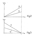
- each angular-position sensor 10 or 11 is a double potentiometer having two ratiometric and linear outputs in the range 0-5 V and in which a measurement V B and V D of the angular position ⁇ of the rotating shaft 4 is equal to half of the other measurement V A or V C of the angular position ⁇ of the rotating shaft 4.
- the measurements V A and V B supplied by the angular-position sensor 10 as a function of the angular position ⁇ of the rotating shaft 4 are illustrated in Figure 2 and the measurements V C and V D supplied by the angular-position sensor 11 as a function of the angular position ⁇ of the rotating shaft 4 are illustrated in Figure 3 .
- the two measurements V C and V D of the angular position ⁇ of the rotating shaft 4 of the angular-position sensor 11 follow a law different with respect to the two measurements V A and V B of the angular position ⁇ of the rotating shaft 4 of the angular-position sensor 10 so as to be able to highlight better any possible problems (for example, an electrical failure that determines a variation of the electrical potential of the electrical ground). Said situation is immediately evident by comparing the graph of Figure 2 for the angular-position sensor 10 and the graph of Figure 3 for the angular-position sensor 11.
- the measurements V A and V B of the angular position ⁇ of the rotating shaft 4 of the angular-position sensor 10 increase as the angular position ⁇ of the rotating shaft 4 increases, whilst the measurements V C and V D of the angular position ⁇ of the rotating shaft 4 of the angular-position sensor 11 decrease as the angular position ⁇ of the rotating shaft 4 increases, with a rate of variation equal and opposite to the rate of variation of the measurements V A and V B of the angular position ⁇ of the rotating shaft 4 of the angular-position sensor 10.
- the processing unit 14 uses the cross comparison between the four measurements V A , V B , V C and V D available for diagnosing any possible malfunctioning of the angular-position sensors 10 and 11.
- V C 2 * V D ⁇ Tolerance 1
- V A + V C K 1 ⁇ Tolerance 2
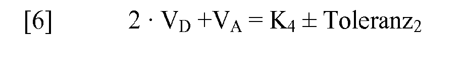
- K 1 , K 2 , K 3 and K 4 are verification constants linked to the constructional characteristics of the angular-position sensors 10 and 11, whilst Tolerance 1 and Tolerance 2 are predefined threshold values that take into account the inevitable errors of measurement committed by the angular-position sensors 10 and 11.
- the values of the verification constants K 1 , K 2 , K 3 and K 4 are not established a priori, but are determined during an initial calibration step of the acquisition system 1.
- the acquisition system 1 goes automatically into a calibration or self-learning condition, in which the tester must get the gas knob 2 to make some rotations with the engine turned off.
- the processing unit 14 determines the effective values of the verification constants K 1 , K 2 , K 3 and K 4 that it will use subsequently.
- the processing unit 14 determines a number of values for each verification constant K 1 , K 2 , K 3 and K 4 to be able to make a possibly weighted average (the last values measured may be more significant than the first values measured in so far as, during the first rotations of the gas knob 2 there may occur minor mechanical settling).
- the acquisition system 1 goes automatically into a calibration or self-learning condition.
- the processing unit 14 measures the effective angular position ⁇ of the rotating shaft 4 (i.e., of the gas knob 2) corresponding to the resting position (i.e., zero torque).
- the tester must not touch the gas knob 2 to enable the processing unit 14 to measure the effective angular position ⁇ of the rotating shaft 4 (i.e., of the gas knob 2) corresponding to the resting position (i.e., zero torque). In this way, it is possible to make up for all the constructional and assembly tolerances and moreover it is possible to verify that the assembly of the acquisition system 1 has been carried out properly.
- the processing unit 14 whenever the ignition key the processing unit 14 is turned, it measures the effective angular position ⁇ of the rotating shaft 4 (i.e., of the gas knob 2) corresponding to the resting position (i.e., zero torque) and inhibits engine ignition until the correctness of said measurement is verified, i.e., the correspondence of said measurement with an expected value.
- the processing unit 14 uses the cross comparison between the four measurements V A , V B , V C and V D available for diagnosing any possible malfunctioning of the angular-position sensors 10 and 11.
- the cross comparison between the four measurements V A , V B , V C and V D available envisages, for example, carrying out the verifications described in the equations [1]-[6] given above. If all the verifications are positive (i.e., if all the equations [1]-[6] are verified within the predefined tolerance margins), then the four measurements available of the angular position ⁇ of the rotating shaft 4 are all correct and equivalent. At this point, the processing unit 14 uses one of these four available measurements of the angular position ⁇ of the rotating shaft 4.
- the angular-position sensor 10 is considered as the main one and in conditions of normal operation one of the measurements (always the same) supplied by the main angular-position sensor 10 is used.
- the auxiliary or control angular-position sensor 11 could have a precision lower than that of the main angular-position sensor 10. Said choice does not limit the overall performance and reliability of the acquisition system 1, but only involves an increase of the predefined threshold values Tolerance 1 and Tolerance 2 present in the equations [1]-[6] given above.
- the processing unit 14 for determining the measurement of the angular position ⁇ of the rotating shaft 4 the processing unit 14 performs an arithmetic mean between the two measurements V A and V B supplied by the main angular-position sensor 10 (if the two angular-position sensors 10 and 11 have different precision), or else performs an arithmetic mean between the four measurements V A , V B , V C and V D supplied by the main angular-position sensors 10 and 11 (if the two angular-position sensors 10 and 11 have the same precision).
- the processing unit 14 identifies the potentiometer or potentiometers that has/have failed of the angular-position sensors 10 and 11 and excludes the measurement (or measurements) V A , V B , V C and V D corresponding to the potentiometer or potentiometers that has/have failed of the angular-position sensors 10 and 11.
- the processing unit 14 activates a condition of emergency (referred to also as recovery condition), in which the performance of the engine is limited in a way increasing as a function of the increase in the number of potentiometers failed of the angular-position sensors 10 and 11.
- recovery condition a condition of emergency
- the performance of the engine is slightly limited, enabling travel at a speed slightly lower than the nominal performance (for example, it is not possible to exceed 130km/h).
- the processing unit 14 determines that the equations [1], [3] and [6] are not verified whilst the equations [2], [4] and [5] are verified. Consequently, if the processing unit 14 determines that the equations [1], [3] and [6] are not verified whilst the equations [2], [4] and [5] are verified, then the processing unit 14 diagnoses a failure of the potentiometer of the angular-position sensor 10 that supplies the measurement V A and in no way uses the measurement V A for determining the angular position ⁇ of the rotating shaft 4 (i.e., of the gas knob 2).
- the processing unit 14 determines that the equations [1], [3]-[6] are not verified whilst only the equation [2] is verified, then the processing unit 14 diagnoses a failure of the angular-position sensor 10 and in no way uses the measurements V A and V B for determining the angular position ⁇ of the rotating shaft 4 (i.e., of the gas knob 2).
- the acquisition method described above presents numerous advantages in so far as it is simple and inexpensive to produce, is extremely flexible in so far as it can be easily installed on any type of motorcycle, and interfaces with a gas knob 2 of a traditional type, thus reducing the investments necessary for its implementation.
- the acquisition method described above enables maintenance of a gas knob 2 of a traditional type having a cable connection (well proven and reliable). Consequently, the supporting body 3 can be installed in a very protected area both with respect to possible falls or accidental bumps and with respect to atmospheric and environmental agents.
- the acquisition method described above guarantees a standard solution for a DBW motorcycle system and integrates in a single object all the functions of "gas demand" and all the redundancies required by safety.
- the acquisition method described above enables a precise and above all very reliable measurement of the angular position ⁇ of the rotating shaft 4 (i.e., of the gas knob 2) to be obtained, and even in the event of limited failure of the angular-position sensors 10 and 11 enables travel of the motorcycle in conditions of a high level of safety.
Landscapes
- Engineering & Computer Science (AREA)
- Mechanical Engineering (AREA)
- Chemical & Material Sciences (AREA)
- Combustion & Propulsion (AREA)
- General Engineering & Computer Science (AREA)
- Combined Controls Of Internal Combustion Engines (AREA)
- Control Of Throttle Valves Provided In The Intake System Or In The Exhaust System (AREA)
- Length Measuring Devices With Unspecified Measuring Means (AREA)
Claims (27)
- Ein Verfahren zum Erkennen der Winkelposition (α) eines Gasgriffs (2) eines Kraftrads, das die folgenden Schritte aufweist:gleichzeitiges Erkennen von vier gegenseitig redundanten Messungen (VA, VB, VC, VD) der Winkelposition (α) des Gasgriffs (2) mittels zweier gegenseitig unabhängiger Winkelpositionssensoren (10, 11), die Teil eines Erfassungssystems (1) sind,Durchführen eines zwei mit zwei Kreuzvergleichs zwischen den vier Messungen (VA, VB, VC, VD) zum Erkennen irgendeiner möglichen Fehlfunktion der Winkelpositionssensoren (10, 11) undBestimmen der Winkelposition (α) des Gasgriffs (2) durch Verwenden von mindestens einer Messung (VA, VB, VC, VD), die durch einen korrekt funktionierenden Winkelpositionssensor (10, 11) geliefert wird.
- Das Verfahren gemäß Anspruch 1, worin die Winkelposition (α) des Gasgriffs (2) als gleich mit einer einzelnen Messung angenommen wird, die durch einen korrekt funktionierenden Winkelpositionssensor (10, 11) geliefert wird.
- Das Verfahren gemäß Anspruch 1, worin die Winkelposition (α) des Gasgriffs (2) als gleich mit einem Mittelwert von mindestens zwei Messungen angenommen wird, die durch mindestens einen korrekt funktionierenden Winkelpositionssensor (10, 11) geliefert werden.
- Das Verfahren gemäß Anspruch 1, Anspruch 2 oder Anspruch 3, das den weiteren Schritt aufweist:Beschränken der Leistung eines Motors des Kraftrads im Fall des Versagens von mindestens einem Winkelpositionssensor (10, 11).
- Das Verfahren gemäß Anspruch 4, worin die Leistung des Motors in einer Weise beschränkt ist, die als eine Funktion der Zunahme in der Anzahl von Fehlmessungen (VA, VB, VC, VD) zunimmt.
- Das Verfahren gemäß Anspruch 4, worin:die Leistung des Motors im Fall von nur einer Fehlmessung (VA, VB, VC, VD) leicht beschränkt wird, was das Reisen mit einer niedrigeren Geschwindigkeit im Bezug auf die Nominalleistung erlaubt,die Leistung des Motors im Fall von zwei Fehlmessungen (VA, VB, VC, VD) beschränkt wird, was das Reisen mit einer viel niedrigeren Geschwindigkeit in Bezug auf die Nominalleistung erlaubt, unddie Leistung des Motors im Fall von drei Fehlmessungen (VA, VB, VC, VD) deutlich beschränkt wird, was den Betrieb nur bei einer konstanten Umdrehungszahl erlaubt.
- Das Verfahren gemäß einem der Ansprüche 1 bis 6, worin der zwei mit zwei Kreuzvergleich zwischen den vier falschen Messungen (VA, VB, VC, VD), die durch den Winkelpositionssensor (10, 11) geliefert werden, die Verifikation der folgenden Gleichungen vorsieht:


 VA, VB, VC, VD sind die vier Messungen, die durch den Winkelpositionssensor (10, 11) geliefert werden,K1, K2, K3, K4, sind vier Konstanten der Verifikation,Toleranz1 ist ein erster vordefinierter Grenzwert, der die Fehler der durch die Winkelpositionssensoren (10, 11) durchgeführten Messung berücksichtigt,Toleranz2 ist ein zweiter vordefinierter Grenzwert, der die Fehler der durch die Winkelpositionssensoren (10, 11) durchgeführten Messung berücksichtigt.
 - Das Verfahren gemäß Anspruch 7, das weiterhin den Schritt aufweist:Lernen der effektiven Werte der Verifikationskonstanten (K1, K2, K3, K4) während eines anfänglichen Kalibrationsschritts des Erfassungssystems (1).
- Das Verfahren gemäß Anspruch 8, worin bei der ersten Inbetriebnahme des Erfassungssystems (1) das Erfassungssystem (1) automatisch in einen Kalibrationszustand geht, in dem ein Tester den Gasgriff (2) bei abgeschaltetem Motor greifen muss, um einige Drehungen zum Bestimmen der effektiven Werte der Verifikationskonstanten (K1, K2, K3, K4) durchzuführen.
- Das Verfahren gemäß Anspruch 7, 8 oder 9, worin:beide der Winkelpositionssensoren (10, 11) korrekt funktionieren und alle vier Messungen (VA, VB, VC, VD), die durch den Winkelpositionssensor (10, 11) geliefert werden, korrekt sind, wenn alle sechs Gleichungen [1] - [6] innerhalb der vordefinierten Toleranzgrenzen verifiziert sind,ein Winkelpositionssensor (10, 11) teilweise versagt und eine der vier Messungen (VA, VB, VC, VD), die durch die Winkelpositionssensoren (10, 11) geliefert werden, falsch ist, wenn nur drei der sechs Gleichungen [1] - [6] innerhalb der vordefinierten Toleranzgrenzen verifiziert werden,mindestens ein Winkelpositionssensor (10, 11) teilweise versagt und zwei der vier Messungen (VA, VB, VC, VD), die durch die Winkelpositionssensoren (10, 11) geliefert werden, falsch sind, wenn nur eine der sechs Gleichungen [1] - [6] innerhalb der vordefinierten Toleranzgrenzen verifiziert wird,beide Winkelpositionssensoren (10, 11) mindestens teilweise versagen und mindestens drei der vier Messungen (VA, VB, VC, VD), die durch die Winkelpositionssensoren (10, 11) geliefert werden, falsch sind, wenn keine der sechs Gleichungen [1] - [6] innerhalb der vordefinierten Toleranzgrenzen verifiziert wird.
- Das Verfahren gemäß einem der Ansprüche 1 bis 10, worin bei der ersten Inbetriebnahme des Erfassungssystems (1) das Erfassungssystem (1) automatisch in einen Kalibrationszustand geht, in dem die effektive Winkelposition (α) des Gasgriffs (2) entsprechend zur Ruheposition gemessen wird.
- Das Verfahren gemäß einem der Ansprüche 1 bis 10, worin, jedes Mal wenn das Erfassungssystem (1) in Betrieb genommen wird, das Erfassungssystem (1) automatisch in einen Kalibrationszustand geht, in dem die effektive Winkelposition (α) des Gasgriffs (2) entsprechend zur Ruheposition gemessen wird.
- Das Verfahren gemäß Anspruch 11 oder Anspruch 12, worin das Einschalten des Motors des Kraftrads gehemmt ist, wenn die effektive Winkelposition (α) des Gasgriffs (2) entsprechend zur Ruheposition nicht einem erwarteten Wert entspricht.
- Das Verfahren gemäß einem der Ansprüche 1 bis 13, worin das Erfassungssystem (1) umfasst:einen festen Stützkörper (3),eine drehende Welle (4), die drehbar in dem Stützkörper (3) montiert ist und mechanisch an die zwei Winkelpositionssensoren (10, 11) gekoppelt ist, undeine Übertragungsvorrichtung (6), die mechanisch mit dem Gasgriff (2) und der drehenden Welle (4) verbunden ist, um die Bewegung des Gasgriffs (2) hin zu der drehenden Welle (4) selbst zu übertragen.
- Das Verfahren gemäß Anspruch 14, worin die Übertragungsvorrichtung (6) vom Kabeltyp ist und eine Seilscheibe (7) eines Zweirichtungstyps, die mit Bezug auf die drehenden Welle (4) fest ist, und ein Paar Bowdenzüge umfasst, von denen jeder ein Ende hat, das am Gasgriff (2) eingespannt ist, und ein entgegengesetztes Ende, das mit Bezug auf die Seilscheibe (7) fest ist.
- Das Verfahren gemäß Anspruch 14, worin die Übertragungsvorrichtung (6) vom Kabeltyp ist und eine Seilscheibe (7), die mit Bezug auf die drehende Welle (4) fest ist, und einen Bowdenzug umfasst, der ein Ende hat, das am Gasgriff (2) eingespannt ist, und ein entgegengesetztes Ende, das mit Bezug auf die Seilscheibe (7) fest ist.
- Das Verfahren gemäß Anspruch 14, worin die Übertragungsvorrichtung (6) eine direkte mechanische Verbindung zum koaxialen Übertragen auf die drehende Welle (4) umfasst und die winklig mit Bezug auf den Griff (2) befestigt ist.
- Das Verfahren gemäß einem der Ansprüche 1 bis 17, worin eine Rückstellfeder bereitgestellt ist, die um die drehende Welle (4) zum Drücken der drehenden Welle (4) selbst mit einer vorgegebenen Kraft in Richtung einer Ruheposition angeordnet ist, die einem Nulldrehmoment entspricht.
- Das Verfahren gemäß einem der Ansprüche 14 bis 18, worin zwei Winkelpositionssensoren (10, 11) an den entgegengesetzten Enden der drehenden Welle (4) angeordnet sind.
- Das Verfahren gemäß Anspruch 19, worin der feste Stützkörper (3) C-förmig ist und durch die drehende Welle (4) durchquert wird, die den festen Stützkörper (3) an zwei entgegengesetzten Enden der drehenden Welle (4) verlässt.
- Das Verfahren gemäß Anspruch 20, worin die Übertragungsvorrichtung (6) vom Kabeltyp ist und eine Seilscheibe (7), die mit Bezug auf die drehende Welle (4) fest ist und in einer mittigen Position der drehenden Welle (4) selbst angeordnet ist, und mindestens einen Bowdenzug umfasst, der ein Ende hat, das am Gasgriff (2) eingespannt ist, und ein entgegengesetztes Ende, das mit Bezug auf die Seilscheibe (7) fest ist.
- Das Verfahren gemäß einem der Ansprüche 1 bis 21, worin jeder Hauptwinkelpositionssensor (10, 11) ein Doppelpotentiometer ist.
- Das Verfahren gemäß Anspruch 22, worin für jeden Winkelpositionssensor (10, 11) eine Messung der Winkelposition (α) der drehenden Welle (4) gleich der Hälfte der anderen Messung der Winkelposition (α) der drehenden Welle (4) ist.
- Das Verfahren gemäß Anspruch 23, worin die zwei Messungen der Winkelposition (α) der drehenden Welle (4) eines ersten Winkelpositionssensors (10) einem anderen Gesetz folgen mit Bezug auf die zweite Messung der Winkelposition (α) der drehenden Welle (4) eines zweiten Winkelpositionssensors (11).
- Das Verfahren gemäß Anspruch 24, worin die Messungen (VA, VB) der Winkelposition (α) des Gasgriffs (2), die durch einen ersten Winkelpositionssensor (10) geliefert werden, zunehmen, wenn die Winkelposition (α) des Gasgriffs (2) zunimmt, während die Messungen (VC, VD) der Winkelposition (α) des Gasgriffs (2) von einem zweiten Winkelpositionssensor (11) mit einer Variationsrate gleich und entgegengesetzt zu der Variationsrate der Messungen (VA, VB) der Winkelposition (α) des Gasgriffs (2), die durch den ersten Winkelpositionssensor (10) geliefert werden, abnehmen, wenn die Winkelposition (α) des Gasgriffs (2) zunimmt.
- Das Verfahren gemäß einem der Ansprüche 1 bis 25, worin jeder Positionssensor (10; 11) mit einer Verarbeitungseinheit (14) des Erfassungssystems (1) mittels einer eigenen Verdrahtung (15) unabhängig vom anderen Winkelpositionssensor (11; 10) verbunden ist.
- Das Verfahren gemäß Anspruch 26, worin Verbinder der Verdrahtung (15) eines ersten Winkelpositionssensors (10) physikalisch verschieden von den Verbindern der Verdrahtung (15) eines zweiten Winkelpositionssensor (11) sind.
Priority Applications (11)
| Application Number | Priority Date | Filing Date | Title |
|---|---|---|---|
| DE602007000967T DE602007000967D1 (de) | 2007-06-04 | 2007-06-04 | Verfahren zur Erkennung der Winkelposition eines Gasgriffes eines Motorrads |
| AT07425345T ATE429379T1 (de) | 2007-06-04 | 2007-06-04 | Verfahren zur erkennung der winkelposition eines gasgriffes eines motorrads |
| EP07425345A EP2000397B1 (de) | 2007-06-04 | 2007-06-04 | Verfahren zur Erkennung der Winkelposition eines Gasgriffes eines Motorrads |
| BRPI0713234-4A BRPI0713234B1 (pt) | 2006-07-07 | 2007-07-06 | Sistema de aquisição para detectar a posição angular de um botão para o gás de uma motocicleta |
| CN2007800302419A CN101529066B (zh) | 2006-07-07 | 2007-07-06 | 用于设置有气门旋钮和用于检测摩托车的气门旋钮的角位置的采集系统的摩托车的内燃发动机的集成控制系统 |
| EP07804570.5A EP2041413B1 (de) | 2006-07-07 | 2007-07-06 | Vorrichtung zur erfassung der winkelposition eines gashandgriffs eines motorrades |
| US12/309,117 US8046151B2 (en) | 2006-07-07 | 2007-07-06 | Integrated control system for an internal-combustion engine of a motorcycle provided with a gas knob and acquisition system for detecting the angular position of a knob for the gas of a motorcycle |
| PCT/IB2007/001867 WO2008007193A2 (en) | 2006-07-07 | 2007-07-06 | Acquisition system for detecting the angular position of a knob for the gas of a motorcycle |
| US12/018,296 US7729849B2 (en) | 2007-06-04 | 2008-01-23 | Method for detecting the angular position of a knob for the gas of a motorcycle |
| BRPI0800061-1A BRPI0800061A2 (pt) | 2007-06-04 | 2008-01-28 | mÉtodo para detecÇço da posiÇço angular de uma manete para a aceleraÇço de uma motocicleta |
| CN2008100087758A CN101319871B (zh) | 2007-06-04 | 2008-01-29 | 用于检测摩托车的油门旋钮的角位置的方法 |
Applications Claiming Priority (1)
| Application Number | Priority Date | Filing Date | Title |
|---|---|---|---|
| EP07425345A EP2000397B1 (de) | 2007-06-04 | 2007-06-04 | Verfahren zur Erkennung der Winkelposition eines Gasgriffes eines Motorrads |
Publications (2)
| Publication Number | Publication Date |
|---|---|
| EP2000397A1 EP2000397A1 (de) | 2008-12-10 |
| EP2000397B1 true EP2000397B1 (de) | 2009-04-22 |
Family
ID=38626246
Family Applications (1)
| Application Number | Title | Priority Date | Filing Date |
|---|---|---|---|
| EP07425345A Not-in-force EP2000397B1 (de) | 2006-07-07 | 2007-06-04 | Verfahren zur Erkennung der Winkelposition eines Gasgriffes eines Motorrads |
Country Status (6)
| Country | Link |
|---|---|
| US (1) | US7729849B2 (de) |
| EP (1) | EP2000397B1 (de) |
| CN (1) | CN101319871B (de) |
| AT (1) | ATE429379T1 (de) |
| BR (1) | BRPI0800061A2 (de) |
| DE (1) | DE602007000967D1 (de) |
Families Citing this family (5)
| Publication number | Priority date | Publication date | Assignee | Title |
|---|---|---|---|---|
| US9528822B2 (en) * | 2013-02-08 | 2016-12-27 | Hunter Engineering Company | Calibration fixture for machine vision vehicle wheel alignment system |
| FR3063043B1 (fr) * | 2017-02-23 | 2019-03-15 | Continental Automotive France | Systeme de commande d'un vehicule muni de commandes electriques |
| WO2018205261A1 (en) * | 2017-05-12 | 2018-11-15 | Texas Instruments Incorporated | Methods and apparatus to determine a position of a rotatable shaft of a motor |
| JP7080280B2 (ja) * | 2020-07-27 | 2022-06-03 | 三菱電機株式会社 | 電動制動装置 |
| EP4123264A1 (de) * | 2021-07-21 | 2023-01-25 | Goodrich Actuation Systems Limited | Überfahrerkennungsvorrichtung |
Family Cites Families (9)
| Publication number | Priority date | Publication date | Assignee | Title |
|---|---|---|---|---|
| JP3770675B2 (ja) * | 1996-12-19 | 2006-04-26 | トヨタ自動車株式会社 | スロットル制御装置 |
| US5933005A (en) * | 1997-07-29 | 1999-08-03 | Brunswick Corporation | Throttle position monitor with one stationary sensor and one movable sensor |
| JP2003254115A (ja) * | 2002-02-26 | 2003-09-10 | Yamaha Motor Co Ltd | スロットル開度センサ |
| JP2004324720A (ja) * | 2003-04-23 | 2004-11-18 | Aisin Aw Co Ltd | 回転角度検出センサーの故障検出装置 |
| JP4287291B2 (ja) * | 2004-01-06 | 2009-07-01 | ヤマハ発動機株式会社 | 車両のスロットル装置 |
| US7188021B2 (en) * | 2004-10-25 | 2007-03-06 | Litens Automotive Partnership | Angular position sensor-based engine controller system |
| JP2006336638A (ja) * | 2005-05-02 | 2006-12-14 | Yamaha Motor Co Ltd | 鞍乗型車両 |
| US20070132449A1 (en) * | 2005-12-08 | 2007-06-14 | Madni Asad M | Multi-turn non-contact angular position sensor |
| ATE492717T1 (de) * | 2006-07-07 | 2011-01-15 | Magneti Marelli Spa | Vorrichtung zur erfassung der winkelposition eines gashandgriffs eines motorrades |
-
2007
- 2007-06-04 DE DE602007000967T patent/DE602007000967D1/de active Active
- 2007-06-04 EP EP07425345A patent/EP2000397B1/de not_active Not-in-force
- 2007-06-04 AT AT07425345T patent/ATE429379T1/de not_active IP Right Cessation
-
2008
- 2008-01-23 US US12/018,296 patent/US7729849B2/en not_active Expired - Fee Related
- 2008-01-28 BR BRPI0800061-1A patent/BRPI0800061A2/pt not_active IP Right Cessation
- 2008-01-29 CN CN2008100087758A patent/CN101319871B/zh not_active Expired - Fee Related
Also Published As
| Publication number | Publication date |
|---|---|
| EP2000397A1 (de) | 2008-12-10 |
| US20080295801A1 (en) | 2008-12-04 |
| ATE429379T1 (de) | 2009-05-15 |
| DE602007000967D1 (de) | 2009-06-04 |
| BRPI0800061A2 (pt) | 2009-01-27 |
| CN101319871B (zh) | 2012-08-22 |
| CN101319871A (zh) | 2008-12-10 |
| US7729849B2 (en) | 2010-06-01 |
Similar Documents
| Publication | Publication Date | Title |
|---|---|---|
| US7571073B2 (en) | Acquisition system for detecting the angular position of a gas twist grip in a motorcycle | |
| US8660746B2 (en) | Accelerator pedal apparatus | |
| EP2000397B1 (de) | Verfahren zur Erkennung der Winkelposition eines Gasgriffes eines Motorrads | |
| CN110733562B (zh) | 用于控制线控转向系统的设备和方法 | |
| EP0555892B1 (de) | Steuerungssystem der Drosselklappe einer Brennkraftmaschine | |
| US7743875B2 (en) | Power steering apparatus having failure detection device for rotation angle sensors | |
| US8428822B2 (en) | Method of determining a steering angle in a motor vehicle | |
| EP3103989B1 (de) | Steuerungsbordvorrichtung | |
| CN109196208B (zh) | 驱动力控制系统的异常诊断方法以及异常诊断装置 | |
| US6397152B1 (en) | Method and motor control apparatus for the correction of a computer-established torque in the drive train of a motor vehicle | |
| CN113532249B (zh) | 用于转向柱的绝对位置非接触式倾斜传感器 | |
| JP3463463B2 (ja) | センサの異常診断装置 | |
| EP2041413B1 (de) | Vorrichtung zur erfassung der winkelposition eines gashandgriffs eines motorrades | |
| JP2009062998A (ja) | 車両制御システム | |
| JP4229284B2 (ja) | 内燃機関の電子スロットル制御装置 | |
| WO2006114678A1 (en) | Vehicle integrated-control apparatus and vehicle integrated-control method | |
| CN2828754Y (zh) | 非接触式汽机车角度传感器 | |
| KR100836296B1 (ko) | 차량의 쉬프트 포지션 센서 고장 처리 방법 | |
| JP4609948B2 (ja) | 自動車のアクセルペダルの踏み込み信号発生装置の故障検出方法 | |
| JP2010133276A (ja) | スロットル装置およびそれを備えた輸送機器 | |
| JP2006228002A (ja) | 故障検知機能付き二重系システム | |
| KR100335930B1 (ko) | 캔 통신에 의한 엔진 토크 표시 방법 | |
| JP2012207705A (ja) | 自動変速装置 | |
| KR100716921B1 (ko) | 가속페달 센서의 고장 진단 방법 | |
| KR20050068640A (ko) | 스로틀포지션센서 고장진단 방법 |
Legal Events
| Date | Code | Title | Description |
|---|---|---|---|
| GRAP | Despatch of communication of intention to grant a patent |
Free format text: ORIGINAL CODE: EPIDOSNIGR1 |
|
| PUAI | Public reference made under article 153(3) epc to a published international application that has entered the european phase |
Free format text: ORIGINAL CODE: 0009012 |
|
| 17P | Request for examination filed |
Effective date: 20080207 |
|
| AK | Designated contracting states |
Kind code of ref document: A1 Designated state(s): AT BE BG CH CY CZ DE DK EE ES FI FR GB GR HU IE IS IT LI LT LU LV MC MT NL PL PT RO SE SI SK TR |
|
| AX | Request for extension of the european patent |
Extension state: AL BA HR MK RS |
|
| GRAS | Grant fee paid |
Free format text: ORIGINAL CODE: EPIDOSNIGR3 |
|
| RAP1 | Party data changed (applicant data changed or rights of an application transferred) |
Owner name: MAGNETI MARELLI HOLDING S.P.A. |
|
| RAP1 | Party data changed (applicant data changed or rights of an application transferred) |
Owner name: MAGNETI MARELLI S.P.A. |
|
| GRAA | (expected) grant |
Free format text: ORIGINAL CODE: 0009210 |
|
| AK | Designated contracting states |
Kind code of ref document: B1 Designated state(s): AT BE BG CH CY CZ DE DK EE ES FI FR GB GR HU IE IS IT LI LT LU LV MC MT NL PL PT RO SE SI SK TR |
|
| REG | Reference to a national code |
Ref country code: GB Ref legal event code: FG4D |
|
| REG | Reference to a national code |
Ref country code: CH Ref legal event code: EP |
|
| REG | Reference to a national code |
Ref country code: IE Ref legal event code: FG4D |
|
| REF | Corresponds to: |
Ref document number: 602007000967 Country of ref document: DE Date of ref document: 20090604 Kind code of ref document: P |
|
| AKX | Designation fees paid |
Designated state(s): AT BE BG CH CY CZ DE DK EE ES FI FR GB GR HU IE IS IT LI LT LU LV MC MT NL PL PT RO SE SI SK TR |
|
| NLV1 | Nl: lapsed or annulled due to failure to fulfill the requirements of art. 29p and 29m of the patents act | ||
| PG25 | Lapsed in a contracting state [announced via postgrant information from national office to epo] |
Ref country code: ES Free format text: LAPSE BECAUSE OF FAILURE TO SUBMIT A TRANSLATION OF THE DESCRIPTION OR TO PAY THE FEE WITHIN THE PRESCRIBED TIME-LIMIT Effective date: 20090802 Ref country code: LT Free format text: LAPSE BECAUSE OF FAILURE TO SUBMIT A TRANSLATION OF THE DESCRIPTION OR TO PAY THE FEE WITHIN THE PRESCRIBED TIME-LIMIT Effective date: 20090422 Ref country code: FI Free format text: LAPSE BECAUSE OF FAILURE TO SUBMIT A TRANSLATION OF THE DESCRIPTION OR TO PAY THE FEE WITHIN THE PRESCRIBED TIME-LIMIT Effective date: 20090422 Ref country code: AT Free format text: LAPSE BECAUSE OF FAILURE TO SUBMIT A TRANSLATION OF THE DESCRIPTION OR TO PAY THE FEE WITHIN THE PRESCRIBED TIME-LIMIT Effective date: 20090422 Ref country code: PT Free format text: LAPSE BECAUSE OF FAILURE TO SUBMIT A TRANSLATION OF THE DESCRIPTION OR TO PAY THE FEE WITHIN THE PRESCRIBED TIME-LIMIT Effective date: 20090822 |
|
| PG25 | Lapsed in a contracting state [announced via postgrant information from national office to epo] |
Ref country code: IS Free format text: LAPSE BECAUSE OF FAILURE TO SUBMIT A TRANSLATION OF THE DESCRIPTION OR TO PAY THE FEE WITHIN THE PRESCRIBED TIME-LIMIT Effective date: 20090822 Ref country code: NL Free format text: LAPSE BECAUSE OF FAILURE TO SUBMIT A TRANSLATION OF THE DESCRIPTION OR TO PAY THE FEE WITHIN THE PRESCRIBED TIME-LIMIT Effective date: 20090422 Ref country code: SI Free format text: LAPSE BECAUSE OF FAILURE TO SUBMIT A TRANSLATION OF THE DESCRIPTION OR TO PAY THE FEE WITHIN THE PRESCRIBED TIME-LIMIT Effective date: 20090422 Ref country code: PL Free format text: LAPSE BECAUSE OF FAILURE TO SUBMIT A TRANSLATION OF THE DESCRIPTION OR TO PAY THE FEE WITHIN THE PRESCRIBED TIME-LIMIT Effective date: 20090422 Ref country code: SE Free format text: LAPSE BECAUSE OF FAILURE TO SUBMIT A TRANSLATION OF THE DESCRIPTION OR TO PAY THE FEE WITHIN THE PRESCRIBED TIME-LIMIT Effective date: 20090722 Ref country code: LV Free format text: LAPSE BECAUSE OF FAILURE TO SUBMIT A TRANSLATION OF THE DESCRIPTION OR TO PAY THE FEE WITHIN THE PRESCRIBED TIME-LIMIT Effective date: 20090422 |
|
| PG25 | Lapsed in a contracting state [announced via postgrant information from national office to epo] |
Ref country code: RO Free format text: LAPSE BECAUSE OF FAILURE TO SUBMIT A TRANSLATION OF THE DESCRIPTION OR TO PAY THE FEE WITHIN THE PRESCRIBED TIME-LIMIT Effective date: 20090422 Ref country code: CZ Free format text: LAPSE BECAUSE OF FAILURE TO SUBMIT A TRANSLATION OF THE DESCRIPTION OR TO PAY THE FEE WITHIN THE PRESCRIBED TIME-LIMIT Effective date: 20090422 Ref country code: DK Free format text: LAPSE BECAUSE OF FAILURE TO SUBMIT A TRANSLATION OF THE DESCRIPTION OR TO PAY THE FEE WITHIN THE PRESCRIBED TIME-LIMIT Effective date: 20090422 Ref country code: MC Free format text: LAPSE BECAUSE OF NON-PAYMENT OF DUE FEES Effective date: 20090630 Ref country code: EE Free format text: LAPSE BECAUSE OF FAILURE TO SUBMIT A TRANSLATION OF THE DESCRIPTION OR TO PAY THE FEE WITHIN THE PRESCRIBED TIME-LIMIT Effective date: 20090422 |
|
| PG25 | Lapsed in a contracting state [announced via postgrant information from national office to epo] |
Ref country code: SK Free format text: LAPSE BECAUSE OF FAILURE TO SUBMIT A TRANSLATION OF THE DESCRIPTION OR TO PAY THE FEE WITHIN THE PRESCRIBED TIME-LIMIT Effective date: 20090422 Ref country code: BE Free format text: LAPSE BECAUSE OF FAILURE TO SUBMIT A TRANSLATION OF THE DESCRIPTION OR TO PAY THE FEE WITHIN THE PRESCRIBED TIME-LIMIT Effective date: 20090422 |
|
| PLBE | No opposition filed within time limit |
Free format text: ORIGINAL CODE: 0009261 |
|
| STAA | Information on the status of an ep patent application or granted ep patent |
Free format text: STATUS: NO OPPOSITION FILED WITHIN TIME LIMIT |
|
| 26N | No opposition filed |
Effective date: 20100125 |
|
| PG25 | Lapsed in a contracting state [announced via postgrant information from national office to epo] |
Ref country code: BG Free format text: LAPSE BECAUSE OF FAILURE TO SUBMIT A TRANSLATION OF THE DESCRIPTION OR TO PAY THE FEE WITHIN THE PRESCRIBED TIME-LIMIT Effective date: 20090722 |
|
| REG | Reference to a national code |
Ref country code: IE Ref legal event code: MM4A |
|
| PG25 | Lapsed in a contracting state [announced via postgrant information from national office to epo] |
Ref country code: IE Free format text: LAPSE BECAUSE OF NON-PAYMENT OF DUE FEES Effective date: 20090604 |
|
| PG25 | Lapsed in a contracting state [announced via postgrant information from national office to epo] |
Ref country code: GR Free format text: LAPSE BECAUSE OF FAILURE TO SUBMIT A TRANSLATION OF THE DESCRIPTION OR TO PAY THE FEE WITHIN THE PRESCRIBED TIME-LIMIT Effective date: 20090723 |
|
| PG25 | Lapsed in a contracting state [announced via postgrant information from national office to epo] |
Ref country code: LU Free format text: LAPSE BECAUSE OF NON-PAYMENT OF DUE FEES Effective date: 20090604 Ref country code: MT Free format text: LAPSE BECAUSE OF FAILURE TO SUBMIT A TRANSLATION OF THE DESCRIPTION OR TO PAY THE FEE WITHIN THE PRESCRIBED TIME-LIMIT Effective date: 20090422 |
|
| PG25 | Lapsed in a contracting state [announced via postgrant information from national office to epo] |
Ref country code: HU Free format text: LAPSE BECAUSE OF FAILURE TO SUBMIT A TRANSLATION OF THE DESCRIPTION OR TO PAY THE FEE WITHIN THE PRESCRIBED TIME-LIMIT Effective date: 20091023 |
|
| PG25 | Lapsed in a contracting state [announced via postgrant information from national office to epo] |
Ref country code: TR Free format text: LAPSE BECAUSE OF FAILURE TO SUBMIT A TRANSLATION OF THE DESCRIPTION OR TO PAY THE FEE WITHIN THE PRESCRIBED TIME-LIMIT Effective date: 20090422 |
|
| PG25 | Lapsed in a contracting state [announced via postgrant information from national office to epo] |
Ref country code: CY Free format text: LAPSE BECAUSE OF FAILURE TO SUBMIT A TRANSLATION OF THE DESCRIPTION OR TO PAY THE FEE WITHIN THE PRESCRIBED TIME-LIMIT Effective date: 20090422 |
|
| REG | Reference to a national code |
Ref country code: CH Ref legal event code: PL |
|
| GBPC | Gb: european patent ceased through non-payment of renewal fee |
Effective date: 20110604 |
|
| PG25 | Lapsed in a contracting state [announced via postgrant information from national office to epo] |
Ref country code: CH Free format text: LAPSE BECAUSE OF NON-PAYMENT OF DUE FEES Effective date: 20110630 Ref country code: LI Free format text: LAPSE BECAUSE OF NON-PAYMENT OF DUE FEES Effective date: 20110630 |
|
| PG25 | Lapsed in a contracting state [announced via postgrant information from national office to epo] |
Ref country code: GB Free format text: LAPSE BECAUSE OF NON-PAYMENT OF DUE FEES Effective date: 20110604 |
|
| REG | Reference to a national code |
Ref country code: FR Ref legal event code: PLFP Year of fee payment: 9 |
|
| PGFP | Annual fee paid to national office [announced via postgrant information from national office to epo] |
Ref country code: DE Payment date: 20150521 Year of fee payment: 9 |
|
| PGFP | Annual fee paid to national office [announced via postgrant information from national office to epo] |
Ref country code: IT Payment date: 20150529 Year of fee payment: 9 Ref country code: FR Payment date: 20150526 Year of fee payment: 9 |
|
| REG | Reference to a national code |
Ref country code: DE Ref legal event code: R119 Ref document number: 602007000967 Country of ref document: DE |
|
| REG | Reference to a national code |
Ref country code: FR Ref legal event code: ST Effective date: 20170228 |
|
| PG25 | Lapsed in a contracting state [announced via postgrant information from national office to epo] |
Ref country code: FR Free format text: LAPSE BECAUSE OF NON-PAYMENT OF DUE FEES Effective date: 20160630 Ref country code: DE Free format text: LAPSE BECAUSE OF NON-PAYMENT OF DUE FEES Effective date: 20170103 |
|
| PG25 | Lapsed in a contracting state [announced via postgrant information from national office to epo] |
Ref country code: IT Free format text: LAPSE BECAUSE OF NON-PAYMENT OF DUE FEES Effective date: 20160604 |