EP2000353B1 - Hoch- und runterklappbarer liegesitz zur verwendung in autos - Google Patents
Hoch- und runterklappbarer liegesitz zur verwendung in autos Download PDFInfo
- Publication number
- EP2000353B1 EP2000353B1 EP06843781A EP06843781A EP2000353B1 EP 2000353 B1 EP2000353 B1 EP 2000353B1 EP 06843781 A EP06843781 A EP 06843781A EP 06843781 A EP06843781 A EP 06843781A EP 2000353 B1 EP2000353 B1 EP 2000353B1
- Authority
- EP
- European Patent Office
- Prior art keywords
- latch
- seat
- seat cushion
- link
- spaced apart
- Prior art date
- Legal status (The legal status is an assumption and is not a legal conclusion. Google has not performed a legal analysis and makes no representation as to the accuracy of the status listed.)
- Not-in-force
Links
- 230000007246 mechanism Effects 0.000 claims abstract description 55
- 230000006698 induction Effects 0.000 claims description 63
- 230000005484 gravity Effects 0.000 claims description 25
- 230000009471 action Effects 0.000 claims description 10
- 230000000717 retained effect Effects 0.000 claims description 8
- 230000001154 acute effect Effects 0.000 claims description 5
- 230000008878 coupling Effects 0.000 description 1
- 238000010168 coupling process Methods 0.000 description 1
- 238000005859 coupling reaction Methods 0.000 description 1
- 230000014509 gene expression Effects 0.000 description 1
- 230000004048 modification Effects 0.000 description 1
- 238000012986 modification Methods 0.000 description 1
Images


Classifications
-
- B—PERFORMING OPERATIONS; TRANSPORTING
- B60—VEHICLES IN GENERAL
- B60N—SEATS SPECIALLY ADAPTED FOR VEHICLES; VEHICLE PASSENGER ACCOMMODATION NOT OTHERWISE PROVIDED FOR
- B60N2/00—Seats specially adapted for vehicles; Arrangement or mounting of seats in vehicles
- B60N2/24—Seats specially adapted for vehicles; Arrangement or mounting of seats in vehicles for particular purposes or particular vehicles
- B60N2/30—Non-dismountable or dismountable seats storable in a non-use position, e.g. foldable spare seats
- B60N2/3002—Non-dismountable or dismountable seats storable in a non-use position, e.g. foldable spare seats back-rest movements
- B60N2/3004—Non-dismountable or dismountable seats storable in a non-use position, e.g. foldable spare seats back-rest movements by rotation only
- B60N2/3009—Non-dismountable or dismountable seats storable in a non-use position, e.g. foldable spare seats back-rest movements by rotation only about transversal axis
- B60N2/3013—Non-dismountable or dismountable seats storable in a non-use position, e.g. foldable spare seats back-rest movements by rotation only about transversal axis the back-rest being hinged on the vehicle frame
-
- B—PERFORMING OPERATIONS; TRANSPORTING
- B60—VEHICLES IN GENERAL
- B60N—SEATS SPECIALLY ADAPTED FOR VEHICLES; VEHICLE PASSENGER ACCOMMODATION NOT OTHERWISE PROVIDED FOR
- B60N2/00—Seats specially adapted for vehicles; Arrangement or mounting of seats in vehicles
- B60N2/24—Seats specially adapted for vehicles; Arrangement or mounting of seats in vehicles for particular purposes or particular vehicles
- B60N2/30—Non-dismountable or dismountable seats storable in a non-use position, e.g. foldable spare seats
- B60N2/3038—Cushion movements
- B60N2/3063—Cushion movements by composed movement
- B60N2/3065—Cushion movements by composed movement in a longitudinal-vertical plane
Definitions
- the present invention relates to a tip-up/dive-down type reclining seat for a vehicle, which includes a seat back adapted to be pivoted forward and rearward and a seat cushion adapted to be tipped up.
- the vehicle seat is provided with reclining lock means for releasably locking the seat back so as to prevent the pivotal movement of the seat back and for allowing an angle of the seat back to be adjusted, and tipping-up lock means for releasably locking the seat cushion so as to prevent the tipping-up movement of the seat cushion, and is adapted to be dived down and then stored in a space on a lower step portion of a vehicle body floor.
- a tip-up/dive-down type seat for a vehicle which includes a seat back, a seat cushion capable of being tipped up to the seat back in a substantially vertical posture and tipping-up lock means for releasably locking the seat cushion
- Japanese Patent Application Laid-Open Publication No. 2005-212554 Japanese Patent Application Laid-Open Publication No. 2005-212554 .
- the entire seat can be dived down in a condition where the seat cushion is tipped up and the tipping-up lock means is maintained in a locked-state, and then stored in a space on a lower step portion of a vehicle body floor.
- the entire seat can be returned to a used position from the dived down position in a condition where the tipping-up lock means is maintained in an unlocked-state.
- the tip-up/dive-down type vehicle seat is not provided with reclining lock means for releasably locking the seat back, which can cause the seat back to be maintained in a substantially vertical posture, allow the seat back to be angularly adjusted and allow the seat back to be brought into a condition where it is allowed to be pivoted forward and releasably locked.
- the seat back is provided at one side thereof with a latch.
- the latch is engaged with a striker lock mounted to a side panel of a vehicle body, whereby the seat back is maintained in the substantially vertical posture.
- the seat cushion can be tipped up to the seat back maintained in the substantially vertical posture.
- a further tip-up/ drive-down type vehicle seat substantially corresponding to the one defined in the preamble of claim 1 is known, for example, from DE 103 55 819 A1 .
- a tip-up/dive-down type reclining seat for a vehicle having the features set forth in claim 1, the vehicle including a vehicle body floor having an upper step portion and a lower step portion.
- the tip-up/dive-down type reclining seat comprises a seat back including a pair of first spaced apart side brackets, a seat cushion including a pair of second spaced apart side brackets, a pair of third spaced apart base brackets mounted on the upper step portion, reclining lock means for releasably locking the seat back, the reclining lock means including a pair of reclining lock mechanisms each provided between a lower end portion of corresponding one of the first spaced apart side brackets and corresponding one of the third spaced apart base brackets, so that when the reclining lock mechanisms are locked, the seat back can be locked in a substantially vertical posture, and when the reclining lock mechanisms are unlocked, the seat back is allowed to be pivoted forward and rearward and angularly adjusted, the reclining lock mechanisms including actuating shafts coupled
- An entire vehicle seat in a condition where the seat cushion is located at the tipped-up position or in a condition where the seat back is pivoted forward with respect to the seat cushion in the used position can be dived down and stored in a space on the lower step portion of the vehicle body floor.
- a stopper pin is provided at the at least one of the second spaced apart side brackets so as to be arranged upward of corresponding one of the first support pins
- the first releasing means includes a collapsible link bar member coupled at a lower end portion thereof to corresponding one of the actuating shafts of the reclining lock mechanisms, a braking link having a laterally projecting induction pin provided at an upper end thereof and swingably supported at a middle portion thereof to an upper end portion of the collapsible link bar member by a second support pin, the braking link being adapted to be stoppingly engaged with the stopper pin from a downward direction, a first link plate swingably supported at a rearward portion thereof to the at least one of the first spaced apart side brackets by a third support pin and having a circular arc-shaped guide hole extending around the second support pin of the braking link, the induction pin of the braking link being inserted through the guide hole of the first link plate, and a first operating lever coupled to a forward portion
- the braking link is stoppingly abutted at the lower end portion thereof against the stopper pin and the induction pin of the braking link is located at the rear end portion of the guide hole formed in the first link plate, so that the used position of the entire vehicle seat is determined.
- the first link plate When the entire vehicle seat is located at the used position thereof and the first operating lever is pull-operated, the first link plate is swung up around the third support pin and the cam member is also swung up together with the swinging-up of the first link plate in such a manner that the lower portion of the cam member is disengaged from the engaging step portion of the latch and slips into the recess portion having the depth which is not less than the engaging region between the projecting tooth of the latch and each of the cutout teeth of the at least one of the second spaced apart side brackets, whereby the latch is swung up in such a manner that the projecting tooth of the latch is disengaged from any one of the cutout teeth and the seat cushion is brought to a condition where the seat cushion is allowed to be tipped up toward the seat back in the substantially vertical posture.
- the second link plate, the cam member and the latch come down by gravity and the lower portion of the cam member is engagingly abutted against the engaging step portion of the latch, whereby engagement of the projecting tooth of the latch and any one of the cutout teeth of the at least one of the second side brackets is maintained.
- the seat cushion is maintained in the tipped-up posture by the tipping-up lock means.
- the tipping-up lock means is unlocked as discussed above.
- the seat cushion is brought to the condition where it is allowed to be pivoted toward the used position thereof.
- the first link plate In a condition where the entire vehicle seat is located at the used position thereof and the reclining lock means and the tipping-up lock means are locked, when the first operating lever is pull-operated, the first link plate is swung up around the third support pin. At this time, the induction pin of the braking link is located at the rearward end of the guide hole formed in the first link plate and abutted against the middle hole edge region of the opening hole formed in the second link plate, the second link plate is also swung up synchronously with the swinging-up of the first link plate.
- the seat back In the condition where the reclining lock means and the tipping-up lock means are unlocked, the seat back can be angularly adjusted rearward.
- the first operating lever is released from the pulled-condition after the seat back is angularly adjusted rearward, the first link plate, the braking link, the link bar member, second link plate, the cam member, and the latch come down by gravity.
- the entire vehicle seat is maintained in the used position thereof.
- the seat back is pivoted forward and the entire vehicle seat can be then dived down and stored in the space on the lower step portion of the vehicle body floor.
- the first link plate, the braking link, the link bar member, the second link plate, the cam member and the latch cannot come down by gravity during the forward pivotal movement of the seat back, so that the reclining lock means and the tipping-up lock means are maintained in the locked-states.
- a person causes the seat back to be pivoted forward by a certain extent while holding the seat back with his/her hand, removes his/her hand from the seat back to the seat cushion and can lift the seat cushion down in the space on the lower step portion of the vehicle body floor.
- the reclining lock means and the tipping-up lock means are unlocked, so that the person can cause the entire vehicle seat to be easily returned to the used position thereof by lifting up the entire vehicle seat while holding the seat back with his/her hand.
- the stopper pin provided at the at least one of the second side brackets is separated from the lower end portion of the braking link and the induction pin of the braking link comes down by gravity and located at the forward end portion of the guide hole formed in the first link plate.
- the tipping-up lock means is maintained in the locked-state, since the second link plate has the opening hole which allows the induction pin of the braking link to be escapingly moved when the seat cushion is located at the tipped-up position and the reclining lock means is unlocked, and the second link plate is not swung up.
- the tipping-up lock means is maintained in the locked-state, so that the seat cushion is not pivoted with respect to the seat back and can be dived down together with the seat back and the entire vehicle seat can be then stored in the space on the lower step portion of the vehicle body floor.
- the person causes the seat back to be pivoted forward by a certain extent while holding the seat back with his/her hand, causes his/her hand to be removed from the seat back to the seat cushion and can lift the seat cushion down in the space on the lower step portion of the vehicle body floor, as discussed above.
- an angle of the cam member with respect to the latch is set in such a manner that an angle between a reference line connecting an axial center of the fourth support pin of the latch and an abutment point of the cam member against the engaging step portion of the latch, and a line connecting an axial center of the second support pin of the cam member and the abutment point is kept to be an acute angle, so that engagement between the projecting tooth of the latch and any one of the first and second cutout teeth can be maintained by the angle of the cam member relative to the latch.
- the angle of the cam member with respect to the latch is set in such a manner that the angle between the reference line connecting the axial center of the fourth support pin of the latch and the abutment point of the cam member against the engaging step portion of the latch, and the line connecting the axial center of the second support pin of the cam member and the abutment point is kept to be the acute angle, so that the cam functions as a prop with respect to the engaging step portion of the latch and the latch is held by the cam member so as to be unable to swing. Therefore, even if the person unintentionally tries to cause the seat cushion to be pivoted upward, the engagement between the projecting tooth of the latch and each of the cutout teeth of the at least one of the second side brackets is ensured.
- the lower portion of the cam member is formed into a substantially semielliptical shape
- the engaging step portion of the latch is formed so as to have a substantially J-shape which allows the lower portion of the cam member to be easily abutted against the engaging step portion of the latch
- the recess portion of the latch is formed so as to have a substantially U-shape which has a depth larger than the height of the engaged region between the projecting tooth and each of the cutout teeth and fits the lower portion of the cam member.
- the lower portion of the cam member is formed into the substantially semielliptical shape
- a bottom surface of the engaging step portion of the latch is formed so as to have the substantially J-shape which allows the lower portion of the cam member to be easily abutted against the engaging step portion of the latch
- the recess portion of the latch is formed so as to have the substantially U-shape which has the depth larger than the height of the engaged region between the projecting tooth and each of the cutout teeth and fits the lower portion of the cam member.
- the cam member when the second operating lever is pull-operated, the cam member is swung up in such a manner that the lower portion of said cam member is disengaged from the engaging step portion of the latch and slips into the recess portion of the latch, whereby the latch is considerably swung up, so that the projecting tooth of the latch can be positively disengaged from each of the cutout teeth of the at least one of the second side brackets.
- the stand leg portion is typically urged toward a stored position under the seat cushion by a spring which is retained at one end thereof to an upper end region of the stand leg portion and retained at the other end thereof to the at least one of the second spaced apart side brackets and the vehicle seat further includes a third wire cable which is coupled at one end portion of a wire thereof to the upper end region of the stand leg portion and coupled at the other end portion of said wire of said third wire cable to the seat back, so that when the tipping-up lock means is unlocked and the seat cushion is tipped up, said wire of the third wire cable is pushed so as to overcome an action of the spring and allow the stand leg portion to be pivoted toward a developed position and as the seat cushion is pivoted toward the tipped-up position, the action of the spring is exerted on the third wire cable.
- the stand leg portion 6 can be pivoted toward the stored position synchronously with the tipping-up movement of the seat cushion and diving-down movement of the entire vehicle seat, and can be pivoted toward the developed position synchronously with returning of the entire seat toward the used position of the entire vehicle seat or returning of the seat cushion toward the first used position.
- a tip-up/dive-down type reclining seat for a vehicle, the vehicle including a vehicle body floor having an upper step portion and a lower step portion.
- the tip-up/dive-down type reclining seat comprises a seat back including a pair of first spaced apart side brackets, a seat cushion including a pair of second spaced apart side brackets, a pair of third spaced apart base brackets mounted on the upper step portion, reclining lock means for releasably locking the seat back, the reclining lock means including a pair of reclining lock mechanisms each provided between a lower end portion of corresponding one of the first spaced apart side brackets and corresponding one of the third spaced apart base brackets, so that when the reclining lock mechanisms are locked, the seat back can be locked in a substantially vertical posture, and when the reclining lock mechanism are unlocked, the seat back is allowed to be pivoted forward and rearward and angularly adjusted, the reclining lock mechanisms including actuating shafts coupled to each other through
- a stopper pin is provided at the at least one of the second spaced apart side brackets so as to be arranged upward of corresponding one of the first support pins
- the first releasing means includes a collapsible link bar member coupled at a lower end portion thereof to corresponding one of the actuating shafts of the reclining lock mechanisms, a first braking link having a laterally projecting induction pin provided at an upper end thereof and swingably supported at a middle portion thereof to an upper end portion of the collapsible link bar member by a second support pin, the first braking link being adapted to be stoppingly at a lower portion thereof abutted the stopper pin from a downward direction, a first link plate swingably supported at a rearward portion thereof to the at least one of the first spaced apart side brackets by a third support pin and having a circular arc-shaped guide hole extending around the second support pin of the braking link and a substantially L-shaped control hole, the induction pin of the braking link being inserted through the guide
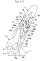
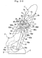
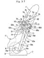
- the vehicle seat includes a seat back 1 adapted to be pivoted forward and rearward and having a pair of spaced apart side brackets serving as side frame sections of a seat back frame for the seat back 1, a seat cushion 5 pivotally supported to the seat back 1 so as to be capable of being tipped up, reclining lock means including first and second reclining lock mechanisms for releasably locking the seat back 1 and preventing the pivotal movement of the seat back 1 (only first reclining lock mechanism 3 is shown in Fig.
- first and second reclining lock mechanisms being constructed in the same manner, first releasing means for unlocking the first and second reclining lock mechanisms 3 and allowing the seat back to be brought to a condition where the seat back is allowed to be pivoted forward and rearward, tipping-up lock means for releasably locking the seat cushion 5 and preventing the tipping-up movement of the seat cushion, and second releasing means for unlocking the tipping-up means and allowing the seat cushion to be brought to a condition where the seat cushion is allowed to be tipped up.
- the reclining lock mechanisms 3 are provided between lower end portions of the spaced apart side brackets of the seat back 1 and a pair of spaced apart base brackets 2 mounted on an upper step portion f 1 of a vehicle body floor F so as to stand up from the upper step portion f1, so that the seat back 1 is allowed to be releasably locked with respect to the vehicle body floor F by the reclining lock mechanisms 3.
- reclining lock mechanisms 3 there may be employed reclining lock mechanisms which have actuating shafts 4 coupled to each other through a connecting shaft (not shown) which is connected at both ends thereof to the actuating shafts 4, whereby the reclining lock mechanisms are adapted to be synchronously actuated and can carry out unlocking operation by rotation of the actuating shafts 4 and locking operation by rotating-back of the actuating shafts 4 (refer to, for example, Japanese Patent Application Laid-Open No. 2004-173922 ).
- the seat cushion 5 includes a pair of spaced apart side brackets serving as side frame sections of a seat cushion frame for the seat cushion 5.
- the spaced apart side brackets of the seat cushion 5 are coupled at rear end portions thereof to portions of the side brackets of the seat back 1, which are adjacent the lower end portions of the spaced apart side brackets of the seat back 1, by support pins 50, so that the seat cushion 5 is pivotally supported to the seat back 1 so as to be allowed to be tipped up.
- the vehicle seat further includes a substantially U-shaped stand leg portion 6 in outline which is pivotally connected at upper end regions of spaced apart vertical portions thereof to lower regions of forward portions of the side brackets of the seat cushion 5 by support pins 6a.
- a receiving base 6b for receiving and engaging a lower horizontal portion of the stand leg portion 6 is mounted on a lower step portion f 2 of the vehicle body floor F.
- the stand leg portion 6 is adapted to be releasably engaged at the lower horizontal portion thereof with the receiving base 6b so as to obliquely stand up from the lower step portion f 2 of the vehicle body floor F, whereby when the seat cushion is located at a first used position at which the seat cushion 5 takes a substantially horizontal posture, the seat cushion 5 is horizontally supported by the stand leg portion 6 which is releasably engaged with the receiving base 6b.
- the first releasing means which is provided on one of both sides of the vehicle seat.
- the first releasing means includes a collapsible link bar member 70, a braking link 71 having a laterally projecting induction pin 72 provided at an upper end thereof, a first link plate 73, and a first operating lever 7 (see Fig. 1 ).
- the link bar member 70 includes a lower bar portion 70a coupled at a first end thereof to an actuating shaft 4 of the first reclining lock mechanism 3 which is provided on the one side of the vehicle seat, and an upper bar portion 70b connected at a first end thereof to a second end of the lower bar portion 70a by a support pin 70c and extending upward.
- the braking link 71 is swingably connected at a substantially middle portion thereof to a second end of the upper bar portion 70b by a support pin 70d. More particularly, the braking link 71 is swingably connected to the upper bar portion 70b with the lower end portion thereof being directed to a stopper pin 51 which is adapted to stoppingly engage the lower end portion of the braking link 71 from a downward direction.
- the stopper pin 51 is provided on one 5' of the side brackets of the seat cushion which is arranged on the one side of the vehicle seat. More particularly, the stopper pin 51 is provided at a portion of the side bracket 5' of the seat cushion so as to be arranged upward of a support pin 50 coupling the side bracket 5' of the seat cushion and one 1' of the side brackets of the seat back which is arranged on the one side of the vehicle seat.
- the first link plate 73 is formed into a substantially triangular shape having three lobes, and swingably supported at a rearward lobe thereof to the side bracket 1' of the seat back 1 by a support pin 77.
- the first link plate 73 has a circular arc-shaped guide hole 78 formed therein so as to extend about the support pin 70d of the braking link 71.
- the induction pin 72 of the braking link 71 is inserted through the guide hole 78 of the first link plate 73.
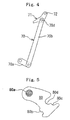
- the first operating lever 7 of the first releasing means is provided in a recess portion formed in an upper region of a back of the seat back 1 as shown in Fig. 1 , and coupled to a forward lobe of the first link plate 73 via a wire 7a of a first wire cable which is inserted through a tube 7b of the first wire cable.
- the wire 7a is drawn upward and the first link plate 73 is swung upward while pulling up the collapsible link member 70 through the braking link 71, whereby the actuating shafts 4 of the reclining lock mechanisms are synchronously rotated.
- the reclining lock mechanisms 3 are synchronously brought to unlocked states. In this condition, the person can cause the seat back 1 to be pivoted forward or rearward in one motion and cause the angle of the seat back 1 relative to the vehicle body floor to be adjusted.
- the pulling operation of the first operating lever 7 causes the entire components including the first link plate 73, the braking link 71 and the link bar member 70 to be pulled up, whereby the actuating shaft 4 of the first reclining lock mechanism 3 is rotated, an actuating shaft of the second reclining lock mechanism is synchronously rotated and the reclining lock means is then unlocked.
- the entire components including the first link plate 73, the braking link 71 and the link bar member 70 come down by gravity and the actuating shafts of the reclining lock mechanisms are synchronously rotated back, whereby the reclining lock mechanisms are locked.
- the seat back is locked with respect to the vehicle body floor.
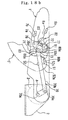
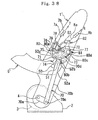
- the tipping-up lock means is provided on the one side of the vehicle seat. As shown in Fig. 2 , the rear portion of the side bracket 5' of the seat cushion has a substantially semicircular arc-shaped edge extending about the support pin 50 of the side bracket 5' of the seat cushion.
- the tipping-up lock means includes first and second cutout teeth 52a, 52c, provided at the substantially semicircular arc-shaped edge of the side bracket 5' so as to be spaced apart from each other, and a latch 80 and a cam member 81 which are supported to side bracket 1' of the seat back.1.
- the first cutout tooth 52a serves as means to facilitate causing of the seat cushion 5 to be locked in the first used position at which the seat cushion takes the substantially horizontal posture.
- the second cutout tooth 52c serves as means to facilitate causing of the seat cushion to be locked in a tipped-up position at which the seat cushion becomes opposed to the seat back located in a second used position at which the seat back takes a substantially vertical posture.
- the latch 80 is pivotally supported at a forward portion thereof to the side bracket 1' of the seat back by a support pin 80a so as to be swingable to an upward direction from a rearward direction.
- the latch 80 is provided at a lower edge region of a rearward portion thereof with a projecting tooth 80b which is adapted to be selectively and releasably engaged with the first and second cutout teeth 52a, 52c of the side bracket 5' ( Fig. 2 ).
- the projecting tooth 80b of the latch 80 is configured to include two spaced apart projecting tooth-portions.
- the first cutout tooth 52a is configured to include a recess portion which is adapted to receive the projecting tooth 80b of the latch 80 during returning of the seat cushion to the first used position from the tipped-up position and has a length sufficient to allow the seat back in the second used position to be angularly adjusted rearward in the condition where the seat cushion is locked in the first used position.
- a third cutout tooth (not shown) which serves as means to facilitate causing of the seat cushion to be locked in a middle position between the first used position and the tipped-up position of the seat cushion may be provided at the substantially semicircular arc-shaped edge of the side bracket 5' of the seat cushion so as to be arranged between the first and second cutout teeth 52a, 52c.
- the cam member 81 includes a cam body and a lower portion extending downward from the cam body.
- the cam member 81 is swingably supported at the cam body to the side bracket 1' of the seat back 1 by the support pin 77 of the first link plate 73, with the lower portion thereof being directed to an upper region of the rearward portion of the latch 80.
- the latch 80 is formed in the upper region of the rearward portion thereof with an engaging step portion 80c against which the lower portion of the cam member 81 is releasably abutted.
- the lower portion of the cam member 81 is abutted against the engaging step portion 80c of the latch 80, whereby the cam member 81 functions as a prop with respect to the latch 80, so that the engagement between the projecting tooth 80b of the latch 80 and each of the first and second cutout teeth 52a, 52c of the side bracket 5' of the seat cushion 5 can be positively maintained.
- an angle of the cam member 81 with respect to the latch 80 is set in such a manner that an angle ⁇ between a reference line L 1 connecting an axial center O 1 of the support pin 80a of the latch 80 and an abutment point P of the cam member 81 against the engaging step portion 80c of the latch 80, and a line L 2 connecting an axial center O 2 of the support pin 77 of the cam member 81 and the abutment point P is kept to be an acute angle.
- a bottom surface of the engaging step portion 80c of the latch 80 is formed so as to be adjacent the projecting tooth 80b of the latch 80, so that the reference line L 1 is set so as to descend rearward from the axial center O 1 of the support pin 80a of the latch 80.
- the lower portion of the cam member 81 is formed into a substantially semielliptical shape.
- the bottom surface of the engaging step portion 80c of the latch 80 is formed so as to have a substantially J-shape which allows the lower portion of the cam member 81 to be easily abutted against the engaging step portion 80c.
- the substantially J-shaped bottom surface of the engaging step portion 80c is formed so as to have a curve which allows at least half or more region of the lower portion of the cam member 81 to be received by the engaging step portion 80c, so that the lower portion of the cam member 81 can be positively abutted against the engaging step portion 80c of the latch 80 and stably received by the engaging step portion 80c.
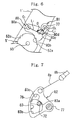
- the second releasing means for unlocking the tipping-up lock means includes a recess portion 80d ( Fig. 5 ) formed in the upper region of the rearward portion of the latch 80 for allowing of the cam member 81 to be swung up, a second link plate 82, and a second operating lever 8 ( Fig. 1 ).
- the recess portion 80d formed in the latch 80 extends continuously from an edge of the engaging step portion 80c and may be formed so as to have a depth which is not less than a height of an engaged region between the projecting tooth 80b of the latch 80 and each of the cutout teeth 52a, 52c and allows the projecting tooth 80b of the latch 80 to be escapingly disengaged from each of the cutout teeth 52a, 52c.
- the recess portion 80d of the latch 80 is formed so as to have a substantially U-shape (see Fig. 5 ) which has a depth larger than the height of the engaged region between the projecting tooth 80d and each of the cutout teeth 52a, 52c and fits the lower portion of the cam 81.
- the recess portion 80d of the latch 80 serves to allow the cam member 81 to be swung up in such a manner that the lower portion of the cam member 81 is disengaged from the engaging step portion 80c of the latch 80 and slips into the recess portion 80d.
- the latch 80 is swung upwardly in such a manner that the projecting tooth 80b is positively disengaged from any one of the cutout teeth 52a, 52c of the side bracket 5' of the seat cushion.
- the latch 80 is held so as to be stably swingable with resort to a holding plate 90 (see Fig. 3 ) which is supported by the support pin 50 of the side bracket 5' and the support pin 80a of the latch 80.
- the second link plate 82 is supported to the side bracket 1' of the seat back by the support pin 77 of the first link plate 73 so as to be swingable together with the cam member 81.
- As the second link plate 82 there is employed a link plate which is formed so as to have a substantially sector-shape which becomes gradually wider radially from a base portion thereof which is supported by the support pin 77.
- the first link plate 73, the cam member 81, and the second link plate 82 are mounted to the support pin 77 which is rotatably supported to the side bracket 1' of the seat back. More particularly, the cam member 81 and the second link plate 82 are fixed to the support pin 77, so that they are swingable together.
- the second link plate 82 is formed with an opening hole 83 which receives the induction pin 72 of the braking link 71.
- the opening hole 83 of the second link plate 82 has a middle hole edge region 83a against which the induction pin 72 of the braking link 71 is adapted to be engagingly abutted when the entire vehicle seat is located at a used position of the entire vehicle seat, a lower hole edge region 83b toward which the induction pin 72 of the braking link 71 is adapted to be escapingly moved from the middle hole edge region 83a when the seat cushion is tipped up, and an upper hole edge region 83c toward which the induction pin 72 of the braking link 71 is adapted to be escapingly moved when the seat cushion is in the tipped-up condition and the reclining lock means is unlocked.
- the term "used position of the entire vehicle seat” means a position at which the seat cushion takes the substantially horizontal posture and the seat back takes the substantially vertical posture.
- the second link plate 82 is coupled to the second operating lever 8 via a wire 8a of a second wire cable which is inserted through a tube 8b of the second wire cable.
- the second operating lever 8 is provided in a recess portion formed in a bottom region of a forward section of the seat cushion 5.
- the seat cushion can be brought to a condition where it is allowed to be tipped up in one motion by the person, as will be discussed in detail hereinafter.
- the pulling operation of the second operating lever 8 causes the second link plate 82 and the cam member 81 to be swung, whereby the latch 80 is pulled upward and consequently the tipping-up lock means is brought to an unlocked state. Moreover, when the second operating lever 8 is released from the pulled-state, the entire components which include the second link plate 82, the cam member 81 and the latch 80 come down by gravity, whereby the tipping-up lock means is brought to a locked-state.
- the stand leg portion 6 is typically urged toward a stored position under the seat cushion by a tension spring 10 which is a coil spring or a helical torsion spring and retained at one end thereof to an upper end region of one of the spaced apart vertical portions of the U-shaped stand leg portion 6 and retained at the other end thereof to the one of the side brackets of the seat cushion (not shown).
- a tension spring 10 which is a coil spring or a helical torsion spring and retained at one end thereof to an upper end region of one of the spaced apart vertical portions of the U-shaped stand leg portion 6 and retained at the other end thereof to the one of the side brackets of the seat cushion (not shown).
- a wire 11a of a third wire cable 11 which is inserted through a tube 11c of the third wire cable 11 is coupled at one end portion thereof to the upper end region of the vertical portion of the stand leg portion 6 and coupled at the other end portion thereof (not shown) to the seat back.
- the other end portion of the wire of the third wire cable 11 is supported to a retaining piece 12 which is provided at a suitable portion of the seat back frame.
- the other end portion of the wire of the third wire cable 11 is provided with a spherical end stop 11b and penetrated through a slit of the retaining piece 12 so as to be movable relative to the retaining piece 12.
- any suitable compensator (not shown) for compensating a pulling force exerted on the wire of the third wire cable 11 and adjusting a total length of the wire of the third wire cable 11 is provided at a suitable portion of the wire of the third wire cable 11.
- the wire of the third wire cable 11 When the seat cushion is located at the first used position, the wire of the third wire cable 11 is in a condition shown in Fig. 9a .
- the wire of the third wire cable 11 is pushed so as to overcome an action of the tension spring 10 (as shown in Fig. 9b ) and allow the stand leg portion 6 to be pivoted toward a developed position thereof until the seat cushion reaches a position just before the tipped-up position.
- the stand leg portion 6 can be pivoted toward the stored position synchronously with the tipping-up movement of the seat cushion and diving-down movement of the entire vehicle seat, and can be pivoted toward the developed position synchronously with returning of the entire seat toward the used position of the entire vehicle seat or returning of the seat cushion toward the first used position.
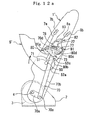
- the tip-up/dive down type reclining vehicle seat of the first embodiment which is constructed as discussed above, in a condition where the entire vehicle seat is located at the used position thereof (see Fig. 1 ) and the reclining lock means and the tipping-up lock means are in the locked states (see Fig. 2 ), the lower end portion of the braking link 71 is stoppingly engaged with the stopper pin 51 provided on the side bracket 5' of the seat cushion 5 and the induction pin 72 of the braking link 71 is located at a rearward end of the guide hole 78 formed in the first link plate 73, whereby the used position of the entire vehicle seat is determined.
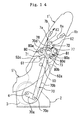
- the latch 80 is swung up, whereby the projecting tooth 80b of the latch 80 is disengaged from the first cutout tooth 52a of the side bracket 5' of the seat cushion as shown in Fig. 11 .
- the recess portion 80d of the latch 80 is configured to have the depth larger than the height of the engaged region between the projecting tooth 80b of the latch 80 and the cutout tooth 52a of the side bracket 5' of the seat cushion 5 as discussed above, so that as the lower portion of the cam 81 slips into the recess portion 80d, the latch 80 is considerably swung up, whereby the projecting tooth 80b can be positively disengaged from the first cutout tooth 52a of the side bracket 5' of the seat cushion.
- the tipping-up lock means is brought to the unlocked state, that is, the seat cushion is brought to a condition where it is allowed to be tipped up.
- the tipping-up lock means is unlocked, namely, the projecting tooth 80b of the latch 80 is disengaged from the cutout tooth 52a of the side bracket 5'
- the cutout tooth 52a of the side bracket 5' of the seat cushion is moved away from the first cutout tooth 80b of the latch 80 as shown in Fig. 12a .
- the seat cushion 5 is tipped up from the first used position to the tipped-up position around the support pins 50 as shown in Figs. 12b and 12c .
- the second link plate 82 When the second operating lever 8 is pull-operated at the time of causing the tipping-up lock means to be unlocked, the second link plate 82 is swung upward and the induction pin 72 of the braking link 71 is escapingly moved toward the lower hole edge region 83b from the middle hole edge region 83a of the second link plate 82 ( Fig. 7 ) relative to the second link plate 82 as shown in Fig. 12a , so that the induction pin 72 of the braking link 71 is not drawn up by the second link 82 and the reclining lock mechanisms are not unlocked.
- the person can cause the seat back 1 to be pivoted rearward so as to be angularly adjusted as shown in Fig. 16 .
- the components which include the first link plate 73, the braking link 71, the link bar member 70, the second link plate 82, the cam member 81 and the latch 80 come down by gravity and are returned to their original positions, whereby the reclining lock means and the tipping-up lock means are locked and the entire seat is maintained in a used position thereof at which the seat back is angularly adjusted rearward.
- the seat back is pivoted forward and the entire vehicle seat can be dived down and stored in a space on the lower step portion f 2 of the vehicle body floor F as shown in Figs. 17a and 17b .
- the components which include the first link plate 73, the braking plate 71, the link bar member 70, the second link plate 82, the cam member 81 and the latch 80 cannot come down by gravity as shown in Figs. 18a and 18b during the forward pivotal movement of the seat back from the substantially vertical position, so that the reclining lock means and the tipping-up lock means are maintained in the unlocked states.
- the person causes the entire seat to be forward pivoted to a certain extent while holding the seat back with his/her hand. Then, the person removes his/her hand from the recess portion of the seat back to the recess portion of the seat cushion and causes the seat cushion to be lifted down while holding the seat cushion with his/her hand.
- the entire vehicle seat can be dived down and stored in the space on the lower step portion f 2 of the vehicle body floor F.
- the reclining lock means and the tipping-up lock means are still maintained in the unlocked states, so that when the vehicle seat in the dived-down state is to be returned to the used position of the entire vehicle seat, the person inserts his/her hand into the recess portion of the seat back, and can easily lift the entire vehicle seat up from the dived-down position shown in Fig. 19a to a position shown in Fig. 19b and then return the vehicle seat to the used position of the entire vehicle seat ( Fig. 1 ), while holding the seat back with his/her hand.
- the stopper pin 51 projecting from the side bracket 5' of the seat cushion 5 is separated from the lower portion of the braking link 71 and the braking link 71 comes down by gravity as shown in Fig. 20 , so that the induction pin 72 of the braking link 71 is located at a forward end of the guide hole 78 formed in the first link plate 73.
- the seat cushion 5 In the condition where the tipping-up lock means is maintained in the locked state, the seat cushion 5 is prevented from being pivoted with respect to the seat back 1 as shown in Figs. 22a and 22b , so that the seat cushion 5 can be forward pivoted together with the seat back 1 and the entire vehicle seat can be dived down as shown in Fig. 23 and then stored in the space on the lower step portion of the vehicle body floor.
- the diving-down movement of the entire vehicle seat can be performed by the person in the same manner as discussed above. That is, the person inserts his/her hand into the recess portion of the seat back, causes the entire seat to be forward pivoted to the certain extent while holding the seat back with his/her hand. Then, the person removes his/her hand from the recess portion of the seat back to the recess portion of the seat cushion, and causes the seat cushion to be lifted down while holding the seat cushion with his/her hand.
- the entire vehicle seat can be dived down and stored in the space on the lower step portion f 2 of the vehicle body floor F.
- the tipping-up lock means is kept in the locked state, so that the entire vehicle seat can be angularly adjusted rearward as shown in Fig. 24 .
- the stand leg portion 6 can be pivoted toward the stored position synchronously with such movement of the seat cushion or the entire vehicle seat.
- the stand leg portion 6 can be pivoted toward the developed position synchronously with such movement of the entire vehicle seat or the seat cushion.
- second tipping-up lock means, third releasing means and fourth releasing means which are constructed in the same manner as the first tipping-up lock means, the first releasing means and the second releasing means are done, respectively, except that the third and fourth releasing means do not include any operating levers, may be provided on the other of the both sides of the vehicle seat.
- a fourth wire cable is connected between the first operating lever 7 and a link plate of the third releasing means and a fifth wire cable is connected between the second operating lever 8 and a link plate of the fourth releasing means, so that when the first operating lever is pull-operated, the first releasing means and the third releasing means can be synchronously actuated and, when the second operating lever is pull-operated, the second releasing means and the fourth releasing means can be synchronously actuated.
- a tip-up/dive down type vehicle seat according to a second embodiment of the present invention will be discussed hereinafter.
- the second embodiment is constructed in a substantially same manner as the first embodiment is done, except for following points.
- components that are substantially similar to those of the vehicle seat shown in Figs. 1 to 24 are designated by the same reference numerals.
- the vehicle seat according to the second embodiment includes the seat back 1 (see Fig.
- the reclining lock means including the first and second reclining lock mechanisms 3 for releasably locking the seat back 1 and preventing the pivotal movement of the seat back 1 (only first reclining mechanism 3 is shown in Fig. 33 ), the first releasing means for unlocking the first and second reclining lock mechanisms 3 and allowing the seat back to be brought to the condition where the seat back is allowed to be pivoted forward and rearward (see Fig.
- the tipping-up lock means for releasably locking the seat cushion 5 and preventing the tipping-up movement of the seat cushion (see Fig. 33 ), and the second releasing means for unlocking the tipping-up means and allowing the seat cushion to be brought to the condition where the seat cushion is allowed to be tipped up (see Fig. 33 ).
- the reclining lock mechanisms 3 are provided between the lower end portions of the spaced apart side brackets of the seat back 1 and the spaced apart base brackets 2 mounted on the upper step portion f 1 of the vehicle body floor F so as to stand up from the upper step portion f1, so that the seat back 1 is allowed to be releasably locked with respect to the upper step portion f1 of the vehicle body floor F by the reclining lock mechanisms 3.
- the seat cushion 5 of the second embodiment includes the spaced apart side brackets serving as the side frame sections of the seat cushion frame for the seat cushion 5.
- the spaced apart side brackets of the seat cushion 5 are coupled at the rear end portions thereof to the portions of the side brackets of the seat back 1, which are adjacent the lower end portions of the spaced apart side brackets of the seat back 1, by the support pins 50, whereby the seat cushion 5 is pivotally supported to the seat back 1 so as to be allowed to be tipped up.
- the vehicle seat of the second embodiment further includes the substantially U-shaped stand leg portion 6 in outline which is pivotally connected at the upper end regions of the spaced apart vertical portions thereof to the side brackets of the seat cushion 5 by the support pins 6a.
- the receiving base 6b for receiving and engaging the lower horizontal portion of the stand leg portion 6 is mounted on the lower step portion f 2 of the vehicle body floor F.
- the stand leg portion 6 is adapted to be engaged at the lower horizontal portion thereof with the receiving base 6b so as to obliquely stand up from the lower step portion f 2 of the vehicle body floor F, whereby when the seat cushion is located at the first used position, the seat cushion is horizontally supported by the stand leg portion 6 which is releasably engaged with the receiving base 6b.
- the reclining lock means of the second embodiment is adapted to be unlocked by pull-operating the first operating lever 7 which is provided in the recess portion of the back of the seat back 1.
- the person can cause the seat back 1 to be pivoted forward or rearward in one motion while holding the seat back with his/her hand.
- the tipping-up lock means of the second embodiment is adapted to be unlocked by pull-operating the second operating lever 8 which is provided in the recess portion formed in the bottom region of the forward section of the seat cushion 5.
- the tipping-up lock means is unlocked, the person can cause the seat cushion 5 to be tipped up in one motion while holding the seat cushion with his/her hand.
- the side bracket 5' of the seat cushion 5 of the second embodiment is provided at the rear portion thereof with the substantially semicircular-arc shaped edge which extends about the support pin 50 of the side bracket 5' of the seat cushion.
- the stopper pin 51 is provided on the side bracket 5' so as to be arranged upward of the support pin 50 of the side bracket 5' of the seat cushion 5.
- the vehicle seat according to the second embodiment of the present invention is different from the vehicle seat of the first embodiment in that in addition to the first and second cutout teeth 52a, 52c, the tipping-up lock means includes a third cutout tooth 52b provided at the substantially semicircular-arc shaped edge of the side bracket 5' so as to be arranged between the first and second cutout teeth 52a, 52c and serving as means to facilitate causing of the seat cushion to be locked in a middle position between the first used position and the tipped-up position of the seat cushion.
- the first cutout tooth 52a of the second embodiment is configured to include the recess portion which is adapted to receive the projecting tooth 80b of the latch 80 during the returning of the seat cushion to the first used position from the tipped-up position and has a length X sufficient to allow the seat back in the second used position to be angularly adjusted rearward in the condition where the seat cushion is located in the first used position.
- the first releasing means of the second embodiment is different from the first releasing means of the first embodiment in that, in addition to the collapsible link bar member 70, the first braking link 71 coupled to the collapsible link bar member 70 and having the induction pin 72, the first link plate 73, and the first operating lever 7, the first releasing means of the second embodiment includes a second braking link 74 provided at the first link plate 73 and an elongated bar 75 collapsibly supported to an upper end portion of the second braking link 74 and having a wire retaining pin 76 projecting laterally from the elongated bar 75 at a free end thereof.
- the collapsible link bar member 70 of the second embodiment includes the lower bar portion 70a coupled at the first end thereof to the actuating shaft 4 of the first reclining lock mechanism 3 and the upper bar portion 70b connected at the first end thereof to the second end of the lower bar portion 70a by the support pin 70c and extending upward.
- the first braking link 71 of the second embodiment is swingably connected at the substantially middle portion thereof to the second end of the upper bar portion 70b by the support pin 70d.
- the first link plate 73 of the second embodiment is formed into a substantially triangular shape having three lobes as shown in Fig. 28 , and swingably supported at a rearward lobe thereof to the side bracket 1' of the seat back 1 by the support pin 77 as shown in Figs. 26 and 27 .
- the first link plate 73 of the second embodiment has the circular arc-shaped guide hole 78 formed therein so as to extend about the support pin 70d of the first braking link 71.
- the induction pin 72 of the first braking link 71 is inserted through the guide hole 78 of the first link plate 73.
- the first link plate 73 of the second embodiment is different from the first link plate 73 of the first embodiment in that it has a substantially L-shaped control hole 79 formed therein.
- the control hole 79 includes a horizontal engaging hole portion 79a located at a position lower than the forward end of the guide hole 78, and a vertical hole portion 79b vertically extending so as to continue from the horizontal engaging hole portion 79a.
- the wire retaining pin 76 of the elongated bar 75 is inserted through the control hole 79 of the first link plate 73.
- the second braking link 74 is mounted at a middle portion thereof to the first link plate 73 by a support pin 74a in such a manner that a lower portion of the second braking link 74 is adapted to be abutted against the stopper pin 51 from the direction opposite to the direction from which the lower portion of the first braking link 71 is abutted against the stopper pin 51.
- the elongated bar 75 is connected to the upper end portion of the second braking link 74 by a support pin 74b.
- the vehicle seat of the second embodiment is further different from the vehicle seat of the first embodiment in that the wire 7a of the first wire cable of the first operating lever 7 is connected to the wire retaining pin 76 projecting laterally from the upper end of the elongated bar 75.
- the components including the first link plate 73, the first braking link 71 and the link bar member 70 come down by gravity, whereby the actuating shafts 4 of the reclining mechanisms are rotated back and the reclining lock means is brought to the locked state.
- the tipping-up lock means of the second embodiment includes the first, second and third cutout teeth 52a, 52c, 52b provided at the substantially semicircular arc-shaped edge of the side bracket 5', the latch 80 swingably supported at the forward portion thereof to the side bracket 1' of the seat back by the support pin 80a, and the cam member 81 supported to the support pin 77 of the first link plate 73.
- the latch 80 of the second embodiment is provided at the lower edge region of the rearward portion thereof with the projecting tooth 80b as shown in Fig. 29 .
- the projecting tooth 80b is adapted to be selectively and releasably engaged with the first, second and third cutout teeth 52a, 52c, 52b of the side bracket 5' of the seat cushion 5.
- the projecting tooth 80b is configured to include the two spaced apart projecting tooth-portions.
- the cam member 81 is swingably supported at the cam body thereof to the side bracket 1' of the seat back 1 by the support pin 77 of the first link plate 73 with the lower portion thereof being directed to the upper region of the rearward portion of the latch 80.
- the latch 80 of the second embodiment has the engaging step portion 80c formed in the upper region of the rearward portion thereof.
- the lower portion of the cam member 81 is releasably abutted against the engaging step portion 80c of the latch 80, whereby the cam member 81 functions as the prop with respect to the latch 80, so that the engagement between the projecting tooth 80b of the latch 80 and each of the cutout teeth 52a, 52b, 52c of the side bracket 5' of the seat cushion 5 can be positively maintained.
- the angle of the cam member 81 relative to the latch 80 is set in such a manner that the angle ⁇ between the reference line L 1 connecting the axial center O 1 of the support pin 80a of the latch 80 and the abutment point P of the cam member 81 against the engaging step portion 80c of the latch 80, and the line L 2 connecting the axial center O 2 of the support pin 77 of the cam member 81 and the abutment point P is kept to be an acute angle, as shown in Fig. 29 .
- the lower portion of the cam member 81 of the second embodiment is formed into the substantially semielliptical shape.
- the bottom surface of the engaging step portion 80c of the latch 80 is formed so as to have the substantially J-shape which allows the lower portion of the cam member 81 to be easily abutted against the engaging step portion 80c.
- the substantially J-shaped bottom surface of the engaging step portion 80c is formed so as to have a curve which allows at least half or more region of the lower longitudinal portion of the cam member 81 to be received by the engaging step portion 80c, so that the lower longitudinal portion of the cam member 81 can be positively abutted against the engaging step portion 80c of the latch 80 and stably received by the engaging step portion 80c.
- the second releasing means of the second embodiment includes the recess portion 80d formed in the upper region of the rearward portion of the latch 80 for allowing the swinging movement of the cam member 81, the second link plate 82 supported to the side bracket 1' of the seat back 1 by the support pin 77 of the first link plate 73, and the second operating lever 8.
- the second operating lever 8 is coupled to the second link plate 82 via the wire 8a of the second wire cable that is inserted through the tube 8b of the second wire cable.
- the recess portion 80d of the latch 80 extends continuously from the edge of the engaging step portion 80c and is formed so as to have the depth which is not less than the height of the engaged region between the projecting tooth 80b of the latch 80 and each of the cutout teeth 52a, 52b, 52c and allows the projecting tooth 80b of the latch 80 to be escapingly disengaged from each of the cutout teeth 52a, 52b, 52c.
- the recess portion 80d of the latch 80 is formed so as to have the substantially U-shape which has the depth larger than the height of the engaged region between the projecting tooth 80d and each of the cutout teeth 52a, 52b, 52c and fits the lower portion of the cam member 81.
- the recess portion 80d of the latch 80 serves to allow the cam member 81 to be swung up in such a manner that the lower portion of the cam member 81 is disengaged from the engaging step portion 80c of the latch 80 and slips into the recess portion 80d.
- the latch 80 is swung up in such a manner that the projecting tooth 80b is positively disengaged from any one of the cutout teeth 52a, 52b, 52c of the side bracket 5' of the seat cushion.
- the latch 80 of the second embodiment is held so as to be stably swingable with respect to the holding plate 90 ( Fig. 27 ) which is supported by the support pin 50 of the side bracket 5' and the support pin 80a of the latch 80.
- first link plate 73, the second link plate 82 and the cam member 81 are supported to the support pin 77 which is rotatably supported to the side bracket 1' of the seat back 1.
- the cam member 81 and the second link plate 82 are fixed to the support pin 77, so that they are swingable together.
- the second link plate 82 of the second embodiment is formed with the opening hole 83 which receives the induction pin 72 of the first braking link 71 and has the middle hole edge region 83a against which the induction pin 72 of the first braking link 71 is adapted to be engagingly abutted when the entire vehicle seat is located at the used position of the entire vehicle seat, the lower hole edge region 83b toward which the induction pin 72 of the first braking link 71 is adapted to be escapingly moved from the middle hole edge region 83a when the seat cushion is tipped up, and the upper hole edge region 83c toward which the induction pin 72 is adapted to be escapingly moved when the seat cushion is in the tipped-up condition and the reclining lock means is unlocked.
- the second link plate 82 and the cam member 81 are swung upward together and the latch 80 is swung upward by the upward movement of the cam member 81, whereby the tipping-up lock means is unlocked.
- the entire components which include the second link plate 82, the cam member 81 and the latch 80 come down by gravity, whereby the tipping-up lock means is brought to the locked state.
- the stand leg portion 6 of the second embodiment is typically urged toward the stored position under the seat cushion by the tension spring 10 which is retained at the one end thereof to the upper end region of the one of the spaced apart vertical portions of the U-shaped stand leg portion 6 and retained at the other end thereof to the one of the side brackets of the seat cushion.
- the wire 11a of the third wire cable 11 which is inserted through the tube 11 c of the third wire cable 11 is coupled at the one end portion thereof to the upper end region of the vertical portion of the stand leg portion 6 and coupled at the other end portion thereof to the seat back.
- the other end portion of the wire of the third wire cable 11 of the second embodiment is supported to the retaining piece 12 which is provided at the suitable portion of the seat back frame.
- the other end portion of the wire of the third wire cable 11 is provided with the spherical end stop 11b and penetrated through the slit of the retaining piece 12 so as to be movable relative to the retaining piece 12.
- any suitable compensator for compensating the pulling force exerted on the wire of the third wire cable 11 and adjusting the total length of the wire of the third wire cable 11 is provided at the suitable portion of the wire of the third wire cable 11.
- the wire of the third wire cable 11 is in the condition shown in Fig. 9a .
- the wire of the third wire cable 11 is pushed so as to overcome the action of the tension spring 10 (as shown in Fig. 9b ) and allow the stand leg portion 6 to be pivoted toward the developed position thereof until the seat cushion reaches a position just before the tipped-up position.
- the stand leg portion 6 can be pivoted toward the stored position synchronously with the tipping-up movement of the seat cushion and the diving-down movement of the entire vehicle seat, and can be pivoted toward the developed position synchronously with returning of the entire seat toward the used position of the entire vehicle seat or returning of the seat cushion to the first used position.
- the tip-up/dive down type reclining vehicle-seat of the second embodiment which is constructed as discussed above, in a condition where the entire seat is located at the used position thereof ( Fig. 1 ) and the reclining lock means and the tipping-up lock means are in the locked states ( Fig. 26 ), the lower end portion of the first braking link 71 is stoppingly engaged with the stopper pin 51 provided on the side bracket 5' of the seat cushion 5, so that the induction pin 72 of the first braking link 71 is located at the rear end portion of the guide hole 78 of the first link plate 73, whereby the used position of the entire vehicle seat is determined.
- the second braking link 74 is hanged down from the first link plate 73 by gravity and assumes a posture in which a lower portion of the second braking link 74 is located close to the stopper pin 51 but is not contacted with the stopper pin 51. Therefore, the elongated bar 75 is in a condition where it becomes collapsed relative to the second braking link 74, and the wire retaining pin 76 is located in the engaging hole portion 79a of the control hole 79 formed in the first link plate 73.
- the induction pin 72 of the first braking link 71 is located at the rearward end of the guide hole 78 of the first link plate 73 and engaged with the middle hole edge 83a of the opening hole 83 formed in the second link plate 82, so that the second link plate 82 is also pulled up by the drawing-up of the wire retaining pin 76.
- the second link plate 82 is also swung upward as discussed above, whereby the cam member 81 is swung upward in such a manner that the lower portion of the cam member 81 is disengaged from the engaging step portion 80c of the latch 80 and slips into the recess portion 80d of the latch 80.
- the latch 80 is swung up in such a manner that the projecting tooth 80b is disengaged from the first cutout tooth 52a of the side bracket 5', whereby the tipping-up lock means is also unlocked.
- the recess portion 80d of the latch 80 is configured to have the depth larger than the height of the engaged region between the projecting tooth 80b of the latch 80 and the cutout tooth 52a of the side bracket 5' as discussed above, so that as the lower portion of the cam member 81 slips into the recess portion 80d, the latch is considerably swung up, whereby the projecting tooth 80b can be positively disengaged from the first cutout tooth 52a of the side bracket 5'.
- the seat back can be angularly adjusted rearward by an extent corresponding to the length X of the recess portion of the first cutout tooth 52a ( Fig. 25 ), as shown in Fig. 33 .
- the components which include the first link plate 73, the first braking link 71, the link bar member 70, the second link plate 82, the cam member 81, and the latch 80 come down by gravity, whereby the reclining lock means and the tipping-up lock means are locked.
- the entire vehicle seat is maintained in the used position thereof.
- the seat back 1 In the condition where the reclining lock means and the tipping-up lock means are unlocked, the seat back 1 is pivoted forward and the entire vehicle seat can be dived down and stored in the space on the lower step portion f 2 of the vehicle body floor F, as shown in Figs. 34a and 34b .
- the components which include the first link plate 73, the first braking plate 71, the link bar member 70, the second link plate 82, the cam member 81 and the latch 80 cannot come down by gravity as shown in Figs. 35a and 35b during the forward pivotal movement of the seat back from the substantially vertical position, so that the reclining lock means and the tipping-up lock means are maintained in the unlocked states.
- the person causes the entire seat to be forward pivoted to a certain extent while holding the seat back with his/her hand. Then, the person removes his/her hand from the recess portion of the seat back to the recess portion of the seat cushion and causes the seat cushion to be lifted down while holding the seat cushion with his/her hand.
- the entire vehicle seat can be dived down and stored in the space on the lower step portion f 2 of the vehicle body floor F.
- the reclining lock means and the tipping-up lock means are still maintained in the unlocked states, so that when the vehicle seat in the dived-down sate is to be returned to the used position of the entire vehicle seat, the person inserts his/her hand into the recess portion of the seat back, and can easily lift the entire vehicle seat up from the dived-down position shown in Fig. 36a to a position shown in Fig. 36b and then return the vehicle seat to the used position of the entire vehicle seat ( Fig. 1 ), while holding the seat back with his/her hand.
- the second link plate 82 is swung up about the support pin 77 and the cam member 81 is also swung up together with the second link plate 81 in such a manner that the lower portion of the cam member 81 is disengaged from the engaging step portion of the latch 80 and slips into the recess portion 80d of the latch 80, whereby the latch 80 is swung up in such a manner that the projecting tooth 80b of the latch 80 is disengaged from the cutout tooth 52a of the side bracket 5'.
- the tipping-up lock means is brought to the unlocked-state ( Fig. 32 ).
- the induction pin 72 When the tipping-up lock means is unlocked, the induction pin 72 is escapingly moved toward the lower hole edge region 83b of the opening hole 83 relative to the second link plate 82. Therefore, the induction pin 72 is not drawn up by the second link plate 82, so that the reclining lock means is not unlocked.
- the cutout tooth 52a of the side bracket 5' of the seat cushion is moved away from the first projecting tooth 80b of the latch 80.
- the seat cushion 5 is tipped up from the first used position to a middle position between the first used position and the tipped-up position (see Fig. 38 ) or tipped up from the first used position to the tipped-up position (see Fig. 39 ).
- the tipping-up lock means is unlocked. In this condition, the seat cushion can be returned to the first used position.
- the first link plate 73 When the first operating lever 7 is pull-operated in order that the seat cushion is pivoted forward together with the seat back from the tipped-up position, dived down and stored in the space on the lower step portion of the vehicle body floor, the first link plate 73 is swung up as shown in Fig. 41 and the induction pin 72 of the first braking link 71 which is located at the forward end of the guide hole 78 of the first link plate 73 is drawn up, whereby the reclining lock means is unlocked as discussed above.
- the induction pin 72 of the first braking link 71 is located at the forward end of the guide hole 78 of the first link plate 73 and escapingly moved toward the upper hole edge region 83c of the opening hole 83 formed in the second link plate 82, so that the second link plate 82 is not swung and the tipping-up lock means is maintained in the locked-state.
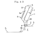
- the tipping-up lock means is maintained in the locked-state, so that the seat cushion can be pivoted forward together with the seat back without pivoting with respect to the seat back as shown in Fig. 42a , and the entire vehicle seat can be dived down in the condition where the tipping-up lock means is maintained in the locked-state as shown in Fig. 42b .
- the person When the entire seat is to be dived down and stored in the space on the lower step portion of the vehicle body floor, the person causes the vehicle seat to be pivoted forward by the certain extent, while holding the seat back with his/her hand, removes his/her hand from the seat back to the seat cushion and can cause the vehicle seat to be dived down while lifting the seat cushion down with his/her hand.
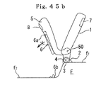
- the second braking link 74 When the seat cushion 5 is locked in the middle position, the second braking link 74 is kicked up by the stopper pin 51 as shown in Fig. 44 . At this time, the elongated bar 75 is pushed by the second braking link 74, whereby the wire retaining pin 76 is moved to a connecting hole portion between the horizontal engaging hole portion 79a and the vertical hole portion 79b of the control hole 79.
- the stand leg portion 6 can be pivoted toward the stored position synchronously with such movement of the seat cushion or the entire vehicle seat. Moreover, during the returning movement of the entire vehicle seat to the used position thereof or the returning movement of the seat cushion in the tipped-up sate to the first used position, the stand leg portion 6 can be pivoted toward the developed position synchronously with such movement of the entire vehicle seat or the seat cushion.
- second tipping-up lock means, third releasing means and fourth releasing means which are constructed in the same manner as the first tipping-up lock means, the first releasing means and the second releasing means are done, respectively, except that the third and fourth releasing means do not include any operating levers, may be provided on the other of the both sides of the vehicle seat.
- a fourth wire cable is connected between the first operating lever 7 and a link plate of the third releasing means and a fifth wire cable is connected between the second operating lever 8 and a link plate of the fourth releasing means, so that when the first operating lever is pull-operated, the first releasing means and the third releasing means can be synchronously actuated and, when the second operating lever is pull-operated, the second releasing means and the fourth releasing means can be synchronously actuated.
Landscapes
- Engineering & Computer Science (AREA)
- Aviation & Aerospace Engineering (AREA)
- Transportation (AREA)
- Mechanical Engineering (AREA)
- Seats For Vehicles (AREA)
Claims (5)
- Hoch- und herunterklappbarer Liegesitz für ein Fahrzeug, wobei
das Fahrzeug
einen Fahrzeugkarosserieboden (F) mit einem oberen Absatz- bzw. Stufenabschnitt (f1) und einem unteren Stufenabschnitt (f2) umfasst;
der hoch- und herunterklappbare Liegesitz umfasst:eine Sitzlehne (1), die ein Paar erster beabstandeter Seitenträger bzw. Halterungen umfasst;ein Sitzpolster (5), das ein Paar zweiter beabstandeter Seitenhalterungen umfasst;ein Paar dritter beabstandeter Basishalterungen (2), die geeignet sind, auf den oberen Stufenabschnitt (f1) montiert zu werden;Liegearretiermittel zum lösbaren Arretieren der Sitzlehne (1) ;wobei die Liegearretiermittel ein Paar von Liegearretiermechanismen (3) umfassen, von denen jeder zwischen einem unteren Endabschnitt einer entsprechenden der ersten beabstandeten Seitenhalterungen und einer entsprechenden der dritten beabstandeten Basishalterungen (2) bereitgestellt ist, so dass, wenn die Liegearretiermechanismen (3) arretiert sind, die Sitzlehne (1) in einer im Wesentlichen vertikalen Stellung arretiert werden kann, und wenn die Liegearretiermechanismen (3) unarretiert sind, zugelassen wird, dass die Sitzlehne (1) vorwärts und rückwärts geschwenkt und die Neigung eingestellt wird;wobei die Liegearretiermechanismen (3) Betätigungsschäfte (4) umfassen, die durch einen Verbindungsschaft miteinander gekoppelt sind;wobei die Liegearretiermechanismen (3) geeignet sind,entsperrt zu werden, wenn die Betätigungsschäfte (4) gedreht werden, und geeignet sind, arretiert zu wenden,wenn die Betätigungsschäfte (4) zurück gedreht werden;wobei das Sitzpolster (5) durch erste Haltestifte (50) schwenkbar zu Abschnitten der ersten beabstandeten Seitenhalterungen, die benachbart zu unteren Endabschnitten der ersten beabstandeten Seitenhalterungen sind, an hinteren Abschnitten seiner zweiten beabstandeten Seitenhalterungen gehalten wird, so dass das Sitzpolster (5) geeignet ist, hochgeklappt zu werden;einen Standbeinabschnitt (6), der schwenkbar zu vorderen Abschnitten der zweiten beabstandeten Seitenhalterungen gehalten wird und geeignet ist, lösbar in Bezug auf den unteren Stufenabschnitt (f2) des Fahrzeugkarosseriebodens (F) in Eingriff gebracht zu werden, um auf dem unteren Stufenabschnitt (f2) zu stehen;Hochklapparretiermittel auf wenigstens einer (1') der ersten beabstandeten Seitenhalterungen und wenigstens einer (5') der zweiten beabstandeten Seitenhalterungen zum lösbaren Arretieren des Sitzpolsters (5) in einer hochgeklappten Position, in der das Sitzpolster (5) in einer im Wesentlichen vertikalen Stellung entgegengesetzt zu der Sitzlehne (1) wird, und in einer Verwendungsposition, in der das Sitzpolster (5) eine im Wesentlichen horizontale Stellung einnimmt;ein erstes Lösemittel auf der wenigstens einen (1') der ersten beabstandeten Seitenhalterungen und der wenigstens einen (5') der zweiten beabstandeten Seitenhalterungen zum Entsperren der Liegearretiermittel; undein zweites Lösemittel auf der wenigstens einen (1') der ersten beabstandeten Seitenhalterungen und der wenigstens einen (5') der zweiten beabstandeten Seitenhalterungen zum Entsperren der Hochklapparretiermittel;wobei ein ganzer Fahrzeugsitz in einem Zustand, in dem das Sitzpolster (5) sich in der hochgeklappten Position befindet, oder in einem Zustand, in dem die Rückenlehne (1) in Bezug auf das Sitzpolster (5) in der Verwendungsposition nach vorne geklappt ist,heruntergeklappt und in einem Raum auf dem unteren Stufenabschnitt (f2) des Fahrzeugkarosseriebodens (F) gelagert werden kann,dadurch gekennzeichnet, dass ein Anschlagstift (51) an der wenigstens einen der zweiten beabstandeten Seitenhalterungen bereitgesellt ist, um aufwärts von dem entsprechenden der ersten Haltestifte (50) angeordnet zu sein;wobei das ersten Lösemittel umfasst: ein zusammenklappbares Verbindungsstangenelement (70), das an seinem unteren Endabschnitt mit entsprechenden der Betätigungsschäfte (4) der Liegearretiermechanismen (3) gekoppelt ist, eine Bremsverbindung (71) mit einem seitlich vorstehenden Einführungsstift (72), der an seinem oberen Ende bereitgestellt ist und durch einen zweiten Haltestift (70d) schwingbar mit seinem im Wesentlichen mittleren Abschnitt mit einem oberen Endabschnitt d e s zusammenklappbaren Verbindungsstangenelement (70) verbunden ist, wobei die Bremsverbindung (71) geeignet ist, aus einer Abwärtsrichtung stoppend mit dem Anschlagstift (51) in Eingriff gebracht zu werden, eine erste Verbindungsplatte (73), die durch einen dritten Haltestift (77) schwingbar zu der wenigstens einen (1') der beabstandeten Seitenhalterungen an ihrem hinteren Abschnitt gehalten wird und ein kreisförmiges bogenförmiges Führungsloch (78) hat, das sich um den zweiten Haltestift (70d) der Bremsverbindung (71) erstreckt, wobei der Zuführungsstift (72) der Bremsverbindung (71) durch das Führungsloch (78) der ersten Verbindungsplatte (73) eingesetzt ist, undeinen ersten Bedienhebel (7), der über einen Draht (7a) des ersten Drahtseils mit der ersten Verbindungsplatte (73) gekoppelt ist, so dass, wenn der erste Bedienhabel (7) zugbedient wird, die erste Verbindungsplatte (73), die Bremsverbindung (71) und das zusammenklappbare Verbindungsstangenelement hochgezogen werden, wodurch die Liegearretiermechanismen (3) entsperrt werden, und wenn der erste Bedienhebel (7) aus dem gezogenen Zustand gelöst wird, die erste Verbindungsplatte (73), die Bremsverbindung (71) und das zusammenklappbare Verbindungsstangenelement (70) durch die Schwerkraft herunterkommen, wodurch die Liegearretiermechanismen (3) arretiert werden;wobei wenigstens eine (5') der zweiten beabstandeten Seitenhalterungen einen hinteren Abschnitt mit einem im Wesentlichen halbkreisförmigen bogenförmigen Rand, der sich um einen ersten Haltestift (50) der wenigstens einen (5') der zweiten beabstandeten Seitenhalterungen erstreckt, umfasst;wobei die Hochklapparretiermittel umfassen: erste undzweite beabstandete ausgeschnittene Zähne (52a, 52c), die an dem im Wesentlichen halbkreisförmigen bogenförmigen Rand bereitgestellt sind, wobei der erste ausgeschnittene Zahn (52a) als Mittel dient, um zu erleichtern, dass bewirkt wird, dass das Sitzpolster (5) in der Verwendungsposition arretiert wird, und der zweite ausgeschnittene Zahn (52c) als Mittel dient, um zu erleichtern, dass bewirkt wird, dass das Sitzpolster (5) in der hochgeklappten Position arretiert wird, einen Riegel (80), der durch einen vierten Haltestift (80a) schwenkbar an seinem vorderen Ende an der wenigstens einen (1') der ersten beabstandeten Seitenhalterungen gehalten wird, wobei der Riegel (80) einen vorstehenden Zahn (80b) hat, der in einem unteren Randbereich seines hinteren Abschnitts bereitgestellt ist, wobei der vorstehende Zahn (80b) geeignet ist, selektiv und lösbar mit den ersten und zweiten ausgeschnittenen Zähnen (52a, 52c) in Eingriff gebracht zu werden, und einen Eingreifstufenabschnitt (80c), der in einem oberen Bereich des hinteren Abschnitts des Riegels (80) bereitgestellt ist, und ein Nockenelement (81) mit einem Nockenkörper und einem unteren Abschnitt, der sich von dem Nockenkörper nach unten erstreckt, wobei das Nockenelement (81) durch den dritten Haltestift (77) der ersten Verbindungsplatte (73) schwingbar zu der wenigstens einen (1') der ersten beabstandeten Seitenhalterungen gehalten wird, wobei sein unterer Abschnitt lösbar an dem Eingreifstufenabschnitt (80c) des Riegels (80) anliegt; undwobei das zweite Lösemittel umfasst: einen vertieften Abschnitt (80d), der in dem oberen Bereich des hinteren Abschnitts des Riegels (80) bereitgestellt ist und sich kontinuierlich von einem Rand des Eingreifstufenabschnitts (80c) erstreckt, wobei der vertiefte Abschnitt (80d) eine Tiefe von nicht weniger als einer Höhe eines Eingreifabschnitts zwischen dem vorstehenden Zahn (80b) des Riegels (80) und jedem der ausgeschnittenen Zähne (52a, 52c) hat und zulässt, dass der vorstehende Zahn (80b) des Riegels (80) entkommend aus den ausgeschnittenen Zähnen (52a, 52b) gelöst wird,eine zweite Verbindungsplatte (82), die durch den dritten Haltestift (77) der ersten Verbindungsplatte (73) an wenigstens einer (1') der ersten beabstandeten Seitenhalterungen gehalten wird, um zusammen mit dem Nockenelement (81) schwingbar zu sein, wobei die zweite Verbindungsplatte (82) mit einem Öffnungsloch (83) ausgebildet ist, das den Einführungsstift (72) der Bremsverbindung (71) aufnimmt, wobei das Öffnungsloch (83) einen mittleren Lochrandabschnitt (83) hat, gegen den der Einführungsstift (72) der Bremsverbindung (71) geeignet ist, eingreifend anzuliegen, wenn der ganze Fahrzeugsitz sich in einer Verwendungsposition des ganzen Fahrzeugsitzes befindet, in welcher das Sitzpolster (5) die im Wesentlichen horizontale Stellung einnimmt und die Sitzlehne die im Wesentlichen vertikale Stellung einnimmt, einen unteren Lochrandabschnitt (83b), in Richtung dessen der Einführungsstift (72) der Bremsverbindung (71) geeignet ist, von dem mittleren Lochrandbereich (83a) entkommend bewegt zu werden, wenn das Sitzpolster (5) hochgeklappt ist, und einen oberen Lochrandabschnitt (83c), in Richtung dessen der Einführungsstift (72) der Bremsverbindung (71) geeignet ist, entkommend bewegt zu werden, wenn das Sitzpolster (5) in dem hochgeklappten Zustand ist, und das Liegearretiermittel entsperrt ist, und einen zweiten Bedienhebel (8), der über einen Draht (8a) eines zweiten Drahtseils mit der zweiten Verbindungsplatte (82) gekoppelt ist, so dass, wenn der zweite Bedienhebel (8) zugbetätigt wird, das Nockenelement (81) in einer derartigen Weise nach oben geschwungen wird, dass der untere Abschnitt des Nockenelements (81) von dem Eingreifstufenabschnitt (80c) des Riegels (80) gelöst wird und in den vertieften Abschnitt (80d) des Riegels (80) rutscht, und wenn das Nockenelement (81) nach oben geschwungen wird, der Riegel (80) in einer derartigen Weise nach oben geschwungen wird, dass der vorstehende Zahn (80b) des Riegels (80) von jedem der ersten und zweiten ausgeschnittenen Zähne (52a, 52c) gelöst wird, und wenn der zweite Bedienhebel (8) aus einem gezogenen Zustand gelöst wird, die zweite Verbindungsplatte (82), das Nockenelement (81) und der Riegel (80) durch die Schwerkraft herunterkommen, wodurch der vorstehende Zahn (80b) des Riegels (80) mit irgendeinem der ersten und zweiten ausgeschnittenen Zähne (52a, 52c) in Eingriff kommt. - Hoch- und herunterklappbarer Liegesitz für ein Fahrzeug nach Anspruch 1, wobei ein Winkel des Nockenelements (81) in Bezug auf den Riegel (80) in einer derartigen Weise festgelegt wird, dass ein Winkel (□) zwischen einer Bezugslinie (L1), welche eine axiale Mitte (01) des vierten Haltestifts (80a) des Riegels (80) und einen Auflagepunkt (P) des Nockenelements (81) gegen den Eingreifstufenabschnitt (80c) des Riegels (80) verbindet, und einer Linie (L2), welche die axiale Mitte (02) des zweiten Haltestifts (77) des Nockenelements (81) und den Auflagepunkt (P) verbindet, in einem spitzen Winkel gehalten wird, so dass der Eingriff zwischen dem vorstehenden Zahn (80b) des Riegels (80) und jedem der ersten und zweiten ausgeschnittenen Zähne (52a, 52c) durch den Winkel des Nockenelements (81) relativ zu dem Riegel (80) aufrechterhalten werden kann.
- Hoch- und herunterklappbarer Liegesitz für ein Fahrzeug nach Anspruch 1 oder 2, wobei der untere Abschnitt des Nockenelements (81) zu einer im Wesentlichen halbelliptischen Form ausgebildet ist, eine Bodenoberfläche des Eingreifstufenabschnitts (80c) des Riegels (80) derart ausgebildet ist, dass sie im Wesentlichen eine J-Form hat, die zulässt, dass der untere Abschnitt des Nockenelements (81) leicht gegen den Eingreifstufenabschnitt (80c) des Riegels (80) zum Anliegen gebracht wird, und der vertiefte Abschnitt (80d) des Riegels (80) so ausgebildet ist, dass er im Wesentlichen eine U-Form mit einer Tiefe hat, die größer als die Höhe des Eingreifbereichs zwischen dem vorstehenden Zahn (80b) und jedem der ausgeschnittenen Zähne (52a, 52c) ist und in den unteren Abschnitt des Nockenelements (81) passt.
- Hoch- und herunterklappbarer Liegesitz für ein Fahrzeug nach Anspruch 1, wobei der Standbeinabschnitt (6) typischerweise durch eine Feder (10), die an einem ihrer Enden an einem oberen Endbereich des Standbeinabschnitts (6) gehalten wird und an ihrem anderen Ende an der wenigstens einen (5') der zweiten beabstandeten Seitenhalterungen gehalten wird, in eine Lagerposition unter dem Sitzpolster (5) gedrängt wird, und wobei der Fahrzeugsitz ferner ein drittes Drahtseil (11) umfasst, das an einem Endabschnitt eines seiner Drähte (11a) mit dem oberen Endbereich des Standbeinabschnitts (6) gekoppelt ist und an dem anderen Endabschnitt des Drahts (11a) des dritten Drahtseils (11) mit der Sitzlehne (1) gekoppelt ist, so dass der Draht (11a) des dritten Drahtseils (11), wenn das Hochklapparretiermittel entsperrt wird und das Sitzpolster (5) hochgeklappt wird, geschoben wird, um eine Wirkung der Feder (10) zu überwinden und zuzulassen, dass der Standbeinabschnitt (6) in Richtung einer entfalteten Position geschwenkt wird, und wobei, wenn das Sitzpolster (5) in Richtung der hochgeklappten Position geschwenkt wird, die Wirkung der Feder (10) auf den Draht (11a) des dritten Drahtseils (11) ausgeübt wird.
- Hoch- und herunterklappbarer Liegesitz für ein Fahrzeug nach einem der Ansprüche 1 bis 4, wobei das Hochklapparretiermittel auch geeignet ist, das Sitzpolster in einer mittleren Position zwischen der hochgeklappten Position und der Verwendungsposition lösbar zu arretieren, und ferner einen dritten ausgeschnittenen Zahn (52b) umfasst, der an dem im Wesentlichen halbkreisförmigen bogenförmigen Rand der wenigstens einen (5') der zweiten beabstandeten Seitenhalterungen bereitgestellt ist, um zwischen ersten und zweiten ausgeschnittenen Zähnen (52a, 52c) angeordnet zu sein, und der als ein Mittel dient, um zu erleichtern, dass bewirkt wird, dass das Sitzpolster (5) in der mittleren Position arretiert wird, wobei der vorstehende Zahn (80b) des Riegels (80) geeignet ist, um selektiv und lösbar mit den ersten, zweiten und dritten ausgeschnittenen Zähnen (52a, 52c, 52b) in Eingriff gebracht zu werden;
wobei die erste Verbindungsplatte (73) ein im Wesentlichen L-förmiges Steuerloch (79) hat, das einen horizontalen Eingreiflochabschnitt (79a) und einen vertikalen Lochabschnitt (79b) umfasst, der sich vertikal erstreckt, um sich von dem horizontalen Eingreiflochabschnitt (79a) fortzusetzen;
wobei das erste Lösemittel ferner umfasst: eine zweite Bremsverbindung (74), die in ihrem Mittelabschnitt in einer derartigen Weise an die erste Verbindungsplatte (73) montiert ist, dass ein unterer Abschnitt der zweiten Bremsverbindung (74) geeignet ist, aus einer Richtung entgegegengesetzt zu der Richtung, aus welcher der untere Abschnitt der ersten Bremsverbindung (71) gegen den Anschlagstift (51) zum Anliegen gebracht wird, gegen den Anschlagstift (51) zum Anliegen gebracht zu werden, und eine verlängerte Stange (75), die zusammenklappbar an einem oberen Endabschnitt der zweiten Bremsverbindung (74) gehalten wird und einen Drahtrückhaltestift (76) hat, der an seinem freien Ende seitlich von der verlängerten Stange (75) vorsteht, wobei der Drahtrückhaltestift (76) durch das Steuerloch (79) der ersten Verbindungsplatte (73) eingesetzt ist; und
wobei das erste Drahtseil (7a) mit dem Drahtrückhaltestift (76) der verlängerten Stange (75) verbunden ist, so dass der erste Bedienhebel (7) über den Draht (7a) des ersten Drahtseils und den Drahtrückhaltestift (76), der durch das Steuerloch (79) der ersten Verbindungsplatte (73) eingesetzt ist, mit der ersten Verbindungsplatte (73) gekoppelt ist.
Applications Claiming Priority (3)
| Application Number | Priority Date | Filing Date | Title |
|---|---|---|---|
| JP2005379045A JP4858817B2 (ja) | 2005-12-28 | 2005-12-28 | チップアップ・ダイブダウン式自動車用リクライニングシート |
| JP2006001869A JP4858819B2 (ja) | 2006-01-06 | 2006-01-06 | チップアップ・ダイブダウン式自動車用リクライニングシート |
| PCT/JP2006/326412 WO2007077978A1 (ja) | 2005-12-28 | 2006-12-28 | チップアップ・ダイブダウン式自動車用リクライニングシート |
Publications (4)
| Publication Number | Publication Date |
|---|---|
| EP2000353A2 EP2000353A2 (de) | 2008-12-10 |
| EP2000353A9 EP2000353A9 (de) | 2009-03-11 |
| EP2000353A4 EP2000353A4 (de) | 2009-10-21 |
| EP2000353B1 true EP2000353B1 (de) | 2010-12-22 |
Family
ID=38228317
Family Applications (1)
| Application Number | Title | Priority Date | Filing Date |
|---|---|---|---|
| EP06843781A Not-in-force EP2000353B1 (de) | 2005-12-28 | 2006-12-28 | Hoch- und runterklappbarer liegesitz zur verwendung in autos |
Country Status (4)
| Country | Link |
|---|---|
| US (1) | US20090295185A1 (de) |
| EP (1) | EP2000353B1 (de) |
| DE (1) | DE602006019145D1 (de) |
| WO (1) | WO2007077978A1 (de) |
Families Citing this family (16)
| Publication number | Priority date | Publication date | Assignee | Title |
|---|---|---|---|---|
| US9333883B2 (en) | 2005-12-28 | 2016-05-10 | Ts Tech Co., Ltd. | Tip-up/dive-down type reclining seat for vehicle |
| JP5631883B2 (ja) * | 2008-10-03 | 2014-11-26 | ジョンソン コントロールズ テクノロジー カンパニーJohnson Controls Technology Company | リクライナ機構アクチュエータ |
| DE102010050179A1 (de) * | 2010-10-30 | 2012-05-03 | Daimler Ag | Sitzanlage für einen Kraftwagen |
| US9545857B2 (en) * | 2012-07-16 | 2017-01-17 | Faurecia Automotive Seating, Llc | Recliner hold-open mechanism for a vehicle seat |
| WO2014167956A1 (ja) * | 2013-04-12 | 2014-10-16 | テイ・エス テック株式会社 | 車両用シート |
| JP6315985B2 (ja) * | 2013-12-27 | 2018-04-25 | テイ・エス テック株式会社 | 乗物用シート |
| JP6262575B2 (ja) | 2014-03-13 | 2018-01-17 | テイ・エス テック株式会社 | 車両用シート |
| US10076975B2 (en) * | 2016-08-11 | 2018-09-18 | Goodrich Corporation | Brake release for aircraft seat |
| US10479422B2 (en) | 2016-12-22 | 2019-11-19 | Polaris Industries Inc. | Side-by-side vehicle |
| JP6794905B2 (ja) * | 2017-04-06 | 2020-12-02 | トヨタ紡織株式会社 | 乗物用シート |
| JP6788563B2 (ja) * | 2017-09-26 | 2020-11-25 | 株式会社タチエス | ロック解除ユニット |
| WO2020013329A1 (ja) | 2018-07-13 | 2020-01-16 | テイ・エス テック株式会社 | 乗り物用シート |
| JP7103166B2 (ja) * | 2018-11-02 | 2022-07-20 | トヨタ自動車株式会社 | 車両用シート |
| US10899256B2 (en) | 2019-06-24 | 2021-01-26 | Toyota Motor Engineering & Manufacturing North America, Inc. | Seat assemblies for temporarily attaching a seat assembly to a vehicle |
| JP7366768B2 (ja) * | 2020-01-22 | 2023-10-23 | アディエント・エンジニアリング・アンド・アイピー・ゲゼルシャフト・ミット・ベシュレンクテル・ハフツング | 乗り物用シート |
| USD1067123S1 (en) | 2023-01-20 | 2025-03-18 | Polaris Industries Inc. | Off-road vehicle |
Family Cites Families (13)
| Publication number | Priority date | Publication date | Assignee | Title |
|---|---|---|---|---|
| FR2571005B1 (fr) * | 1984-10-02 | 1990-03-16 | Wicha Henri | Dispositif de commande pour siege de vehicule a dossier orientable et application a des sieges de vehicule jumeles |
| CA2111725C (en) * | 1993-12-18 | 1998-10-13 | Wojciech Smuk | Combination reclining and folding mechanism for automotive seat assemblies |
| US6139104A (en) * | 1999-01-29 | 2000-10-31 | Johnson Controls Technology Company | Multiple function seat back adjusting mechanism |
| JP3663509B2 (ja) * | 2001-06-11 | 2005-06-22 | テイ・エス テック株式会社 | イナーシャロック装置並びに折畳み式シート |
| BR0205530B1 (pt) * | 2001-06-11 | 2011-04-05 | banco basculante de veìculo. | |
| JP2003011707A (ja) * | 2001-07-03 | 2003-01-15 | Tachi S Co Ltd | チップアップ機構付の車両用シート |
| US7077451B2 (en) * | 2002-08-23 | 2006-07-18 | Daimlerchrysler Corporation | Stadium style motor vehicle seat |
| JP4135141B2 (ja) | 2002-11-27 | 2008-08-20 | テイ・エス テック株式会社 | 定点復帰機能付きリクライニング装置並びに同リクライニング装置を備える車両用シート |
| FR2851211B1 (fr) * | 2003-02-19 | 2006-01-13 | Faurecia Sieges Automobile | Siege rabattable et vehicule comportant un tel siege |
| DE10355819B4 (de) * | 2003-11-28 | 2008-08-21 | Keiper Gmbh & Co.Kg | Fahrzeugsitz, insbesondere Kraftfahrzeugsitz |
| JP4263628B2 (ja) | 2004-01-28 | 2009-05-13 | 本田技研工業株式会社 | シート収納装置 |
| US7252320B2 (en) * | 2004-09-16 | 2007-08-07 | Ts Tech Co., Ltd. | Foldable and storable seat for vehicle |
| FR2900879B1 (fr) * | 2006-05-12 | 2009-02-06 | Grupo Antolin Ingenieria Sa Sa | Siege escamotable notamment de rang 2 |
-
2006
- 2006-12-28 WO PCT/JP2006/326412 patent/WO2007077978A1/ja not_active Ceased
- 2006-12-28 DE DE602006019145T patent/DE602006019145D1/de active Active
- 2006-12-28 EP EP06843781A patent/EP2000353B1/de not_active Not-in-force
- 2006-12-28 US US12/159,462 patent/US20090295185A1/en not_active Abandoned
Also Published As
| Publication number | Publication date |
|---|---|
| DE602006019145D1 (de) | 2011-02-03 |
| EP2000353A4 (de) | 2009-10-21 |
| EP2000353A2 (de) | 2008-12-10 |
| WO2007077978A1 (ja) | 2007-07-12 |
| US20090295185A1 (en) | 2009-12-03 |
| EP2000353A9 (de) | 2009-03-11 |
Similar Documents
| Publication | Publication Date | Title |
|---|---|---|
| US10518667B2 (en) | Tip-up/dive-down type reclining seat for vehicle | |
| EP2000353B1 (de) | Hoch- und runterklappbarer liegesitz zur verwendung in autos | |
| US7328954B2 (en) | Reclining mechanism of a reclining seat | |
| EP2640602B1 (de) | One-touch-behälter in einer im boden verstaubaren sitzanordnung mit automatischer querverschiebung | |
| US7517020B2 (en) | Seat height adjustment mechanism | |
| US6631879B2 (en) | Seat apparatus vehicle | |
| US7025419B2 (en) | Seat mechanism for vehicle | |
| EP2173445B1 (de) | Fahrgeschäft-sitzanordnung | |
| US10406956B2 (en) | One touch stow in floor seat assembly with automatic lateral displacement | |
| EP1601549B1 (de) | Sitzvorrichtung mit rücklehnenverriegelung | |
| EP1554157B1 (de) | Im boden verstaubare kraftfahrzeugsitzanordnung | |
| JP4858817B2 (ja) | チップアップ・ダイブダウン式自動車用リクライニングシート | |
| EP0938997B1 (de) | Umklappbarer, verstellbarer Fahrzeugsitz | |
| JP4317707B2 (ja) | 車両用シート装置 | |
| EP1997674B1 (de) | Klapp-fahrzeugsitz | |
| JP4858819B2 (ja) | チップアップ・ダイブダウン式自動車用リクライニングシート | |
| JP4527498B2 (ja) | シート | |
| JP4870478B2 (ja) | シート | |
| JP4403947B2 (ja) | 車両用シートの保持装置 | |
| JP4777780B2 (ja) | シート | |
| JP2004359088A (ja) | 車両用シートのスライドロック解除機構 |
Legal Events
| Date | Code | Title | Description |
|---|---|---|---|
| PUAI | Public reference made under article 153(3) epc to a published international application that has entered the european phase |
Free format text: ORIGINAL CODE: 0009012 |
|
| 17P | Request for examination filed |
Effective date: 20080728 |
|
| AK | Designated contracting states |
Kind code of ref document: A2 Designated state(s): DE FR GB |
|
| PUAB | Information related to the publication of an a document modified or deleted |
Free format text: ORIGINAL CODE: 0009199EPPU |
|
| A4 | Supplementary search report drawn up and despatched |
Effective date: 20090923 |
|
| 17Q | First examination report despatched |
Effective date: 20091126 |
|
| GRAP | Despatch of communication of intention to grant a patent |
Free format text: ORIGINAL CODE: EPIDOSNIGR1 |
|
| RBV | Designated contracting states (corrected) |
Designated state(s): DE FR GB |
|
| GRAS | Grant fee paid |
Free format text: ORIGINAL CODE: EPIDOSNIGR3 |
|
| GRAA | (expected) grant |
Free format text: ORIGINAL CODE: 0009210 |
|
| AK | Designated contracting states |
Kind code of ref document: B1 Designated state(s): DE FR GB |
|
| REG | Reference to a national code |
Ref country code: GB Ref legal event code: FG4D |
|
| REF | Corresponds to: |
Ref document number: 602006019145 Country of ref document: DE Date of ref document: 20110203 Kind code of ref document: P |
|
| REG | Reference to a national code |
Ref country code: DE Ref legal event code: R096 Ref document number: 602006019145 Country of ref document: DE Effective date: 20110203 |
|
| PLBE | No opposition filed within time limit |
Free format text: ORIGINAL CODE: 0009261 |
|
| STAA | Information on the status of an ep patent application or granted ep patent |
Free format text: STATUS: NO OPPOSITION FILED WITHIN TIME LIMIT |
|
| 26N | No opposition filed |
Effective date: 20110923 |
|
| REG | Reference to a national code |
Ref country code: DE Ref legal event code: R097 Ref document number: 602006019145 Country of ref document: DE Effective date: 20110923 |
|
| PGFP | Annual fee paid to national office [announced via postgrant information from national office to epo] |
Ref country code: GB Payment date: 20141224 Year of fee payment: 9 |
|
| PGFP | Annual fee paid to national office [announced via postgrant information from national office to epo] |
Ref country code: FR Payment date: 20141208 Year of fee payment: 9 |
|
| PGFP | Annual fee paid to national office [announced via postgrant information from national office to epo] |
Ref country code: DE Payment date: 20141223 Year of fee payment: 9 |
|
| REG | Reference to a national code |
Ref country code: DE Ref legal event code: R119 Ref document number: 602006019145 Country of ref document: DE |
|
| GBPC | Gb: european patent ceased through non-payment of renewal fee |
Effective date: 20151228 |
|
| REG | Reference to a national code |
Ref country code: FR Ref legal event code: ST Effective date: 20160831 |
|
| PG25 | Lapsed in a contracting state [announced via postgrant information from national office to epo] |
Ref country code: DE Free format text: LAPSE BECAUSE OF NON-PAYMENT OF DUE FEES Effective date: 20160701 Ref country code: GB Free format text: LAPSE BECAUSE OF NON-PAYMENT OF DUE FEES Effective date: 20151228 |
|
| PG25 | Lapsed in a contracting state [announced via postgrant information from national office to epo] |
Ref country code: FR Free format text: LAPSE BECAUSE OF NON-PAYMENT OF DUE FEES Effective date: 20151231 |