EP1998601B1 - Vorrichtung und verfahren zur messung des profils von elektronischen strahlen und laserstrahlen - Google Patents
Vorrichtung und verfahren zur messung des profils von elektronischen strahlen und laserstrahlen Download PDFInfo
- Publication number
- EP1998601B1 EP1998601B1 EP07737924.6A EP07737924A EP1998601B1 EP 1998601 B1 EP1998601 B1 EP 1998601B1 EP 07737924 A EP07737924 A EP 07737924A EP 1998601 B1 EP1998601 B1 EP 1998601B1
- Authority
- EP
- European Patent Office
- Prior art keywords
- laser beam
- electron beam
- profile
- profiles
- measuring device
- Prior art date
- Legal status (The legal status is an assumption and is not a legal conclusion. Google has not performed a legal analysis and makes no representation as to the accuracy of the status listed.)
- Not-in-force
Links
Images




Classifications
-
- H—ELECTRICITY
- H05—ELECTRIC TECHNIQUES NOT OTHERWISE PROVIDED FOR
- H05G—X-RAY TECHNIQUE
- H05G2/00—Apparatus or processes specially adapted for producing X-rays, not involving X-ray tubes, e.g. involving generation of a plasma
Definitions
- the present invention relates to a profile measuring device and method for measuring temporal changes in three-dimensional profiles of an electron beam and a laser beam.
- Non-Patent Document 1 It is known that a quasi-monochromatic X-ray resulting from Compton scattering is obtained by collision of an electron beam with a laser beam (for example, Non-Patent Document 1).
- an electron beam 82 accelerated by a small-sized accelerator 81 is allowed to collide with pulse laser beam 83 to generate an X-ray 84.
- the multi-bunch electron beam 82 generated by an RF electron gun 85 is accelerated by the X-band acceleration tube 81, and collides with the pulse laser beam 83.
- the hard X-ray 84 having a time width of 10 ns is generated by Compton scattering.
- This device is miniaturized by using an X-band (11.424 GHz) corresponding to a frequency four times as high as that of an S-band (2.856 GHz) for general use in a linear accelerator as an RF.
- an X-band (11.424 GHz) corresponding to a frequency four times as high as that of an S-band (2.856 GHz) for general use in a linear accelerator as an RF.
- the hard X-ray having an X-ray intensity (number of photons) of about 1 ⁇ 10 9 photons/s and a pulse width of about 10 ps is generated.
- Non-Patent Documents 2 and 3 means for measuring a profile of an electron beam or a laser beam is disclosed in Non-Patent Documents 2 and 3.
- the profile measuring means disclosed in Non-Patent Document 2 is three chambers arranged at a collision point of an electron beam with a laser beam.
- the chambers are formed integrally with a beam pipe to maintain a vacuum of a beam line and to allow various diagnosis devices to be inserted in the beam line by remote control. Further, the profile measuring means measure positions and sizes of the electron beam and the laser beam.
- Each of the three chambers has a screen incorporated therein.
- a combined scanner in which a wire scanner and a knife-edge scanner are formed integrally with each other is incorporated. By combining angle adjustment and parallel displacement of the laser beam, the positions of the electron beam and the laser beam are adjusted so as to be accurately matched with each other on the screens of the three chambers.
- the profile measuring means disclosed in Non-Patent Document 3 is mounted with a fluorescent screen, a wire scanner, and an optical transition radiation (OTR) target.
- OTR optical transition radiation
- US2002057760 discloses a system and method for producing pulsed monochromatic X-rays.
- the system includes a beam alignment tool that is mechanically inserted into the interaction zone IZ during initial setup of the system and during periodic calibration.
- An example of such a beam alignment tool is combining an electron beam viewing screen, an IR viewing screen, and an alignment screen.
- the beams are brought into co-alignment, first by visualization of the transition radiation produced by the electron beam hitting a beryllium electron beam viewing screen and secondly by focusing the IR beam onto an aluminum IR viewing screen.
- the electron beam and IR screens are machined from a single aluminum plug, so that their surfaces are at 90° to one another and centered to the electron beam using actuators in the X, Y and Z directions. Both beams are observed through a common window.
- An intensity Y of an X-ray generated by collision of the electron beam with the laser beam is represented by Expression (1) in which ⁇ is a cross-section area of Compton scattering and L is luminosity at the collision.
- Y ⁇ L
- the cross-section area of the scattering ⁇ is considered as a physical constant which is uniquely given when an energy of the electron beam and a wavelength of the laser beam are determined. Accordingly, to increase the intensity of the X-ray, it is necessary to increase the luminosity L.
- the luminosity L is represented by Expression (2). [Expression 1] ⁇ e x y z t ⁇ 1 x y z t dxdydzdt
- ⁇ e and ⁇ 1 are four-dimensional (space and time) density distributions (profiles) in the vicinity of a collision point of the electron beam with the laser beam.
- the intensities of the electron beam and the laser beam are increased and both of the beams are matched with each other spatially and temporally.
- Non-Patent Documents 2 and3 allows a wire to be moved on the beam line and measures the number of photons generated by scattering electrons with the wire.
- the knife-edge scanner allows a knife-edge to be mechanically scanned across the beam and obtains a beam profile by differentiating a power value during the scanning.
- the profiles measured by the screens of the chambers were beam profiles at a position fixed with respect to the beam line. Accordingly, the focuses (beam waists) of the electron beam and the laser beam, of which the positions are not matched with a position on the screens, cannot be directly measured by the screens. As a result, it was very difficult to accurately match the focus and the incident angle of the electron beam with those of the laser beam.
- an object of the invention is to provide a device and method for measuring profiles of an electron beam and a laser beam, which are capable of accurately matching the focus and the incident angle of the electron beam with those of the laser beam, of measuring four-dimensional profiles (temporal changes in three-dimensional profiles) of the electron beam and the laser beam, and of thereby remarkably increasing utilization efficiency of the laser beam.
- a profile creating device for creating temporal changes in three-dimensional profiles of the beams based on the cross-section profiles measured by the profile measuring device, the position of the profile measuring device in the predetermined direction, and the oscillation timings of the beams.
- the profile measuring device includes a flat target plate which is disposed at a predetermined angle with respect to the predetermined direction, a first photodetector for measuring a two-dimensional profile of an optical transition radiation generated by collision of the target plate with the electron beam, and a second photodetector for measuring a two-dimensional profile of the laser beam reflected on the target plate.
- the profile measuring device includes a flat target plate which is disposed at a predetermined angle with respect to the predetermined direction, a single photodetector for measuring two-dimensional profiles of an optical transition radiation and the laser beam, a first reflection mirror system for directing the optical transition radiation generated by collision of the target plate with the electron beam to the photodetector, and a second reflection mirror system for directing the laser beam reflected on the target plate to the photodetector.
- the profile measuring device includes a single photodetector for measuring two-dimensional profiles of an optical transition radiation and the laser beam, a first flat target plate which is disposed at a predetermined angle with respect to the predetermined direction and directs the optical transition radiation generated by collision with the electron beam to the photodetector, and a second target plate which is disposed at a predetermined angle with respect to the predetermined direction and reflects the laser beam to the photodetector.
- the profile measuring device includes a first profile measuring device which is disposed at a right angle with respect to the predetermined direction and measures a two-dimensional profile of the electron beam and a second profile measuring device which is disposed at a right angle with respect to the predetermined direction and measures a two-dimensional profile of the laser beam.
- the profile measuring device can measure the two-dimensional profiles of the electron beam and the laser beam at each position in the predetermined direction.
- the focuses can be directly measured by moving the profile measuring device to the specified position.
- the incident angles of the beams can be directly measured.
- the focus and the incident angle of the electron beam and those of the laser beam can be accurately matched with each other.
- the profile creating device four-dimensional profiles (temporal changes in three-dimensional profiles) of the electron beam and the laser beam can be created based on the cross-section profiles measured by the profile measuring device, the position of the profile measuring device in the predetermined direction, and the oscillation timings of the beams.
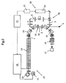
- Fig. 2 is a diagram showing the whole configuration of an X-ray generating device including a profile measuring device according to the invention.
- the X-ray generating device has an electron beam generating device 10 and a laser generating device 20.
- the electron beam generating device 10 has a function of accelerating an electron beam to generate a pulse electron beam 1 and transmitting the beam through a predetermined rectilinear orbit 2.
- the electron beam generating device 10 includes an RF electron gun 11, an ⁇ -magnet 12, an acceleration tube 13, a bending magnet 14, Q-magnets 15, a deceleration tube 16, and a beam dump 17.
- the RF electron gun 11 and the acceleration tube 13 are driven by a high-frequency power source 18 of an X-band (11.424 GHz). An orbit of the electron beam drawn from the RF electron gun 11 is changed by the ⁇ -magnet 12. The beam then enters the acceleration tube 13.
- the acceleration tube 13 is a small-sized X-band acceleration tube which accelerates the electron beam to generate a high-energy electron beam of preferably about 50 MeV. This electron beam is the pulse electron beam 1 of, for example, about 1 ⁇ s.
- the pulse electron beam 1 may be a multi-bunch pulse electron beam.
- the reason is that it is necessary to generate the electron beam of which the circulation time is longer than that (about 10 ns) of the laser beam in order to allow the circulating laser beam to collide with one mass of electrons more than once.
- the bending magnet 14 bends the orbit of the pulse electron beam 1 with a magnetic field, transmits the beam through the predetermined rectilinear orbit 2, and guides the transmitted pulse electron beam 1 to the beam dump 17.
- a convergence degree of the pulse electron beam 1 is adjusted by the Q-magnet 15.
- the pulse electron beam 1 is decelerated by the deceleration tube 16.
- the beam dump 17 traps the pulse electron beam 1 transmitted through the predetermined rectilinear orbit 2 to prevent leakage of radiation.
- a synchronization device 19 executes control so that the electron beam generating device 10 is synchronized with the laser generating device 20, a timing of the pulse electron beam 1 collides with that of a pulse laser beam 3 to be described later, and the pulse electron beam 1 collides with the pulse laser beam 3 at a collision point 2a on the predetermined rectilinear orbit 2.
- the pulse electron beam 1 of, for example, about 50 MeV, about 1 ⁇ s can be generated and transmitted through the predetermined rectilinear orbit 2.
- the laser generating device 20 has a laser device 21 and a variable beam expander 22, and has a function of generating a laser beam, expanding a diameter of the laser beam to a predetermined beam diameter, and irradiating the expanded laser beam.
- the laser device 21 uses an Nd-YAG laser having a wavelength of 1064 nm.
- the pulse laser beam 3 is not limited to this example, and ArF (wavelength of 193 nm), KrF (wavelength of 248 nm), XeCl (wavelength of 308 nm), XeF (wavelength of 351 nm) or Fe (wavelength of 157 nm) of an excimer laser, a third higher harmonic wave (wavelength of 355 nm), a fourth higher harmonic wave (wavelength of 266 nm) or a fifth higher harmonic wave (wavelength of 213 nm) of a YAG laser or the like may be used.
- the laser generating device 20 has an optical system for laser beam circulation 24, directs the pulse laser beam 3 into a circulation path 5 via a reflection mirror, traps the pulse laser beam 3 inside the circulation path 5, and repeatedly transmits the beam through a laser beam converging point 9 (not shown, see Fig. 4C for reference) in the circulation path.
- the laser beam may be a continuous laser beam and the laser device 21 may be a continuous laser device.
- the laser beam is the pulse laser beam 3 and the laser device 21 is a pulse laser device.
- the profile measuring device according to the invention is not limited to the above-described X-ray generating device and can be applied to other X-ray generating devices in which the electron beam and the laser beam are brought into frontal collision.
- the laser beam 3 is a pulse laser beam and the laser device 21 is a pulse laser device.
- the electron beam 1 in this example, pulse electron beam
- the laser beam 3 in this example, pulse laser beam
- the electron beam 1 and the laser beam 3 are controlled so as to be brought into frontal collision at the collision point 2a on the predetermined rectilinear orbit 2.
- the electron beam 1 is controlled in such a manner that the orbit of the electron beam 1 is controlled by the bending magnet 14, the convergence degree of the pulse electron beam 1 is controlled by the Q-magnets 15, and the arrival time of the pulse electron beam 1 to the collision point 2a is controlled by the synchronization device 19.
- the laser beam 3 is controlled in such a manner that the orbit of the laser beam 3 is controlled by the reflection mirror or the lateral position of a condenser, the converging position of the laser beam 3 is controlled by the axial position of the condenser, and the arrival time of the laser beam 3 to the collision point 2a is controlled by the synchronization device 19.
- the profile measuring device according to the invention is not limited to this control means and may allow other means to control the electron beam 1 and the laser beam 3.
- Figs. 3A to 3D shows collision modes of the electron beam 1 and the laser beam 3.
- Fig. 3A shows the state in which the focuses (beam waists) and the incident angles of the beams are not matched with each other
- Fig. 3B shows the state in which the focuses and the incident angles of the beams are matched with each other.
- focus the above focus and the beam waist are referred to as "focus”.
- Fig. 3C shows a state in which the beams do not simultaneously pass through the focus
- Fig. 3D shows a state in which the beams simultaneously passes through the focus.
- the basic concept of the invention is that, by moving the profile measuring device to be described later in a predetermined direction which substantially coincides with the axial directions of the beams, the positions and the distributions of the electron beam 1 and the laser beam 3 are measured over the whole range in which the device is movable.
- the beam waists (focuses) of the electron beam 1 and the laser beam 3 matched with each other can be directly measured, a position where the smallest beam size is measured can be decided as the beam waist (focus) to increase collision efficiency of the electron beam 1 and the laser beam 3.
- the electron beam and the laser beam are a pulse beam, it is necessary that the electron beam and the laser beam are simultaneously converged and pass through a position as the focus, as shown in Fig. 3D .
- An object of the device and method according to the invention is to easily realize the state of Fig. 3D .
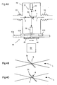
- Figs. 4A to 4C are diagrams showing a first embodiment of the profile measuring device according to the invention.
- the profile measuring device includes a profile measuring device 30, a moving device 40, and a profile creating device 50.
- a predetermined direction which substantially coincides with the axial directions of the electron beam 1 and the laser beam 3 is defined as an x direction.
- This x direction is the same as the rectilinear orbit 2 designed in Fig. 2 .
- the collision point 2a designed in the same drawing may be set as an origin.
- the axial directions of the electron beam 1 and the laser beam 3 may not be exactly matched with the x direction in the actual use.
- the profile measuring device 30 has a flat target plate 31, a first photodetector 32, and a second photodetector 33.
- the flat target plate 31 is preferably made of metal and disposed at a predetermined angle (for example, 45°) with respect to the above-described x direction.
- the target plate 31 may be preferably a target for optical transition radiation (for example, an aluminum vapor deposition mirror).
- the first photodetector 32 is a photomultiplier or a streak camera and continuously measures a two-dimensional profile of an optical transition radiation 6 generated by collision of the target plate 31 with the electron beam 1.
- the optical transition radiation 6 is emitted when the electron beam 1 passes through the target plate 31. Accordingly, by measuring the time direction distribution of this optical transition radiation with the first photodetector 32 (the photomultiplier or streak camera), it is possible to accurately know a timing at which the electron beam passes through the collision point.
- the second photodetector 33 measures a two-dimensional profile of the laser beam 3 reflected on the target plate 31. Since the target plate 31 (in this example, target for optical transition radiation) can be used as the reflection mirror for the laser beam 3, a timing at which the laser beam 3 passes through the collision point can be measured. These timings are compared with each other and properly combined to maximize the intensity of the X-ray.
- target plate 31 in this example, target for optical transition radiation
- a projection image generated by collision of the target plate 31 with the laser beam 3 can be measured while the two-dimensional profile of the optical transition radiation 6 generated by collision of the target plate 31 with the electron beam 1 is measured by the first photodetector 32.
- the second photodetector 33 is not necessary.
- reference numeral 52 denotes the vacuum chamber which houses the profile measuring device 30, and reference numerals 53 and 54 denote vacuum bellows.
- the vacuum bellows connect the vacuum chamber 52 integrally to a beam pipe to maintain a vacuum of a beam line and allow the vacuum chamber 52 to move in the x direction.
- the moving device 40 has a linear actuator 42 and a position detecting device 44.
- reference numeral 41a denotes a rail
- reference numerals 41b denote guides.
- the guides 41b are fixed to the vacuum chamber 52 and accurately directs the vacuum chamber 52 (and the profile measuring device 30 therein) in the x direction along the rail 41a.
- the linear actuator 42 is a linear electric motor or hydraulic cylinder and continuously moves in the x direction of the target plate 31. Further, the linear actuator 42 may include a rotation actuator and a linear mechanism (for example, rack pinion).
- the position detecting device 44 is, for example, a magnescale (registered trade name) and accurately detects the position in the x direction of the target plate 31 during movement with a resolution of preferably 10 ⁇ m or less.
- the profile measuring device 30 can continuously move in the x direction which substantially coincides with the axial directions of the electron beam 1 and the laser beam 3, and the position of the device in the x direction can be accurately detected.
- the optical transition radiation 6 is generated in an upper direction of this drawing.
- converting a temporal difference between the optical transition radiation 6 and the laser beam 3 into electric signals with the photomultiplier or the like, and measuring a temporal difference of the signals it is possible to know a temporal difference at the collision point between the electron beam 1 and the laser beam 3.
- delay time of the two photodetectors 32 and 33 is known, and it is necessary to exactly know whether a difference between optical paths from the target 31 to each of the photodetectors is none or the difference is accurately known.
- Fig. 4B schematically shows a generating state of the optical transition radiation 6.
- the optical transition radiation 6 is generated from a small area (for example, elliptical) corresponding to the focus on the metal target 31.
- the weak optical transition radiation 6 is generated from an area larger than the focus on the metal target 31.
- the focus of the electron beam 1 is positioned at an area where the strongest optical transition radiation 6 is generated from the smallest area.
- the profile creating device 50 is, for example, a PC (a computer) and creates temporal changes in three-dimensional profiles of the electron beam 1 and the laser beam 3 based on the cross-section profiles measured by the profile measuring device 30, the position of the profile measuring device in the x direction, and the oscillation timings of the beams.
- a PC a computer
- the temporal changes in the three-dimensional profiles obtained by the profile creating device 50 is stored in a storage device, outputted to a display device or a print device (not shown), and outputted to the above-described synchronization device 19.
- Fig. 5 is a diagram showing a second embodiment of the profile measuring device according to the invention.
- the profile measuring device 30 has the flat target plate 31, a single photodetector 34, first reflection mirror systems 35a and 35b, and second reflection mirror systems 36a and 36b.
- the flat target plate 31 is preferably made of metal and disposed at a predetermined angle (for example, 45°) with respect to the above-described x direction.
- the single photodetector 34 measures the two-dimensional profiles of the optical transition radiation 6 and the laser beam 3.
- the first reflection mirror systems 35a and 35b include two reflection mirrors 35a and 35b, and direct the optical transition radiation 6 generated by collision of the target plate 31 with the electron beam 1 to the photodetector 34.
- the second reflection mirror systems 36a and 36b include two reflection mirrors 36a and 36b, and direct the laser beam 3 reflected on the target plate 31 to the same photodetector 34. It is preferable that optical path lengths of the first reflection mirror systems 35a and 35b and the second reflection mirror systems 36a and 36b be accurately matched with each other.
- the one photodetector 34 is set and an optical path behind the metal target 31 is a proper optical transport system. According to this configuration, if a difference between the optical path of the laser beam 3 and the optical path of the optical transition radiation 6 become known or 0, the photodetector 34 can measure the difference by two pulse signals having a temporal difference therebetween.
- the single photodetector 34 can measure the two-dimensional profiles of the optical transition radiation 6 and the laser beam 3.
- the optical transition radiation 6 and the laser beam 3 may be simultaneously measured and separated from each other by a difference in wavelength, or may be independently measured.
- the cross-section profiles of the electron beam 1 and the laser beam 3 in the vicinity of the collision position (collision point 2a) where the electron beam 1 and the laser beam 3 are brought into frontal collision can be continuously measured.
- Fig. 6 is a diagram showing a third embodiment of the profile measuring device according to the invention.
- the profile measuring device 30 has the single photodetector 34, a first flat target plate 31a, and a second flat target plate 31b.
- the flat target plate 31a is preferably made of metal and disposed at a predetermined angle (for example, 45°) with respect to the above-described x direction.
- the single photodetector 34 measures the two-dimensional profiles of the optical transition radiation 6 and the laser beam 3.
- the second flat target plate 31b is disposed at a predetermined angle (for example, 45°) with respect to the predetermined x direction, and reflects the laser beam 3 to the same photodetector 34. That is, the first and second target plates 31a and 31b direct the optical transition radiation 6 and the laser beam 3 to the same photodetector 34.
- optical path lengths from the first and second target plates 31a and 31b to the photodetector 34 be accurately matched with each other.
- the moving device 40 continuously moves the first and second target plates 31a and 31b by a distance exceeding its length in the x direction to allow the positions in the x direction of the first and second target plates 31a and 31b during movement to be accurately detected.
- the optical path difference is caused only by the part of the metal targets.
- the second target plate 31b tilted at 45° in an opposite direction is installed on the back of the optical transition radiation target (first target plate 31a).
- the spatial positions of the laser beam and the electron beam are accurately adjusted in advance by a fluorescent screen, it can be detected which part of the target the laser beam or the electron beam passes through. Accordingly, the optical path difference between the laser beam and the optical transition radiation becomes known.
- the single photodetector 34 can measure the two-dimensional profiles of the optical transition radiation 6 and the laser beam 3 by the first and second target plates 31a and 31b.
- the optical transition radiation 6 and the laser beam 3 may be simultaneously measured and separated from each other by the difference in wavelength, or may be independently measured.
- the cross-section profiles of the electron beam 1 and the laser beam 3 in the vicinity of the collision position (the collision point 2a) where the electron beam 1 and the laser beam 3 are brought into frontal collision can be continuously measured.
- Fig. 7 is a diagram showing a fourth embodiment of the profile measuring device according to the invention.
- the profile measuring device 30 has a first profile measuring device 37 and a second profile measuring device 38.
- the first profile measuring device 37 is a beam profiler for electron beam and disposed at a right angle (vertical) with respect to the above-described x direction to directly measure the two-dimensional profile of the electron beam 1.
- the second profile measuring device 38 is a beam profiler for laser beam and disposed at a right angle with respect to the x direction to directly measure the two-dimensional profile of the laser beam 3.
- a shielding plate 39 may be inserted for shielding the electron beam and the laser beam.
- the moving device 40 continuously moves the first and second profile measuring devices 37 and 38 by a distance exceeding its length in the x direction to allow the positions in the x direction of the first and second profile measuring devices 37 and 38 during movement to be accurately detected.
- a profile measuring method according to the invention using the above-described profile measuring device according to the invention, includes a continuous moving step S1 and a profile creating step S2.
- the above-described profile measuring device 30 is continuously moved in the x direction which substantially coincides with the axial directions of the electron beam 1 and the laser beam 3 in the vicinity of the collision point 2a where the electron beam 1 and the laser beam 3 are brought into frontal collision.
- the temporal changes in the three-dimensional profiles of the electron beam 1 and the laser beam 3 are created based on a number of the cross-section profiles obtained in the continuous moving step S1, the position of the profile measuring device in the x direction, and the oscillation timings of the beams.
- cross-section profiles of the electron beam 1 and the laser beam 3 measured by the profile measuring device 30 according to the invention are momentary cross-section profiles. Accordingly, only from these single profiles, the focuses and the incident angles of the beams cannot be measured.
- the linear actuator 42 continuously move the target plate 31, the first profile measuring device 37, and the second profile measuring device 38 by a distance exceeding its length in the x direction. From a number of the cross-section profiles continuously obtained at that time, the three-dimensional profiles of the electron beam 1 and the laser beam 3 are created.
- the three-dimensional profiles of the beams cannot be quickly and simultaneously measured. Accordingly, in relation to the oscillation timings of the beams, a number of profile data is stored in the storage device (not shown), and consolidated to create the temporal changes in the three-dimensional profiles of the electron beam 1 and the laser beam 3.
- the focuses and the incident angles of the beams can be then measured, as shown in Fig. 3A .
- the focus and the incident angle of the electron beam 1 are difficult to adjust in general. Accordingly, by adjusting the position of the reflection mirror for the laser beam 3 or the condenser, the focuses and the incident angles of the beams are matched with each other, as shown in Fig. 3B .
- the arrival time of the pulse electron beam 1 to the collision point 2a or the arrival time of the laser beam 3 to the collision point 2a is controlled by the synchronization device 19. Therefore, as shown in Fig. 3D , control can be performed so that the electron beam 1 and the laser beam 3 simultaneously pass through the focus.
- the invention by accurately measuring four-dimensional parameters (three-dimensional space and temporal axis) of the electron beam 1 and the laser beam 3 in the vicinity of the collision point in the X-ray generating device using the collision of the electron beam and the laser beam, a complete overlap of the electron beam and the laser beam in a space of four dimensions is realized, and generation of X-ray is maximized.
- one profile measuring device has been installed at a point which is estimated as the collision point.
- the positions and profiles of the beams at the position of the profile measuring device can be measured.
- the beam waists (focuses) of the electron beam and the laser beam cannot be specified.
- it is necessary to adjust a beam optical system by: assuming the installation position of the profile measuring device as the focus position; and changing a convergence strength of a quadrupole magnet so as to minimize the profiles on the profile measuring device.
- the electron beam can be allowed to collide with the laser beam as planned, and the X-ray can be generated with the high collision efficiency.
- M2 of the laser beam and the emittance and Twiss parameter of the electron beam which are important to calculate the intensity of the X-ray at the time of collision, can be directly measured at the collision point without breaking down the optical system for the electron beam or the laser beam.
- the electron beam is measured according to a Q-scan method.
- a distance error from the Q magnet to the profile measuring device, and the K value there are causes which produce an error in measurement, such as hysteresis of an electromagnetic material.
- the profile measuring device is moved with, for example, a several tens of micrometer accuracy and the profiles at each position are measured, the above problem is not generated.
- Non-Patent Document 2 when a monitor is provided at each of three predetermined positions, it is impossible to completely trace the position of focus and the pulse state. For example, the stationary monitor cannot grasp the position of the focus in a certain state (a distinction of an apparent focus and the focus).
- the invention provides a device having a mechanism capable of confirming the states of the laser beam and the electron beam at each arbitrary position per a unit of 10 ⁇ m, and easily solves the above problems.
Landscapes
- Physics & Mathematics (AREA)
- Engineering & Computer Science (AREA)
- Optics & Photonics (AREA)
- Plasma & Fusion (AREA)
- Measurement Of Radiation (AREA)
- X-Ray Techniques (AREA)
Claims (7)
- Vorrichtung zum Messen von Profilen eines Elektronenstrahls (1) und eines Laserstrahls (3), die umfasst:eine Vakuumkammer (52), die eine Profilmessvorrichtung (30) zum Messen von Querschnittsprofilen der Strahlen in der Nähe einer Kollisionsposition aufnimmt, an der der Elektronenstrahl (1) und der Laserstrahl (3) zu frontaler Kollision gebracht werden; undeine Bewegungsvorrichtung (40), mit der die Profilmessvorrichtung (30) kontinuierlich bewegt wird, indem die Vakuumkammer (52) in einer vorgegebenen Richtung (x) bewegt wird, die im Wesentlichen mit den axialen Richtungen der Strahlen übereinstimmt;wobei die Bewegungsvorrichtung ein Linear-Stellglied (42), mit dem die Profilmessvorrichtung kontinuierlich in der vorgegebenen Richtung bewegt wird, und eine Positionserfassungsvorrichtung (44) enthält, mit der die Position der Profilmessvorrichtung in der vorgegebenen Richtung erfasst wird.
- Vorrichtung zum Messen von Profilen eines Elektronenstrahls und eines Laserstrahls nach Anspruch 1, die des Weiteren eine Profilerzeugungsvorrichtung (50) umfasst, mit der temporäre Änderungen an dreidimensionalen Profilen der Strahlen auf Basis der von der Profilmessvorrichtung gemessenen Querschnittsprofile, der Position der Profilmessvorrichtung in der vorgegebenen Richtung und der Oszillations-Zeitpunkte der Strahlen vorgenommen werden.
- Vorrichtung zum Messen von Profilen eines Elektronenstrahls und eines Laserstrahls nach Anspruch 1,
wobei die Profilmessvorrichtung eine flache Ziel-Platte (31), die in einem vorgegebenen Winkel in Bezug auf die vorgegebene Richtung angeordnet ist, einen ersten Fotodetektor (32) zum Messen eines zweidimensionalen Profils einer optischen Übergangsstrahlung, die durch die Kollision der Ziel-Platte mit dem Elektronenstrahl erzeugt wird, und einen zweiten Fotodetektor (33) zum Messen eines zweidimensionalen Profils des an der Ziel-Platte reflektierten Laserstrahls enthält. - Vorrichtung zum Messen von Profilen eines Elektronenstrahls und eines Laserstrahls nach Anspruch 1,
wobei die Profilmessvorrichtung eine flache Ziel-Platte (31), die in einem vorgegebenen Winkel in Bezug auf die vorgegebene Richtung angeordnet ist, einen einzelnen Fotodetektor (34) zum Messen zweidimensionaler Profile einer optischen Übergangsstrahlung sowie des Laserstrahls, ein erstes Reflektions-Spiegelsystem (35a, 35b), mit dem die durch Kollision der Ziel-Platte mit dem Elektrodenstrahl erzeugte optische Übergangsstrahlung zu dem Fotodetektor gerichtet wird, und ein zweites Reflektions-Spiegelsystem (36a, 36b) enthält, mit dem der an der Ziel-Platte reflektierte Laserstrahl zu dem Fotodetektor gerichtet wird. - Vorrichtung zum Messen von Profilen eines Elektronenstrahls und eines Laserstrahls nach Anspruch 1,
wobei die Profilmessvorrichtung einen einzelnen Fotodetektor (34) zum Messen zweidimensionaler Profile einer optischen Übergangsstrahlung sowie des Laserstrahls, eine erste flache Ziel-Platte (31a), die in einem vorgegebenen Winkel in Bezug auf die vorgegebene Richtung angeordnet ist und die durch Kollision mit dem Elektronenstrahl erzeugte optische Übergangsstrahlung zu dem Fotodetektor richtet, sowie eine zweite Ziel-Platte (31 b) enthält, die in einem vorgegebenen Winkel in Bezug auf die vorgegebene Richtung angeordnet ist und den Laserstrahl zu dem Fotodetektor reflektiert. - Vorrichtung zum Messen von Profilen eines Elektronenstrahls und eines Laserstrahls nach Anspruch 1,
wobei die Profilmessvorrichtung eine erste Profilmessvorrichtung (37), die in einem rechten Winkel in Bezug auf die vorgegebene Richtung angeordnet ist und ein zweidimensionales Profil des Elektronenstrahls misst, sowie eine zweite Profilmessvorrichtung (38) enthält, die in einem rechten Winkel in Bezug auf die vorgegebene Richtung angeordnet ist und ein zweidimensionales Profil des Laserstrahls misst. - Verfahren zum Messen von Profilen eines Elektronenstrahls (1) und eines Laserstrahls (3), wobei das Verfahren umfasst:einen Schritt kontinuierlicher Bewegung, in dem eine Vakuumkammer (52), die eine Profilmessvorrichtung (30) aufnimmt, kontinuierlich bewegt wird, um kontinuierlich Querschnittsprofile der Strahlen in der Nähe einer Kollisionsposition zu messen, an der der Elektronenstrahl und der Laserstrahl zu frontaler Kollision in einer vorgegebenen Richtung gebracht werden, die im Wesentlichen mit den axialen Richtungen der Strahlen übereinstimmt; undeinen Schritt zum Erzeugen von Profilen, in dem temporäre Änderungen an dreidimensionalen Profilen der Strahlen auf Basis der in dem Schritt kontinuierlicher Bewegung gewonnenen Querschnittsprofile, der Position der Profilmessvorrichtung in der vorgegebenen Richtung und der Oszillations-Zeitpunkte der Strahlen vorgenommen werden.
Applications Claiming Priority (2)
| Application Number | Priority Date | Filing Date | Title |
|---|---|---|---|
| JP2006080383A JP4963368B2 (ja) | 2006-03-23 | 2006-03-23 | 電子ビーム及びレーザービームのプロファイル測定装置及び方法 |
| PCT/JP2007/054410 WO2007108320A1 (ja) | 2006-03-23 | 2007-03-07 | 電子ビーム及びレーザービームのプロファイル測定装置及び方法 |
Publications (3)
| Publication Number | Publication Date |
|---|---|
| EP1998601A1 EP1998601A1 (de) | 2008-12-03 |
| EP1998601A4 EP1998601A4 (de) | 2011-02-23 |
| EP1998601B1 true EP1998601B1 (de) | 2014-03-05 |
Family
ID=38522353
Family Applications (1)
| Application Number | Title | Priority Date | Filing Date |
|---|---|---|---|
| EP07737924.6A Not-in-force EP1998601B1 (de) | 2006-03-23 | 2007-03-07 | Vorrichtung und verfahren zur messung des profils von elektronischen strahlen und laserstrahlen |
Country Status (4)
| Country | Link |
|---|---|
| US (1) | US7817288B2 (de) |
| EP (1) | EP1998601B1 (de) |
| JP (1) | JP4963368B2 (de) |
| WO (1) | WO2007108320A1 (de) |
Families Citing this family (9)
| Publication number | Priority date | Publication date | Assignee | Title |
|---|---|---|---|---|
| JP5088074B2 (ja) | 2007-10-01 | 2012-12-05 | 日産自動車株式会社 | 駐車支援装置及び方法 |
| JP5454837B2 (ja) * | 2008-02-05 | 2014-03-26 | 株式会社Ihi | 硬x線ビーム走査装置および方法 |
| JP2011198568A (ja) * | 2010-03-18 | 2011-10-06 | Ihi Corp | X線発生装置 |
| WO2012109340A1 (en) * | 2011-02-08 | 2012-08-16 | Atti International Services Company, Inc. | Electron beam profile measurement system and method with "moms" |
| JP5564449B2 (ja) * | 2011-02-16 | 2014-07-30 | 富士フイルム株式会社 | 光音響撮像装置、それに用いられるプローブユニットおよび光音響撮像装置の作動方法 |
| JP5502777B2 (ja) * | 2011-02-16 | 2014-05-28 | 富士フイルム株式会社 | 光音響撮像装置およびそれに用いられるプローブユニット |
| JP5113287B2 (ja) * | 2011-11-01 | 2013-01-09 | 株式会社Ihi | X線計測装置及びx線計測方法 |
| CN103376460B (zh) * | 2012-04-28 | 2015-07-29 | 中国科学院电子学研究所 | 一种强流电子注分析仪的电子注截面测量系统 |
| CN112558136A (zh) * | 2019-09-10 | 2021-03-26 | 南京邮电大学 | 强激光脉冲与高能电子对撞的三维立体探测的处理方法 |
Family Cites Families (6)
| Publication number | Priority date | Publication date | Assignee | Title |
|---|---|---|---|---|
| US4602272A (en) * | 1984-11-13 | 1986-07-22 | Rca Corporation | Electron beam intensity profile measuring system and method |
| US4797619A (en) * | 1987-03-13 | 1989-01-10 | Eg&G Gamma Scientific Incorporated | Method and apparatus for measuring spatial profiles of energy beams |
| JPH10290053A (ja) | 1997-02-12 | 1998-10-27 | Sony Corp | 光学装置及び光短波長化方法 |
| US6687333B2 (en) * | 1999-01-25 | 2004-02-03 | Vanderbilt University | System and method for producing pulsed monochromatic X-rays |
| JP3497447B2 (ja) | 2000-05-29 | 2004-02-16 | 住友重機械工業株式会社 | X線発生装置及び発生方法 |
| JP3810716B2 (ja) * | 2002-08-01 | 2006-08-16 | 住友重機械工業株式会社 | X線発生装置及び発生方法 |
-
2006
- 2006-03-23 JP JP2006080383A patent/JP4963368B2/ja not_active Expired - Fee Related
-
2007
- 2007-03-07 WO PCT/JP2007/054410 patent/WO2007108320A1/ja not_active Ceased
- 2007-03-07 EP EP07737924.6A patent/EP1998601B1/de not_active Not-in-force
- 2007-03-07 US US12/162,912 patent/US7817288B2/en not_active Expired - Fee Related
Also Published As
| Publication number | Publication date |
|---|---|
| EP1998601A1 (de) | 2008-12-03 |
| US7817288B2 (en) | 2010-10-19 |
| WO2007108320A1 (ja) | 2007-09-27 |
| EP1998601A4 (de) | 2011-02-23 |
| JP2007257986A (ja) | 2007-10-04 |
| JP4963368B2 (ja) | 2012-06-27 |
| US20090051937A1 (en) | 2009-02-26 |
Similar Documents
| Publication | Publication Date | Title |
|---|---|---|
| EP1998601B1 (de) | Vorrichtung und verfahren zur messung des profils von elektronischen strahlen und laserstrahlen | |
| JP5588106B2 (ja) | 光アンジュレータを使用する高効率単色x線源 | |
| Cline et al. | First observation of acceleration of electrons by a laser in a vacuum | |
| EP2164307B1 (de) | Vorrichtung und verfahren zur anpassung der kollisionszeit zwischen elektronenstrahlen und laserlicht | |
| CN109041393A (zh) | 一种超快硬x射线源的产生装置及方法 | |
| EP2164306B1 (de) | Vorrichtung und verfahren zur erzeugung von röntgenstrahlen mit hoher helligkeit | |
| Chaleil et al. | Inverse Compton scattering X-ray source yield optimization with a laser path folding system inserted in a pre-existent RF linac | |
| US11715617B2 (en) | Method and apparatus for synchronizing charged particle pulses with light pulses | |
| Liu et al. | Micrometer accuracy method for small-scale laser focal spot centroid measurement | |
| US7724876B2 (en) | Multi-color X-ray generator | |
| Vashchenko | Transverse phase space studies with the new CDS booster cavity at PITZ | |
| JP2009016119A (ja) | X線発生装置の波長変更装置および方法 | |
| JP2006344731A (ja) | レーザー光周回装置及びレーザー光周回方法 | |
| JP5454837B2 (ja) | 硬x線ビーム走査装置および方法 | |
| CN116359809B (zh) | 一种实时原位在线无接触式测量第一壁材料表面磁场的方法 | |
| JP5113287B2 (ja) | X線計測装置及びx線計測方法 | |
| JP4879102B2 (ja) | X線計測装置及びx線計測方法 | |
| Fittinghoff et al. | PLEIADES: a subpicosecond Thomson x-ray source for ultrafast materials probing | |
| Chen et al. | Proposal for a study of laser acceleration of electrons using micrograting structures at ATF (Phase 1) | |
| 高凯 et al. | Online plasma diagnostics of a laser-produced plasma | |
| Kim | Fast electron generation using PW-class PEARL facility |
Legal Events
| Date | Code | Title | Description |
|---|---|---|---|
| PUAI | Public reference made under article 153(3) epc to a published international application that has entered the european phase |
Free format text: ORIGINAL CODE: 0009012 |
|
| 17P | Request for examination filed |
Effective date: 20080703 |
|
| AK | Designated contracting states |
Kind code of ref document: A1 Designated state(s): DE FR GB |
|
| RIN1 | Information on inventor provided before grant (corrected) |
Inventor name: ISHIDA, DAISUKE Inventor name: SAKAMOTO, FUMITO Inventor name: KANEKO, NAMIO Inventor name: UESAKA, MITSURU Inventor name: DOBASHI, KATSUHIRO Inventor name: NOSE, HIROYUKI |
|
| DAX | Request for extension of the european patent (deleted) | ||
| RBV | Designated contracting states (corrected) |
Designated state(s): DE FR GB |
|
| A4 | Supplementary search report drawn up and despatched |
Effective date: 20110120 |
|
| 17Q | First examination report despatched |
Effective date: 20120314 |
|
| GRAP | Despatch of communication of intention to grant a patent |
Free format text: ORIGINAL CODE: EPIDOSNIGR1 |
|
| INTG | Intention to grant announced |
Effective date: 20130903 |
|
| RIN1 | Information on inventor provided before grant (corrected) |
Inventor name: DOBASHI, KATSUHIRO Inventor name: KANEKO, NAMIO Inventor name: NOSE, HIROYUKI Inventor name: UESAKA, MITSURU Inventor name: ISHIDA, DAISUKE Inventor name: SAKAMOTO, FUMITO |
|
| GRAS | Grant fee paid |
Free format text: ORIGINAL CODE: EPIDOSNIGR3 |
|
| GRAA | (expected) grant |
Free format text: ORIGINAL CODE: 0009210 |
|
| RAP1 | Party data changed (applicant data changed or rights of an application transferred) |
Owner name: IHI CORPORATION Owner name: THE UNIVERSITY OF TOKYO |
|
| AK | Designated contracting states |
Kind code of ref document: B1 Designated state(s): DE FR GB |
|
| REG | Reference to a national code |
Ref country code: GB Ref legal event code: FG4D |
|
| REG | Reference to a national code |
Ref country code: DE Ref legal event code: R096 Ref document number: 602007035352 Country of ref document: DE Effective date: 20140417 |
|
| REG | Reference to a national code |
Ref country code: DE Ref legal event code: R097 Ref document number: 602007035352 Country of ref document: DE |
|
| PLBE | No opposition filed within time limit |
Free format text: ORIGINAL CODE: 0009261 |
|
| STAA | Information on the status of an ep patent application or granted ep patent |
Free format text: STATUS: NO OPPOSITION FILED WITHIN TIME LIMIT |
|
| 26N | No opposition filed |
Effective date: 20141208 |
|
| REG | Reference to a national code |
Ref country code: DE Ref legal event code: R097 Ref document number: 602007035352 Country of ref document: DE Effective date: 20141208 |
|
| REG | Reference to a national code |
Ref country code: FR Ref legal event code: PLFP Year of fee payment: 10 |
|
| PGFP | Annual fee paid to national office [announced via postgrant information from national office to epo] |
Ref country code: DE Payment date: 20160302 Year of fee payment: 10 |
|
| PGFP | Annual fee paid to national office [announced via postgrant information from national office to epo] |
Ref country code: GB Payment date: 20160302 Year of fee payment: 10 Ref country code: FR Payment date: 20160208 Year of fee payment: 10 |
|
| REG | Reference to a national code |
Ref country code: DE Ref legal event code: R119 Ref document number: 602007035352 Country of ref document: DE |
|
| GBPC | Gb: european patent ceased through non-payment of renewal fee |
Effective date: 20170307 |
|
| REG | Reference to a national code |
Ref country code: FR Ref legal event code: ST Effective date: 20171130 |
|
| PG25 | Lapsed in a contracting state [announced via postgrant information from national office to epo] |
Ref country code: DE Free format text: LAPSE BECAUSE OF NON-PAYMENT OF DUE FEES Effective date: 20171003 Ref country code: FR Free format text: LAPSE BECAUSE OF NON-PAYMENT OF DUE FEES Effective date: 20170331 |
|
| PG25 | Lapsed in a contracting state [announced via postgrant information from national office to epo] |
Ref country code: GB Free format text: LAPSE BECAUSE OF NON-PAYMENT OF DUE FEES Effective date: 20170307 |