EP1998555A2 - Kameramodul - Google Patents
Kameramodul Download PDFInfo
- Publication number
- EP1998555A2 EP1998555A2 EP08104169A EP08104169A EP1998555A2 EP 1998555 A2 EP1998555 A2 EP 1998555A2 EP 08104169 A EP08104169 A EP 08104169A EP 08104169 A EP08104169 A EP 08104169A EP 1998555 A2 EP1998555 A2 EP 1998555A2
- Authority
- EP
- European Patent Office
- Prior art keywords
- yoke
- holder
- coil
- magnets
- camera module
- Prior art date
- Legal status (The legal status is an assumption and is not a legal conclusion. Google has not performed a legal analysis and makes no representation as to the accuracy of the status listed.)
- Granted
Links
- 230000003287 optical effect Effects 0.000 claims abstract description 13
- 230000004907 flux Effects 0.000 claims description 21
- 239000000696 magnetic material Substances 0.000 claims description 3
- 230000009467 reduction Effects 0.000 description 6
- 230000001413 cellular effect Effects 0.000 description 3
- 230000000694 effects Effects 0.000 description 1
- 238000003384 imaging method Methods 0.000 description 1
- 230000003993 interaction Effects 0.000 description 1
- 230000004048 modification Effects 0.000 description 1
- 238000012986 modification Methods 0.000 description 1
- 230000002940 repellent Effects 0.000 description 1
- 239000005871 repellent Substances 0.000 description 1
Images

Classifications
-
- G—PHYSICS
- G03—PHOTOGRAPHY; CINEMATOGRAPHY; ANALOGOUS TECHNIQUES USING WAVES OTHER THAN OPTICAL WAVES; ELECTROGRAPHY; HOLOGRAPHY
- G03B—APPARATUS OR ARRANGEMENTS FOR TAKING PHOTOGRAPHS OR FOR PROJECTING OR VIEWING THEM; APPARATUS OR ARRANGEMENTS EMPLOYING ANALOGOUS TECHNIQUES USING WAVES OTHER THAN OPTICAL WAVES; ACCESSORIES THEREFOR
- G03B30/00—Camera modules comprising integrated lens units and imaging units, specially adapted for being embedded in other devices, e.g. mobile phones or vehicles
-
- H—ELECTRICITY
- H04—ELECTRIC COMMUNICATION TECHNIQUE
- H04N—PICTORIAL COMMUNICATION, e.g. TELEVISION
- H04N23/00—Cameras or camera modules comprising electronic image sensors; Control thereof
- H04N23/50—Constructional details
- H04N23/55—Optical parts specially adapted for electronic image sensors; Mounting thereof
-
- H—ELECTRICITY
- H04—ELECTRIC COMMUNICATION TECHNIQUE
- H04N—PICTORIAL COMMUNICATION, e.g. TELEVISION
- H04N23/00—Cameras or camera modules comprising electronic image sensors; Control thereof
- H04N23/57—Mechanical or electrical details of cameras or camera modules specially adapted for being embedded in other devices
-
- G—PHYSICS
- G03—PHOTOGRAPHY; CINEMATOGRAPHY; ANALOGOUS TECHNIQUES USING WAVES OTHER THAN OPTICAL WAVES; ELECTROGRAPHY; HOLOGRAPHY
- G03B—APPARATUS OR ARRANGEMENTS FOR TAKING PHOTOGRAPHS OR FOR PROJECTING OR VIEWING THEM; APPARATUS OR ARRANGEMENTS EMPLOYING ANALOGOUS TECHNIQUES USING WAVES OTHER THAN OPTICAL WAVES; ACCESSORIES THEREFOR
- G03B5/00—Adjustment of optical system relative to image or object surface other than for focusing
-
- G—PHYSICS
- G03—PHOTOGRAPHY; CINEMATOGRAPHY; ANALOGOUS TECHNIQUES USING WAVES OTHER THAN OPTICAL WAVES; ELECTROGRAPHY; HOLOGRAPHY
- G03B—APPARATUS OR ARRANGEMENTS FOR TAKING PHOTOGRAPHS OR FOR PROJECTING OR VIEWING THEM; APPARATUS OR ARRANGEMENTS EMPLOYING ANALOGOUS TECHNIQUES USING WAVES OTHER THAN OPTICAL WAVES; ACCESSORIES THEREFOR
- G03B7/00—Control of exposure by setting shutters, diaphragms or filters, separately or conjointly
- G03B7/04—Control effected by hand adjustment of a member that senses indication of a pointer of a built- in light-sensitive device, e.g. by restoring point to a fixed associated reference mark
-
- G—PHYSICS
- G03—PHOTOGRAPHY; CINEMATOGRAPHY; ANALOGOUS TECHNIQUES USING WAVES OTHER THAN OPTICAL WAVES; ELECTROGRAPHY; HOLOGRAPHY
- G03B—APPARATUS OR ARRANGEMENTS FOR TAKING PHOTOGRAPHS OR FOR PROJECTING OR VIEWING THEM; APPARATUS OR ARRANGEMENTS EMPLOYING ANALOGOUS TECHNIQUES USING WAVES OTHER THAN OPTICAL WAVES; ACCESSORIES THEREFOR
- G03B2205/00—Adjustment of optical system relative to image or object surface other than for focusing
- G03B2205/0053—Driving means for the movement of one or more optical element
- G03B2205/0069—Driving means for the movement of one or more optical element using electromagnetic actuators, e.g. voice coils
Definitions
- This invention relates to a camera module, and more specifically to a camera module that can be used in small-sized electronic apparatuses such as digital cameras, camera-equipped cellular phones and the like.
- a camera module having a function of displacing a lens unit in a direction of an optical axis of the lens unit is used in relatively small-sized digital cameras, camera-equipped cellular phones and the like.
- This function is used for providing an autofocus function and/or zoom function, and is achieved by an interaction between a magnetic field generated by an electrical current flowing in a coil and a magnetic field generated by a yoke and magnets provided on the yoke.
- camera modules to be mounted in camera-equipped cellular phones are required to further reduce size and shape thereof.
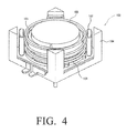
- FIG. 4 shows an actuator assembly for providing an autofocus function used in a conventional camera module.
- the actuator assembly 100 includes a holder 103 which houses a lens unit (not shown in the drawing), a coil 101 wound around the holder 103, a base 104 formed into a roughly square shape having four corner posts near the four corner thereof, four magnets 102 respectively arranged near the four corner posts of the base 104, and a spring 105 for resiliently supporting the holder 103.
- the actuator assembly 100 by supplying an electrical current to the coil 101 provided on the holder 103, a repellent force is generated by the magnetic fields provided by the four magnets 102 and the coil 101. Further, by utilizing a spring force of the spring 105, the holder 103 can be displaced up and down directions in the figure to carry out the autofocus function.
- the four magnets 102 are arranged on the corners of the roughly square-shaped base 104. Therefore, when the entire size of the camera is to be reduced, there is a problem in that sufficient thickness of each of the magnets 102 cannot be secured. This is because if the thickness of each magnet 102 is reduced, the distance between the N pole and the S pole in each magnet is shortened, thus resulting in a reduced magnetic force.
- the reduced magnetic field intensity due to the reduced size of each magnet is compensated by the provision of the spring 105.
- the entire size of the camera module is to be further reduced, there arises another problem in that it becomes difficult to secure a space for providing the spring 105.
- the present invention has been made in view of the problems described above, and therefore it is an object of the present invention to provide a camera module that can provide a sufficient driving force of a holder even in the case where the entire size of the camera module is reduced.
- a camera module which comprises:
- the coil is formed into a roughly cylindrical shape having two opposite outer circumferential flat surfaces
- each of the main magnets has the triangle block shape, it is possible to lengthen the distances between the N pole and the S pole in each magnet, and further they can effectively utilize the spaces of the corner portions of the yoke.
- the camera module further comprises a magnetic field correcting magnet, wherein the magnetic field correcting magnet is arranged so as to provide a magnetic flux in a vertical direction with respect to a direction of a magnetic flux of the main magnets and auxiliary magnets so that the magnetic flux of the main magnets and auxiliary magnets is directed toward the coil.
- the base is made of a magnetic material, and the magnetic field correcting magnet is formed by magnetizing at least a part of the base.
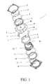
- An actuator assembly 1 of a camera module includes: a lens unit which constitutes an optical system of the camera module (not shown in the drawings) ; a holder 10 which houses the lens unit therein and is displaceable along the optical axis direction of the camera module, the holder 10 having a roughly cylindrical shape having upper and lower cylindrical end portions; a coil 9 provided on the holder 10; and a yoke 6, four main magnets 7 and two flat plate-shaped auxiliary magnets 8 which provide a magnetic field to the coil 9.
- the yoke 6 has a roughly rectangular and relatively thin box shape of which bottom side is opened so that the yoke 6 is defined by four side wall portions 6b and a top plate portion 6e, and the yoke 6 also has an opening 6c formed in the top plate portion 6e for receiving the holder 10 and four corner portions 6a inside thereof.
- the actuator assembly 1 of the camera module further includes an upper leaf spring 5 and a lower leaf spring 12 for supporting the holder 10; and a base 14 which supports the yoke 6 and the lower leaf spring 12.
- the coil 9 is formed into a roughly cylindrical shape having two opposite outer circumferential flat surfaces 9a.
- Each of the four main magnets 7 has a triangle block shape and they are respectively arranged at the four corner portions 6a inside the yoke 6.
- the two auxiliary magnets 8 are respectively arranged on a pair of the opposite side wall portions 6b of the yoke 6 so as to face the corresponding outer circumferential flat surfaces 9a of the coil 9, respectively.
- the holder 10 which houses a barrel (not shown) holding the lens unit therein is provided in a space defined between a cover 2 and the base 14 so that the holder 10 is displaceable in the direction of the optical axis of the lens unit.
- An inner annular portion of the upper leaf spring 5 and an inner annular portion of the lower leaf spring 12 are respectively attached to the upper and lower cylindrical end portions of the holder 10, and an outer annular portion of the upper leaf spring 5 is attached to the top plate portion 6e of the yoke 6 and an outer annular portion of the lower leaf spring 12 is attached to the base 14.
- the inner annular portion of the upper leaf spring 5 is resiliently supported by the outer annular portion of the upper leaf spring 5 through bridge portions provided therebetween
- the inner annular portion of the lower leaf spring 12 is resiliently supported by the outer annular portion of the lower leaf spring 12 through bridge portions provided therebetween.
- the yoke 6, the main magnets 7 and the auxiliary magnets 8 generate a magnetic field.
- the coil 9 is disposed in the magnetic field generated by the yoke 6, the main magnets 7 and the auxiliary magnets 8.
- the coil 9 is provided on the outer periphery of the holder 10 so that the coil 9 is positioned in a space between a pair of arch-shaped inner wall portions 6d of the yoke 6 provided along the outer periphery of the opening 6c and the main magnets 7 and the auxiliary magnets 8 in a state that the holder 10 is inserted into the opening 6c.
- the holder 10 can be displaced in a direction of the optical axis of the lens unit by supplying a current to the coil 9.
- a component denoted by the reference numeral 3 is a stopper provided on the upper side of the inner annular portion of the upper leaf spring 5
- a component denoted by the reference numeral 4 is a first annular plate provided on the upper side of the outer annular portion of the upper leaf spring 5.
- a component denoted by the reference numeral 11 is a second annular plate provided on the outer annular portion of the lower leaf spring 12, and a component denoted by the reference numeral 13 is a flexible printed circuit board for supplying a current to the coil 9.
- the yoke 6 is formed into a roughly rectangular and relatively thin box shape of which bottom side is opened so that the yoke 6 is defined by the four side wall portions 6b and the top plate portion 6e. As a result, the four corner portions 6a are defined inside thereof. Further, the yoke 6 has the opening 6c formed in the top plate portion 6e for receiving the holder 10.
- the yoke 6 also includes inside thereof the pair of arch-shaped inner wall portions 6d provided along the outer periphery of the opening 6c, wherein the pair of arch-shaped inner wall portions 6d of the yoke 6 are arranged so that two gaps are created between the adjacent end portions of the inner wall portions 6d.
- Each of the four main magnets 7 is formed to have a triangle block shape (the triangle block having an equilateral triangle shape in its cross section). These four main magnets 7 are respectively arranged at the four corner portions 6a inside the yoke 6.
- the two flat plate-shapeed auxiliary magnets 8 are respectively arranged on the concave portions of the opposite side wall portions 6b of the yoke 6 as illustrated in FIG. 2 .
- the coil 9 supported by the holder 10 is positioned in a space between the pair of arc-shaped inner wall portions 6d and the main magnets 7 and the auxiliary magnets 8 in a state that the holder 10 is inserted into the opening 6c of the yoke 6.
- the coil 9 is formed into a cylindrical coil which has the two opposite outer circumferential flat surfaces 9a.
- the coil 9 provided on the holder 10 is disposed in the space between the pair of arch-shaped inner wall portions 6d of the yoke 6 and the main magnets 7 and the auxiliary magnets 8 so that the two opposite outer circumferential flat surfaces 9a of the coil 9 face the auxiliary magnets 8, respectively, in a state that the holder 10 is inserted into the opening 6c of the yoke 6. in this state, the two opposite outer circumferential flat surfaces 9a of the coil 9 are also located at positions of the gaps created between the adjacent end portions of the inner wall portions 6d of the yoke 6.
- each of the four main magnets 7 formed into the triangle block shape is magnetised so that its inner side portion (that is, a side of each magnet 7 facing the coil 9) becomes an N pole and its outer corner side becomes an S pole. Since each of the main magnets 7 has such a triangle block shape (that is, an equilateral triangle shape in its cross section), it is possible to effectively utilize the spaces of the corner portions 6a of the yoke 6. Further, in each main magnet 7 having such a triangle block shape, the distance between the inner side portion of the N pole and the outer corner portion of the S pole can be made to be relatively long.
- each of the main magnets 7 can secure a stable magnetic field of which magnetic force is difficult to be reduced even where a temperature of the camera module is raised.
- an inner side portion (facing the corresponding outer circumferential flat surface 9a of the coil 9) is magnetized to be an N pole and an outer side portion adjacent to the yoke 6 is magnetized to be an S pole.
- the two auxiliary magnets 8 are arranged so as to face the corresponding outer circumferential flat surfaces 9a of the coil 9, respectively.
- the entire surfaces of the inner side portions (which are magnetized to be an N pole) of the auxiliary magnets 8 are arranged in a spaced manner at a predetermined interval from the entire surfaces of the outer circumferential flat surfaces 9a of the coil 9.
- magnetic fluxes which are generated by the auxiliary magnets 8 can pass through the coil 9 over a wide range of the outer circumferential flat surfaces 9a of the coil 9, thereby allowing magnetic forces of the auxiliary magnets 8 to be effectively exerted on the coil 9.
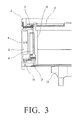
- the base 14 is formed by magnetizing a magnetic material having a predetermined shape as a base and serves as a magnetic field correcting magnet of the present invention. As described in FIG. 3 , the top surface side of the base 14 is magnetized to be an N pole and the bottom surface side of the base 14 is magnetized to be an S pole. A magnetic flux from the N poles of the main magnets 7 and auxiliary magnets 8 is generated in a horizontal direction, whereas a magnetic flux from the N pole of the top surface side of the base 14 is generated in a vertical direction.
- the magnetic flux of the N pole of the base 14 which is the magnetic field correcting magnet acts against the magnetic flux of the N poles of the main magnets 7 and auxiliary magnets 8 repulsively, whereby the direction of the magnetic flux of the main magnets 7 and auxiliary magnets 8 is forcedly directed in a direction away from the base 14. That is to say, the direction of the magnetic flux of the main magnets 7 and auxiliary magnets 8 is forcedly directed toward the coil 9 as is understood from FIG. 3 . Therefore, the magnetic forces of the main magnets 7 and auxiliary magnets 8 can be effectively exerted on the coil 9. Further, since the magnetic field correcting magnet is constructed using the base 14 in itself, it is not necessary for the base 14 and the magnet field correcting magnet to be constructed from separate components, which contributes to reduction in number of components in the camera module.
- the coil 9 is the cylindrical shape which has the opposite two outer circumferential flat surfaces 9a
- each of the four main magnets 7 has the triangle block shapes and they are respectively arranged at the four corner portions 6a inside the yoke 6
- the two auxiliary magnets 8 are respectively arranged on the concave portions of the opposite side portions 6b of the yoke 6 and are respectively arranged so as to face the outer circumferential flat surfaces 9a.
- each of the main magnets 7 has the triangle block shape, it is possible to lengthen the distances between the N pole and the S pole in each magnet, and further they can effectively utilize the spaces of the corner portions 6a of the yoke 6. Thus, it is possible to solve the problem of the reduced magnetic force which would occur due to reduction of distance between an N pole and an S pole which would be caused when a flat plate-shaped magnet like the prior art is used.
- the two auxiliary magnets 8 are arranged so as to face the outer circumferential flat surfaces 9a of the coil 9, it is possible to arrange the surfaces of the auxiliary magnets 8 in a spaced manner at predetermined intervals from the outer circumferential flat surfaces 9a of the coil 9.
- the magnetic fluxes which are generated by the auxiliary magnets 8 can pass through the coil 9 over a wide range of the outer circumferential flat surfaces 9a of the coil 9, thereby allowing the magnetic forces of the auxiliary magnets 8 to be effectively exerted on the coil 9.
- the camera module further includes the base 14 as the magnetic field correcting magnet, and the magnetic field correcting magnet is arranged so as to direct its magnetic flux in the vertical direction with respect to the direction of the magnetic flux of the main magnets 7 and auxiliary magnets 8, and thus, the magnetic flux of the magnetic field correcting magnet allows the direction of the magnetic flux of the main magnets 7 and auxiliary magnets 8 to be forcedly directed toward the direction where the coil 9 is provided. That is to say, the direction of the magnetic flux of the main magnets 7 and auxiliary magnets 8 is forcedly directed toward the direction where the coil 9 is provided, whereby the magnetic forces of the main magnets 7 and auxiliary magnets 8 can be effectively exerted on the coil 9.
- the magnetic field correcting magnet is formed by magnetizing a part of the base 14. Therefore, since the base and the magnetic flux correcting magnet are not necessary to be constructed from separate components, it is possible to achieve reduction in number of components in the camera module.
Landscapes
- Engineering & Computer Science (AREA)
- Multimedia (AREA)
- Signal Processing (AREA)
- Physics & Mathematics (AREA)
- General Physics & Mathematics (AREA)
- Lens Barrels (AREA)
- Reciprocating, Oscillating Or Vibrating Motors (AREA)
Applications Claiming Priority (1)
| Application Number | Priority Date | Filing Date | Title |
|---|---|---|---|
| JP2007145319A JP4442639B2 (ja) | 2007-05-31 | 2007-05-31 | カメラモジュール |
Publications (3)
| Publication Number | Publication Date |
|---|---|
| EP1998555A2 true EP1998555A2 (de) | 2008-12-03 |
| EP1998555A3 EP1998555A3 (de) | 2011-11-16 |
| EP1998555B1 EP1998555B1 (de) | 2013-07-31 |
Family
ID=39619424
Family Applications (1)
| Application Number | Title | Priority Date | Filing Date |
|---|---|---|---|
| EP08104169.1A Ceased EP1998555B1 (de) | 2007-05-31 | 2008-05-29 | Kameramodul |
Country Status (5)
| Country | Link |
|---|---|
| US (1) | US8026978B2 (de) |
| EP (1) | EP1998555B1 (de) |
| JP (1) | JP4442639B2 (de) |
| KR (1) | KR20080105988A (de) |
| CN (1) | CN101315456A (de) |
Families Citing this family (26)
| Publication number | Priority date | Publication date | Assignee | Title |
|---|---|---|---|---|
| JP4551863B2 (ja) | 2005-10-21 | 2010-09-29 | シコー株式会社 | レンズ駆動装置 |
| TWI314665B (en) * | 2006-01-12 | 2009-09-11 | Lite On Technology Corp | Digital camera module |
| JP2010014920A (ja) * | 2008-07-03 | 2010-01-21 | Nidec Sankyo Corp | レンズ駆動装置 |
| JP2010085494A (ja) * | 2008-09-29 | 2010-04-15 | Sony Corp | レンズ駆動装置、カメラモジュール、撮像装置、及びカメラ付き携帯端末装置 |
| CN101750708A (zh) * | 2008-12-12 | 2010-06-23 | 日本电产三协株式会社 | 透镜驱动装置 |
| JP2011039485A (ja) * | 2009-07-14 | 2011-02-24 | Seiko Instruments Inc | 駆動モジュール及び電子機器 |
| US8031419B2 (en) | 2009-07-28 | 2011-10-04 | Hong Kong Applied Science and Technology Research Institute, Co., Ltd. | Compact imaging device |
| CN102124390B (zh) * | 2009-07-31 | 2013-03-27 | 香港应用科技研究院有限公司 | 小型成像装置及其制作方法 |
| US8363150B2 (en) * | 2009-12-16 | 2013-01-29 | Hong Kong Applied Science And Technology Research Institute Co. Ltd. | Lens control apparatus |
| CN101738704B (zh) * | 2009-12-29 | 2011-06-01 | 宁波金诚泰电子有限公司 | 一种透镜驱动装置 |
| KR101069619B1 (ko) * | 2010-06-16 | 2011-10-05 | 주식회사 하이소닉 | 소형 손떨림 보정 카메라모듈 |
| JP2012083582A (ja) * | 2010-10-13 | 2012-04-26 | Panasonic Corp | レンズ駆動装置およびカメラモジュール |
| KR101182549B1 (ko) * | 2010-12-16 | 2012-09-12 | 엘지이노텍 주식회사 | 3차원 입체 카메라 모듈 |
| WO2013010324A1 (en) * | 2011-07-20 | 2013-01-24 | Hong Kong Applied Science And Technology Research Institute Co., Ltd. | Magnetic structure for compact imaging device |
| JP2013152367A (ja) * | 2012-01-25 | 2013-08-08 | Nidec Sankyo Corp | レンズ駆動装置 |
| KR102226299B1 (ko) * | 2012-02-14 | 2021-03-09 | 미쓰미덴기가부시기가이샤 | 렌즈 구동장치 |
| WO2013183270A1 (ja) * | 2012-06-07 | 2013-12-12 | 旭化成エレクトロニクス株式会社 | 位置検出装置 |
| JP6458378B2 (ja) | 2014-07-11 | 2019-01-30 | ミツミ電機株式会社 | レンズ駆動装置、カメラモジュール、及びカメラ付き携帯端末 |
| KR102314217B1 (ko) * | 2014-12-24 | 2021-10-19 | 엘지이노텍 주식회사 | 카메라 모듈 및 이를 포함하는 광학기기 |
| CN116389867A (zh) * | 2014-12-17 | 2023-07-04 | Lg伊诺特有限公司 | 透镜驱动模块、相机模块和光学装置 |
| JP6643720B2 (ja) * | 2016-06-24 | 2020-02-12 | ミツミ電機株式会社 | レンズ駆動装置、カメラモジュール及びカメラ搭載装置 |
| JP7023668B2 (ja) * | 2017-04-28 | 2022-02-22 | Omデジタルソリューションズ株式会社 | レンズ鏡筒 |
| CN111722454B (zh) | 2019-03-19 | 2025-09-05 | 新思考电机有限公司 | 驱动装置、相机模组、电子设备及驱动装置组装方法 |
| CN111722350B (zh) | 2019-03-20 | 2025-06-13 | 新思考电机有限公司 | 驱动装置壳体、驱动装置、照相装置及电子设备 |
| CN111948873B (zh) | 2019-05-14 | 2024-09-24 | 新思考电机有限公司 | 驱动装置、相机模组、电子设备及驱动装置组装方法 |
| CN111948776A (zh) | 2019-05-14 | 2020-11-17 | 新思考电机有限公司 | 镜头驱动装置、相机模组及电子设备 |
Citations (1)
| Publication number | Priority date | Publication date | Assignee | Title |
|---|---|---|---|---|
| JPH03124292A (ja) | 1989-10-03 | 1991-05-27 | Matsushita Electric Ind Co Ltd | リニアサーボモータ用リニアセンサ |
Family Cites Families (14)
| Publication number | Priority date | Publication date | Assignee | Title |
|---|---|---|---|---|
| JP3482546B2 (ja) | 1994-12-01 | 2003-12-22 | 松下電器産業株式会社 | 偏向ヨーク装置 |
| JP2002299885A (ja) | 2001-03-30 | 2002-10-11 | Mitsumi Electric Co Ltd | チップ部品載置台 |
| US20060028929A1 (en) * | 2004-08-05 | 2006-02-09 | Mitsumi Electric Co., Ltd. | Autofocus actuator |
| US7285879B2 (en) * | 2004-08-09 | 2007-10-23 | Mitsumi Electric Co., Ltd. | Autofocus actuator |
| US7291942B2 (en) * | 2004-08-13 | 2007-11-06 | Mitsumi Electric Co., Ltd. | Autofocus actuator |
| WO2006126545A1 (ja) * | 2005-05-24 | 2006-11-30 | Matsushita Electric Industrial Co., Ltd. | カメラモジュール |
| JP2007047281A (ja) | 2005-08-08 | 2007-02-22 | Nisca Corp | 光量調整装置 |
| JP2007065430A (ja) | 2005-08-31 | 2007-03-15 | Mitsumi Electric Co Ltd | カメラ用アクチュエータ |
| KR20080046627A (ko) * | 2005-09-02 | 2008-05-27 | 니혼 덴산 산쿄 가부시키가이샤 | 렌즈 구동장치 |
| JP4551863B2 (ja) * | 2005-10-21 | 2010-09-29 | シコー株式会社 | レンズ駆動装置 |
| JP4732853B2 (ja) * | 2005-10-28 | 2011-07-27 | セイコーインスツル株式会社 | レンズ駆動装置及び電子機器 |
| JP2007121853A (ja) | 2005-10-31 | 2007-05-17 | Konica Minolta Opto Inc | 撮像装置 |
| JP4495741B2 (ja) * | 2006-10-04 | 2010-07-07 | 日本電産サンキョー株式会社 | レンズ駆動装置 |
| WO2008072892A1 (en) * | 2006-12-13 | 2008-06-19 | Lg Innotek Co., Ltd | Lens driving apparatus |
-
2007
- 2007-05-31 JP JP2007145319A patent/JP4442639B2/ja not_active Expired - Fee Related
-
2008
- 2008-04-15 KR KR1020080034596A patent/KR20080105988A/ko not_active Withdrawn
- 2008-05-29 EP EP08104169.1A patent/EP1998555B1/de not_active Ceased
- 2008-05-29 US US12/129,314 patent/US8026978B2/en not_active Expired - Fee Related
- 2008-05-30 CN CNA2008101098069A patent/CN101315456A/zh active Pending
Patent Citations (1)
| Publication number | Priority date | Publication date | Assignee | Title |
|---|---|---|---|---|
| JPH03124292A (ja) | 1989-10-03 | 1991-05-27 | Matsushita Electric Ind Co Ltd | リニアサーボモータ用リニアセンサ |
Also Published As
| Publication number | Publication date |
|---|---|
| KR20080105988A (ko) | 2008-12-04 |
| US8026978B2 (en) | 2011-09-27 |
| JP4442639B2 (ja) | 2010-03-31 |
| EP1998555B1 (de) | 2013-07-31 |
| JP2008299103A (ja) | 2008-12-11 |
| US20080297642A1 (en) | 2008-12-04 |
| CN101315456A (zh) | 2008-12-03 |
| EP1998555A3 (de) | 2011-11-16 |
Similar Documents
| Publication | Publication Date | Title |
|---|---|---|
| US8026978B2 (en) | Camera module with axially displaceable lens unit holder | |
| US7652833B2 (en) | Camera module | |
| JP2023105087A (ja) | レンズ駆動モータ | |
| KR102801380B1 (ko) | 렌즈 구동 장치, 카메라 모듈 및 광학 기기 | |
| KR102560790B1 (ko) | 듀얼 카메라 모듈 및 광학기기 | |
| US8537226B2 (en) | Voice coil motor and camera module having same | |
| US8514327B2 (en) | Voice coil motor and camera module using same | |
| CN113341633B (zh) | 相机装置和光学设备 | |
| KR101721263B1 (ko) | 보이스 코일 모터 | |
| KR102608087B1 (ko) | 렌즈 구동 장치, 카메라 모듈, 및 카메라 탑재 장치 | |
| CN111522119A (zh) | 光学元件驱动机构 | |
| KR20180119595A (ko) | 렌즈 구동 장치, 카메라 모듈, 및 카메라 탑재 장치 | |
| KR20140076405A (ko) | 카메라 모듈 | |
| KR101561422B1 (ko) | 렌즈 구동장치 | |
| TW201306447A (zh) | 音圈馬達及鏡頭模組 | |
| CN222529624U (zh) | 防抖机构和镜头模组 | |
| KR20180007485A (ko) | 듀얼 카메라 모듈 및 광학기기 | |
| JP6070765B2 (ja) | アクチュエータ機構、カメラモジュールおよびカメラ | |
| CN220208013U (zh) | 光学元件驱动机构 | |
| CN218974662U (zh) | 镜头驱动装置及其底座 | |
| KR20140100740A (ko) | 렌즈 구동장치 | |
| JP5779514B2 (ja) | アクチュエータ機構 | |
| KR20200118777A (ko) | 렌즈구동모터 | |
| CN116250244A (zh) | 相机装置 | |
| JP2015146056A (ja) | アクチュエータ機構、カメラモジュールおよびカメラ |
Legal Events
| Date | Code | Title | Description |
|---|---|---|---|
| PUAI | Public reference made under article 153(3) epc to a published international application that has entered the european phase |
Free format text: ORIGINAL CODE: 0009012 |
|
| AK | Designated contracting states |
Kind code of ref document: A2 Designated state(s): AT BE BG CH CY CZ DE DK EE ES FI FR GB GR HR HU IE IS IT LI LT LU LV MC MT NL NO PL PT RO SE SI SK TR |
|
| AX | Request for extension of the european patent |
Extension state: AL BA MK RS |
|
| PUAL | Search report despatched |
Free format text: ORIGINAL CODE: 0009013 |
|
| AK | Designated contracting states |
Kind code of ref document: A3 Designated state(s): AT BE BG CH CY CZ DE DK EE ES FI FR GB GR HR HU IE IS IT LI LT LU LV MC MT NL NO PL PT RO SE SI SK TR |
|
| AX | Request for extension of the european patent |
Extension state: AL BA MK RS |
|
| RIC1 | Information provided on ipc code assigned before grant |
Ipc: H04N 5/225 20060101AFI20111011BHEP |
|
| 17P | Request for examination filed |
Effective date: 20120515 |
|
| AKX | Designation fees paid |
Designated state(s): DE |
|
| 17Q | First examination report despatched |
Effective date: 20120905 |
|
| GRAP | Despatch of communication of intention to grant a patent |
Free format text: ORIGINAL CODE: EPIDOSNIGR1 |
|
| GRAS | Grant fee paid |
Free format text: ORIGINAL CODE: EPIDOSNIGR3 |
|
| GRAA | (expected) grant |
Free format text: ORIGINAL CODE: 0009210 |
|
| AK | Designated contracting states |
Kind code of ref document: B1 Designated state(s): DE |
|
| REG | Reference to a national code |
Ref country code: DE Ref legal event code: R096 Ref document number: 602008026357 Country of ref document: DE Effective date: 20130926 |
|
| PLBE | No opposition filed within time limit |
Free format text: ORIGINAL CODE: 0009261 |
|
| STAA | Information on the status of an ep patent application or granted ep patent |
Free format text: STATUS: NO OPPOSITION FILED WITHIN TIME LIMIT |
|
| 26N | No opposition filed |
Effective date: 20140502 |
|
| REG | Reference to a national code |
Ref country code: DE Ref legal event code: R097 Ref document number: 602008026357 Country of ref document: DE Effective date: 20140502 |
|
| PGFP | Annual fee paid to national office [announced via postgrant information from national office to epo] |
Ref country code: DE Payment date: 20200519 Year of fee payment: 13 |
|
| REG | Reference to a national code |
Ref country code: DE Ref legal event code: R119 Ref document number: 602008026357 Country of ref document: DE |
|
| PG25 | Lapsed in a contracting state [announced via postgrant information from national office to epo] |
Ref country code: DE Free format text: LAPSE BECAUSE OF NON-PAYMENT OF DUE FEES Effective date: 20211201 |