EP1998326A1 - Optische Platte, Masterherstellungsverfahren für eine optische Platte und Wiedergabevorrichtung für eine optisches Platte - Google Patents
Optische Platte, Masterherstellungsverfahren für eine optische Platte und Wiedergabevorrichtung für eine optisches Platte Download PDFInfo
- Publication number
- EP1998326A1 EP1998326A1 EP08156107A EP08156107A EP1998326A1 EP 1998326 A1 EP1998326 A1 EP 1998326A1 EP 08156107 A EP08156107 A EP 08156107A EP 08156107 A EP08156107 A EP 08156107A EP 1998326 A1 EP1998326 A1 EP 1998326A1
- Authority
- EP
- European Patent Office
- Prior art keywords
- optical disk
- playback
- pit
- length
- mark length
- Prior art date
- Legal status (The legal status is an assumption and is not a legal conclusion. Google has not performed a legal analysis and makes no representation as to the accuracy of the status listed.)
- Withdrawn
Links
- 230000003287 optical effect Effects 0.000 title claims abstract description 106
- 238000000034 method Methods 0.000 title claims abstract description 19
- 238000004519 manufacturing process Methods 0.000 claims description 8
- 230000001788 irregular Effects 0.000 claims description 4
- 238000010894 electron beam technology Methods 0.000 description 8
- 230000015572 biosynthetic process Effects 0.000 description 7
- 238000010586 diagram Methods 0.000 description 7
- 239000000758 substrate Substances 0.000 description 6
- 239000004065 semiconductor Substances 0.000 description 2
- 238000007476 Maximum Likelihood Methods 0.000 description 1
- 235000004522 Pentaglottis sempervirens Nutrition 0.000 description 1
- 238000001514 detection method Methods 0.000 description 1
- 230000006866 deterioration Effects 0.000 description 1
- 230000000694 effects Effects 0.000 description 1
- 239000011521 glass Substances 0.000 description 1
- 238000001746 injection moulding Methods 0.000 description 1
- 239000011147 inorganic material Substances 0.000 description 1
- 229910010272 inorganic material Inorganic materials 0.000 description 1
- 238000010030 laminating Methods 0.000 description 1
- 238000005259 measurement Methods 0.000 description 1
- 238000012986 modification Methods 0.000 description 1
- 230000004048 modification Effects 0.000 description 1
- 239000011368 organic material Substances 0.000 description 1
- 229920002120 photoresistant polymer Polymers 0.000 description 1
- 238000007747 plating Methods 0.000 description 1
- 229920000515 polycarbonate Polymers 0.000 description 1
- 239000004417 polycarbonate Substances 0.000 description 1
- 239000011347 resin Substances 0.000 description 1
- 229920005989 resin Polymers 0.000 description 1
Images




Classifications
-
- G—PHYSICS
- G11—INFORMATION STORAGE
- G11B—INFORMATION STORAGE BASED ON RELATIVE MOVEMENT BETWEEN RECORD CARRIER AND TRANSDUCER
- G11B7/00—Recording or reproducing by optical means, e.g. recording using a thermal beam of optical radiation by modifying optical properties or the physical structure, reproducing using an optical beam at lower power by sensing optical properties; Record carriers therefor
- G11B7/24—Record carriers characterised by shape, structure or physical properties, or by the selection of the material
- G11B7/2407—Tracks or pits; Shape, structure or physical properties thereof
- G11B7/24085—Pits
-
- G—PHYSICS
- G11—INFORMATION STORAGE
- G11B—INFORMATION STORAGE BASED ON RELATIVE MOVEMENT BETWEEN RECORD CARRIER AND TRANSDUCER
- G11B7/00—Recording or reproducing by optical means, e.g. recording using a thermal beam of optical radiation by modifying optical properties or the physical structure, reproducing using an optical beam at lower power by sensing optical properties; Record carriers therefor
- G11B7/24—Record carriers characterised by shape, structure or physical properties, or by the selection of the material
- G11B7/26—Apparatus or processes specially adapted for the manufacture of record carriers
- G11B7/261—Preparing a master, e.g. exposing photoresist, electroforming
Definitions
- This invention relates to an optical disk and more particularly to the shapes of information pits formed on an optical disk.
- Uneven portions called pits are notched in a transparent formation substrate in portions in which data is previously recorded, for example, in a preformat portion of a ROM disk or RAM disk in an optical disk. Such pits are applied with laser light via the formation substrate of approximately 0.6 mm thickness and read according to the intensity of reflected light.
- the sizes of the pits are changed according to recording information and are set in an order of submicrons. In order to precisely form pits as small as possible, it is important to enhance the recording density of the optical disk.
- the minimum pit length (circumferential size) is 0.40 ⁇ m, the pit depth is approximately 100 nm and the pit is formed in a truncated cone form having a flat bottom surface.
- the time length of each pit is read by slicing (binary-coding) a playback waveform by use of a preset threshold value and information is played back by converting the time length into data.
- the HD DVD is a disk obtained by laminating the recording surfaces of two substrates of 0.6 mm thickness one or each of which has a recording surface having information recorded thereon as in the conventional DVD.
- the recorded information is played back by use of a PRML (Partial Response and Maximum Likelihood) system that converts the amplitude of the pit playback signal waveform into a multi-value and decodes the same.
- the BD is a disk obtained by forming a cover layer of approximately 0.1 mm thickness on the recording surface side of a substrate of 1.1 mm thickness having a single-layered or double-layered recording surface on one side.
- the recorded information is played back by use of a binary-coding method that slices a pit playback signal waveform by use of threshold voltage and binary-codes the sliced waveform.
- a binary-coding method that slices a pit playback signal waveform by use of threshold voltage and binary-codes the sliced waveform.
- a master disk recording apparatus (the apparatus is described as a next-generation master disk recording apparatus in the present application) that manufactures disks having recording capacities extremely larger than those of the HD DVD and BD are developed.
- the above next-generation master disk recording apparatus an apparatus that uses an electron beam as a recording light source or applies a thermal recording process by a laser is provided and it is estimated that information of several hundred GB can be recorded.
- an object of this invention is to provide an optical disk which is manufactured by use of a next-generation master disk recording apparatus and in which the asymmetry of the playback signal is set to a small value that permits information to be stably played back.
- An optical disk according to a first aspect of the present invention has a feature that the actual shortest mark length recorded on the optical disk is set equal to or smaller than L n0T ⁇ 0.6 when the shortest mark length calculated based on a reference clock is set to L n0T .
- an optical disk which is manufactured by use of a next-generation master disk recording apparatus and in which the asymmetry of the playback signal is set to a small value that permits information to be stably played back.
- the optical disk is suitably played back by use of a playback apparatus that plays back information by use of a PRML system.
- the diameter of an optical disk is 120 mm
- the thickness is 1.2 mm (a laminator of two substrates with 0.6 mm thickness)
- the optical disk is a playback-only HD DVD-ROM disk.
- this invention is not limited to this type of disk and can be applied to the pre-pit portion of a recordable R disk or RAM disk, a disk formed by attaching a cover layer of 0.1 mm thickness on a substrate of 1.1 mm thickness like a BD or a disk having larger (or smaller) pit size like a CD-ROM or DVD-ROM.
- the range of mark length Ln 0 T of the shortest mark n o T calculated based on a reference clock is set to 0.17 ⁇ m to 0.21 ⁇ m.
- the range of beam spots contains a range of playback beam spots of the present HD DVD playback apparatus.
- FIG. 1 shows mark shapes of an optical disk manufactured by use of a conventional optical master disk recording apparatus
- FIG. 1A is a bird's eye view
- FIG. 1B is a cross-sectional view
- FIG. 2 is a diagram showing a signal playback waveform of an optical disk manufactured by use of the conventional optical master disk recording apparatus.
- pit-shaped marks shown in FIG. 1 are generally recorded and recorded information is read by use of laser light.
- the laser light is made incident on the optical disk in a direction indicated by an arrow shown in FIG. 1 and is reflected from a reflection surface 12 and information is read based on the intensity of reflected light.
- a reference symbol 10 in FIG. 1A indicates the shortest mark (2T mark) and 11 indicates another mark.
- the resolution of an exposure light source is not sufficiently high in comparison with the pit size. Therefore, the tilt of the pit wall surface 12w does not become steep and it is particularly difficult to form the cross section of the shortest mark in a rectangular form. In this case, the amplitude of the playback signal from the shortest mark becomes smaller and the level thereof is shifted to a high level side. As a result, as shown in FIG. 2 , the asymmetry becomes small and this is preferable in an optical disk using the PRML method for decoding information (refer to Jpn. Pat. Appln. KOKAI Publication No. 2004-127468 ).
- W2T indicates a playback signal waveform of a 2T code pit (shortest pit)
- W3T indicates a playback signal waveform of a 3T code pit
- WMT indicates a playback signal waveform of the longest code pit
- A2T indicates the amplitude of a 2T code pit playback signal
- AMT indicates the amplitude of the longest code pit playback signal
- L2T indicates the central level of the 2T code pit playback signal waveform
- LMT indicates the central level of the longest code pit playback signal waveform
- D indicates a level difference (LMT-L2T) obtained by subtracting the central level L2T from the central level LMT.
- the asymmetry can be defined for each code pit playback signal, but in the present embodiment, the asymmetry of the 2T code that is the most important is used if it is not specifically explained. That is, in this example, it is supposed that the asymmetry is set to a value (D/AMT) obtained by dividing the level difference D by the amplitude AMT of the playback signal waveform of the longest code pit.
- FIG. 3 is a pit cross-sectional view of an optical disk on which pits are formed at substantially the same beam application timing as that of the disk of FIG. 1 by use of a next-generation master disk recording apparatus and FIG. 4 shows a playback signal waveform of the optical disk shown in FIG. 3 .
- a reference symbol 30 denotes the shortest mark
- 31 shows another mark
- 32 denotes a playback beam spot.
- the front-side and back-side wall angles of a pit formed by the conventional master disk recording apparatus are approximately 22° and the right-side and left-side wall angles thereof are approximately 38°.
- the front-side and back-side wall angles of a pit formed by the next-generation master disk recording apparatus are approximately 43° and the right-side and left-side wall angles thereof are approximately 48°.
- the wall angles in the case of the next-generation master disk recording apparatus shown in FIG. 5 each have a range of approximately ⁇ 5%. Since the tilts of the above walls become steep, the bottom surface 12b of the reflection surface 12 becomes larger in comparison with a conventional case even in marks with the same mark length if disks are manufactured by use of the next-generation master disk recording apparatus.
- the amplitude A2T of the shortest mark generally becomes larger as shown in FIG. 4 .
- the central level L2T of a playback signal of the shortest mark is set lower than a conventional case and the asymmetry is set to a larger value. Therefore, the thus manufactured disk is not suitably used for playback of information by the PRML method in which the amplitude of the playback signal waveform is converted into a multi-value and decoded (and therefore, which is sensitive to the asymmetry).
- the phenomenon occurs not only in the case of the shortest mark, but also may occur in the case of a mark having the diameter smaller than the playback beam spot diameter of the playback drive in some cases.
- a playback light beam 32 is focus-controlled to set the focus point near the upper surface 12u of the reflection surface 12. Since light incident on the upper surface 12u is totally reflected, the reflected light level is high. However, the reflected light of light incident on the bottom surface 12b interferes with the reflected light from the upper surface 12u and the reflected light level becomes low. That is, the reflected light only from the upper surface 12u becomes a high-level signal and the reflected light from the bottom surface 12b becomes a low-level signal.
- the area of the playback beam spot 32 is generally larger than that of the shortest pit 30. Further, as described before, when the next-generation master disk recording apparatus is used, the bottom surface 12b becomes larger than in the conventional case even in marks with the same mark length.
- the central level of the playback signal of the shortest mark manufactured by use of the next-generation master disk recording apparatus shown in FIG. 3 becomes lower than the central level of the playback signal of the shortest mark manufactured by use of the conventional master disk recording apparatus shown in FIG. 1 .
- the asymmetry becomes large.
- the playback beam spot diameter is set to two to three times the shortest mark length, a phenomenon that the asymmetry becomes large significantly appears.
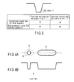
- FIG. 6 is a cross-sectional view showing mark shapes of an optical disk according to one embodiment of this invention.
- a mark (pit) 53 (a circle or ellipse indicated by a solid line) recorded on the disk is set to be smaller than a conventional mark 50 (an ellipse indicated by doted lines).
- the mark 50 has length calculated based on a reference clock.
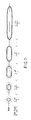
- FIG. 7 is a view showing marks (solid-line circle and ellipses) of 2T to 11T formed according to the present embodiment and ellipses indicated by dotted lines indicate conventional marks. Below the respective marks, the actual mark lengths for each T are shown. For example, L' 2T indicates the length (diameter) of the 2T mark (solid-line circle) in the track direction on the left end and the actual mark length for each T is (L'_2T)/2.
- the wall angles of the marks are so set that the front-side and back-side wall angles will be set to 43° and the right-side and left-side wall angles will be set to 48° as shown in FIG. 5 .
- a mark is recorded while the actual mark length of the mark is set smaller than in the conventional case (the mark length for each T is set smaller) as the mark length calculated based on the reference clock is smaller.
- the theoretical mark length of an nT mark calculated based on the reference clock T is set to L nT
- the actual length thereof is set to L' nT
- n that satisfies the expression of L nT ⁇ (playback beam spot diameter of playback drive) is set to n 1
- n that satisfies the expression of L nT > (playback beam spot diameter of playback drive) is set to n 2 .
- a disk according to the present embodiment satisfies the following expression.
- L ⁇ n ⁇ 1 ⁇ T / n 1 ⁇ L nT / n indicates the theoretical mark length for each T. More preferably, the following expression is set.
- the actual dimension of the pit is set smaller than the theoretical value.
- the actual mark length L' n0T is set smaller than 0.6 times the mark length theoretical value L n0T . That is, the actual dimensions of all of the marks are set equal to or smaller than the theoretical mark length and the actual dimension of a mark having a sizesmaller than at least the playback spot diameter is set extremely smaller than the theoretical mark length.
- the asymmetry of a playback signal is set to a smaller value and a disk manufactured by use of the next-generation master disk recording apparatus can be played back by use of a present HD DVD playback apparatus (player) without causing any problem.
- the minimum value of the magnification of the actual shortest mark length is x0.3 (approximately 61 nm). That is, even when the actual shortest mark length is set to 0.3 times the theoretical value, the amplitude of the playback signal thereof can be sufficiently large so as to be read by use of the present HD DVD playback apparatus.
- the disk according to the present embodiment is manufactured based on a master disk manufactured by use of a master disk recording apparatus (exposure apparatus) having a sufficiently high resolution to record the shortest marks.
- the recording beam diameter used for master disk recording is approximately 0.9 times the shortest pit length theoretical value and the tilts of the walls of the pit can be made steep (the cross section of the pit is rectangular). Therefore, a disk with high density can be easily manufactured by using a recording beam whose beam diameter is equal to or smaller than 0.9 times the shortest pit length theoretical value.
- the recording operation can be performed by use of a next-generation master disk recording apparatus of an electron beam recording system. As the result that the cross section of the pit is rectangular and the resolution becomes sufficiently high, the depths of recorded pits are uniformly set, and therefore, the quality of a playback signal becomes stable.
- a disk with high recording density in comparison with the present HD DVD (recording capacity: 15 GB/layer) can be easily manufactured.
- the shortest mark length calculated based on the reference clock is set to 0.204 ⁇ m, but the theoretical shortest mark length is set to 0.17 ⁇ m when the recording capacity is increased to 18 GB/layer.
- the range of the theoretical shortest mark length L n0T is substantially set to 0.17 ⁇ m to 0.21 ⁇ m.
- optical disk manufacturing method is explained below with reference to FIG. 8 .
- the flows of the optical disk manufacturing method using the conventional recording apparatus, the optical disk manufacturing method using the next-generation recording apparatus and the optical disk manufacturing method of this invention are basically the same. The different portions will be explained in detail.
- a glass plate (an Si wafer in the case of electron beam recording) 41 whose surface is polished and cleaned is used as a master disk (step 101).
- Photoresist 42 is coated on the surface of the master disk (an organic material is spin-coated or an inorganic material is sputtered in the case of thermal recording) (step 102) and then information is recorded by exposing the surface by use of laser light or an electron beam 46 (step 103). Then, the exposed master disk is developed to form irregular portions of pits (step 104).
- a stumper 43 with the thickness of approximately 300 ⁇ m is formed (step 105).
- the present invention contains a disk formation mold (stumper) having pits set to the above-described mark lengths.
- a resin (generally, polycarbonate) formation plate 44 is formed by injection molding with the stumper 43 used as a mold (step 106). After this, a reflection film and recording film are formed on the formation plate 44 (step 107), two formation plates are laminated (or a cover layer is formed on the formation plate) (step 108) and an optical disk is completed.
- the master disk of the optical disk to which this invention is applied is formed by use of a next-generation high-density master disk recording apparatus (for example, thermal recording by a laser or electron beam recording in the case of an HD DVD master disk) in the master disk recording step of the step 103.
- the next-generation high-density master disk recording apparatus has a sufficiently high exposure resolution for the present HD DVD or BD and a reflection level (signal amplitude) of the shortest mark which compares favorably with that of a mark with the other mark length can be attained.
- the theoretical shortest mark length is 0.204 ⁇ m, but the beam spot diameter can be narrowed to approximately 70 nm in the case of the electron beam recording apparatus (in contrast, a large spot diameter of several hundred nm as in the present master disk recording apparatus cannot be attained with the same apparatus configuration).
- the beam spot diameter is thus narrowed, the exposure line speed and exposure time that do not give any influence on production can be realized.
- the resolution is sufficiently high, the tilts of the pit walls by electron beam exposure become steeper than those by the conventional beam exposure and the pit shapes shown in FIG. 3 can be attained.
- the asymmetry is improved by setting the actual dimension of the mark (particularly, the shortest mark) that is smaller than the beam spot of the playback drive smaller than the conventional case.
- an ideal signal waveform can be attained when, particularly, the playback operation is performed by the PRML system.
- marks indicating information are formed of pit-form irregular portions and the actual shortest mark length is set according to the tilt angles (wall angles) of the pit wall surfaces. It is preferable to set the actual shortest mark length smaller as the wall angles are set larger (steeper) in comparison with the conventional case.
- An optical disk that satisfies the requirement of the present invention is actually manufactured.
- a surface AFM (Atomic Force Microscope) image of the optical disk is shown in FIG. 9 .
- the disk is an HD DVD-ROM disk whose recording density is 15 GB for each layer of the disk and the theoretical mark length of the shortest mark calculated based on the reference clock is 0.204 ⁇ m.
- the beam spot diameter of the master disk recording apparatus is 80 nm, the above problem first occurs and then the actual dimension of the mark length of the shortest mark is changed to solve the problem.
- the actual dimension of the shortest mark length was set to 0.90 ⁇ m (0.44 times the theoretical mark length), and as a result, the asymmetry was set small (the central levels of the signal amplitudes of the respective mark lengths were uniformly set at the center) and a signal waveform that is ideal for the PRML playback system could be attained.
- the beam spot of the drive used for playback was 0.550 ⁇ m (wavelength: 405 nm, NA: 0.65).
- a present optical disk such as an HD DVD or BD (whose density is relatively lower in comparison with the resolution of the next-generation master disk recording apparatus) can be manufactured by use of the next-generation master disk recording apparatus.
- the effect becomes particularly significant in an optical disk that plays back information by use of the PRML method.
- a playback signal waveform that is optimized for a signal process such as a PRML process can be attained, and at the same time, an old-generation low-density optical master disk can be recorded by use of the next-generation master disk recording apparatus in which the beam spot is narrowed for a next-generation high-density optical disk, and therefore, the operability of the apparatus can be enhanced.
- FIG. 10 is a block diagram showing the configuration of an optical disk device according to the present embodiment.
- An optical disk 61 is a read-only optical disk or an optical disk capable of recording user data.
- the optical disk 61 is rotated and driven by a spindle motor 63.
- the operation of recording or playing back information with respect to the optical disk 61 is performed by an optical pickup head (which is hereinafter referred to as a PUH) 65.
- the PUH 65 is connected with a thread motor 66 via a gear and the thread motor 66 is controlled by a thread motor control circuit 68.
- a seek destination address of the PUH 65 is input from a CPU 90 to the thread motor control circuit 68 and the thread motor control circuit 68 controls the thread motor 66 based on the address.
- a permanent magnet is fixed in the thread motor 66 and a drive coil 67 is excited by the thread motor control circuit 68 to move the PUH 65 in a radial direction of the optical disk 61.
- An objective lens 70 supported by a wire or leaf spring (not shown) is provided in the PUH 65.
- the objective lens 70 can be moved in a focusing direction (in the optical axis direction of the lens) by the driving operation of a drive coil 72 and can be moved in a tracking direction (in a direction perpendicular to the optical axis of the lens) by the driving operation of a drive coil 71.
- Recording data is input to a laser drive circuit 75 via a modulation circuit 74 in a laser control circuit 73 and the laser drive circuit 75 drives a semiconductor laser 79 to emit laser light based on input data.
- Laser light emitted from the semiconductor laser 75 is applied onto the optical disk 61 via a collimator lens 80, half prism 81 and objective lens 70.
- Light reflected from the optical disk 61 is guided to a photodetector 84 via the objective lens 70, half prism 81, condenser lens 82 and cylindrical lens 83.
- the photodetector 84 is configured by four-divided photodetector cells and detection signals from the divided photodetector cells are output to an RF amplifier 85.
- the RF amplifier 85 synthesizes the signals from the photodetector cells and generates a focus error signal FE indicating an error with respect to a just focused position, a tracking error signal TE indicating an error between the beam spot center of laser light and the track center and an RF signal that is a total sum signal of the signals from the photodetector cells.
- the focus error signal FE is supplied to a focusing control circuit 87.
- the focusing control circuit 87 generates a focus control signal FC according to the focus error signal FE.
- the focus control signal FC is supplied to the drive coil 72 for driving in the focusing direction and a focus servo operation is performed to always set laser light on a recording film of the optical disk 61 in a just focused state.
- the tracking error signal TE is supplied to a tracking control circuit 88.
- the tracking control circuit 88 generates a tracking control signal TC according to the tracking error signal TE.
- the tracking control signal TC is supplied to the drive coil 72 for driving in the tracking direction and a tracking servo operation is performed to always trace laser light on a track formed on the optical disk 61.
- a variation in the reflected light from a pit formed on the track of the optical disk 61 is reflected on the total sum signal RF of output signals of the photodetector cells of the photodetector 84.
- the signal is supplied to a data playback circuit 78.
- the data playback circuit 78 plays back recording data based on a playback clock signal from a PLL circuit 76.
- the thread motor 66 or PUH 65 is controlled by the thread motor control circuit 68 to set the objective lens 70 into a position near a preset position in the PUH 65.
- the motor control circuit 64, thread motor control circuit 68, laser control circuit 73, PLL circuit 76, data playback circuit 78, focusing control circuit 87, tracking control circuit 88, error correction circuit 62 and the like are controlled by the CPU 90 via a bus 89.
- the CPU 90 generally controls the recording/playback apparatus according to an operation command supplied from a host device 94 via an interface circuit 93. Further, the CPU 90 uses a RAM 91 as a work area and performs a preset operation according to a program recorded in a ROM 92.
- the data playback circuit 78 plays back information based on a binary-coding method in which the information playback signal waveform is sliced by use of threshold voltage and the sliced waveform is binary-coded or a PRML method in which the amplitude of the information playback signal waveform is converted into a multi-value and decoded.
- the diameter of a playback beam spot obtained by the objective lens 70 is preferably set to two to three times the theoretical shortest pit length. As described before, since the range of the theoretical shortest mark length L n0T is set to 0.17 ⁇ m to 0.21 ⁇ m in the optical disk according to the present embodiment, the optical disk playback apparatus plays back the optical disk by use of a laser light spot with the diameter of at least 0.34 ⁇ m to 0.63 ⁇ m.
- the optical disk playback apparatus calculates a correct reference clock and plays back a signal based on the playback waveform of the optical disk of this application having marks shorter than the theoretical mark length calculated based on the reference clock. For example, when the mark length of the actual shortest mark n 0 T is set to L' n0T , the optical disk playback apparatus plays back a signal based on a reference clock generated by setting the length (n 0 : an integral number and "2" in the case of an HD DVD) larger than or equal to (L' n0T /n 0 )/0.6 as the length corresponding to one period.
- the length corresponding to one period is a distance by which the light beam spot traces (moves along) the disk recording surface during one clock period.
Landscapes
- Engineering & Computer Science (AREA)
- Manufacturing & Machinery (AREA)
- Optical Recording Or Reproduction (AREA)
- Optical Record Carriers And Manufacture Thereof (AREA)
- Signal Processing For Digital Recording And Reproducing (AREA)
Applications Claiming Priority (1)
| Application Number | Priority Date | Filing Date | Title |
|---|---|---|---|
| JP2007145269A JP2008299955A (ja) | 2007-05-31 | 2007-05-31 | 光ディスク、光ディスク原盤作製方法及び光ディスク再生装置 |
Publications (1)
| Publication Number | Publication Date |
|---|---|
| EP1998326A1 true EP1998326A1 (de) | 2008-12-03 |
Family
ID=39590145
Family Applications (1)
| Application Number | Title | Priority Date | Filing Date |
|---|---|---|---|
| EP08156107A Withdrawn EP1998326A1 (de) | 2007-05-31 | 2008-05-13 | Optische Platte, Masterherstellungsverfahren für eine optische Platte und Wiedergabevorrichtung für eine optisches Platte |
Country Status (4)
| Country | Link |
|---|---|
| US (1) | US20080298220A1 (de) |
| EP (1) | EP1998326A1 (de) |
| JP (1) | JP2008299955A (de) |
| CN (1) | CN101315780A (de) |
Citations (4)
| Publication number | Priority date | Publication date | Assignee | Title |
|---|---|---|---|---|
| JP2000011453A (ja) * | 1998-06-29 | 2000-01-14 | Sony Corp | 光記録媒体と光記録再生装置 |
| EP1028413A2 (de) * | 1999-02-09 | 2000-08-16 | Sony Corporation | Optisches Aufzeichnungsmedium, Matrize zur Herstellung des optischen Aufzeichnungsmediums, und Verfahren zur Herstellung der Matrize |
| EP1215665A2 (de) * | 2000-12-15 | 2002-06-19 | Pioneer Corporation | Optische Platte mit Pits eines gewünschten Wandwinkels |
| US20040071074A1 (en) * | 2002-10-07 | 2004-04-15 | Kabushiki Kaisha Toshiba | Optical disk and optical disk apparatus |
-
2007
- 2007-05-31 JP JP2007145269A patent/JP2008299955A/ja active Pending
-
2008
- 2008-05-13 EP EP08156107A patent/EP1998326A1/de not_active Withdrawn
- 2008-05-30 CN CNA2008101086714A patent/CN101315780A/zh active Pending
- 2008-05-30 US US12/130,952 patent/US20080298220A1/en not_active Abandoned
Patent Citations (4)
| Publication number | Priority date | Publication date | Assignee | Title |
|---|---|---|---|---|
| JP2000011453A (ja) * | 1998-06-29 | 2000-01-14 | Sony Corp | 光記録媒体と光記録再生装置 |
| EP1028413A2 (de) * | 1999-02-09 | 2000-08-16 | Sony Corporation | Optisches Aufzeichnungsmedium, Matrize zur Herstellung des optischen Aufzeichnungsmediums, und Verfahren zur Herstellung der Matrize |
| EP1215665A2 (de) * | 2000-12-15 | 2002-06-19 | Pioneer Corporation | Optische Platte mit Pits eines gewünschten Wandwinkels |
| US20040071074A1 (en) * | 2002-10-07 | 2004-04-15 | Kabushiki Kaisha Toshiba | Optical disk and optical disk apparatus |
Also Published As
| Publication number | Publication date |
|---|---|
| CN101315780A (zh) | 2008-12-03 |
| JP2008299955A (ja) | 2008-12-11 |
| US20080298220A1 (en) | 2008-12-04 |
Similar Documents
| Publication | Publication Date | Title |
|---|---|---|
| CN100514453C (zh) | 用于光学记录介质的记录装置和记录方法 | |
| JP4335304B2 (ja) | 光学的情報記録方法、光学的情報記録媒体、および再生方法 | |
| US20090016206A1 (en) | Optical disk and optical disk apparatus | |
| JP4778940B2 (ja) | 光情報再生方法及び光情報再生装置 | |
| US7408860B2 (en) | Method of recording information in optical recording medium, information recording apparatus and optical recording medium | |
| CN101689384B (zh) | 光信息记录介质、光信息记录介质重放装置的控制方法 | |
| JP2009289386A (ja) | ガラスディスク、ガラスディスクのデータ再生方法、および、ガラスディスクの製造方法 | |
| US6934243B2 (en) | Optical information recording medium, recording/reproducing apparatus and recording /reproducing method for the same, and method for manufacturing optical information recording medium | |
| JP4705530B2 (ja) | 光記録媒体とその基板、及び該基板の成形用スタンパ | |
| KR20060043506A (ko) | 광 기록 매체, 광 기록 매체의 제조 방법, 기록/재생 방법및 기록/재생 장치 | |
| US20080298220A1 (en) | Optical disk, optical disk mastering method and optical disk playback apparatus | |
| JP4154256B2 (ja) | 光学式情報記録媒体の記録再生装置、および光学式情報記録媒体の記録再生方法 | |
| TWI242201B (en) | Optical recording medium | |
| JP2004296050A (ja) | 光ディスクならびに光ディスク装置 | |
| EP1806744A1 (de) | Aufzeichnungs-/wiedergabeverfahren für optisches aufzeichnungsmedium, optisches aufzeichnungsmedium und aufzeichnungs-/wiedergabevorrichtung dafür | |
| EP2458591A1 (de) | Verfahren zur Positionierung eines Fokusstrahlpunkts mit einer mehrschichtigen optischen Platte | |
| JP2006509320A (ja) | 長円形のスポットプロフィールを使用して追記型の光記録担体に情報を記録するための装置及び方法 | |
| TWI401678B (zh) | 光學資料儲存媒體及用以掃描此媒體之裝置及方法 | |
| KR20100080879A (ko) | 광학적 정보 기록 매체의 검사 방법, 검사 장치, 광학적 정보 기록 매체 및 정보 기록 방법 | |
| JP5496226B2 (ja) | 光学ドライブ装置 | |
| US7911929B2 (en) | Optical disk read only memory | |
| JP5394408B2 (ja) | 光学的情報再生装置、光学的情報再生方法及び集積回路 | |
| JP4431827B2 (ja) | 情報記録方法及び記録パワー決定方法 | |
| US20080159117A1 (en) | Optical disc, optical disc reproducing apparatus and optical disc reproducing method | |
| JP2009037698A (ja) | 光学情報記録媒体及び光学情報再生方法 |
Legal Events
| Date | Code | Title | Description |
|---|---|---|---|
| PUAI | Public reference made under article 153(3) epc to a published international application that has entered the european phase |
Free format text: ORIGINAL CODE: 0009012 |
|
| 17P | Request for examination filed |
Effective date: 20080513 |
|
| AK | Designated contracting states |
Kind code of ref document: A1 Designated state(s): AT BE BG CH CY CZ DE DK EE ES FI FR GB GR HR HU IE IS IT LI LT LU LV MC MT NL NO PL PT RO SE SI SK TR |
|
| AX | Request for extension of the european patent |
Extension state: AL BA MK RS |
|
| 17Q | First examination report despatched |
Effective date: 20090309 |
|
| AKX | Designation fees paid |
Designated state(s): DE FR GB |
|
| STAA | Information on the status of an ep patent application or granted ep patent |
Free format text: STATUS: THE APPLICATION IS DEEMED TO BE WITHDRAWN |
|
| 18D | Application deemed to be withdrawn |
Effective date: 20090721 |