EP1998138B1 - Verfahren und Vorrichtung für einen instrumentierten Befestiger - Google Patents
Verfahren und Vorrichtung für einen instrumentierten Befestiger Download PDFInfo
- Publication number
- EP1998138B1 EP1998138B1 EP08156872A EP08156872A EP1998138B1 EP 1998138 B1 EP1998138 B1 EP 1998138B1 EP 08156872 A EP08156872 A EP 08156872A EP 08156872 A EP08156872 A EP 08156872A EP 1998138 B1 EP1998138 B1 EP 1998138B1
- Authority
- EP
- European Patent Office
- Prior art keywords
- fastener
- instrumented
- assembly system
- light
- light beacon
- Prior art date
- Legal status (The legal status is an assumption and is not a legal conclusion. Google has not performed a legal analysis and makes no representation as to the accuracy of the status listed.)
- Active
Links
Images

Classifications
-
- G—PHYSICS
- G05—CONTROLLING; REGULATING
- G05B—CONTROL OR REGULATING SYSTEMS IN GENERAL; FUNCTIONAL ELEMENTS OF SUCH SYSTEMS; MONITORING OR TESTING ARRANGEMENTS FOR SUCH SYSTEMS OR ELEMENTS
- G05B19/00—Program-control systems
- G05B19/02—Program-control systems electric
- G05B19/18—Numerical control [NC], i.e. automatically operating machines, in particular machine tools, e.g. in a manufacturing environment, so as to execute positioning, movement or co-ordinated operations by means of program data in numerical form
- G05B19/401—Numerical control [NC], i.e. automatically operating machines, in particular machine tools, e.g. in a manufacturing environment, so as to execute positioning, movement or co-ordinated operations by means of program data in numerical form characterised by control arrangements for measuring, e.g. calibration and initialisation, measuring workpiece for machining purposes
-
- B—PERFORMING OPERATIONS; TRANSPORTING
- B21—MECHANICAL METAL-WORKING WITHOUT ESSENTIALLY REMOVING MATERIAL; PUNCHING METAL
- B21J—FORGING; HAMMERING; PRESSING METAL; RIVETING; FORGE FURNACES
- B21J15/00—Riveting
- B21J15/10—Riveting machines
- B21J15/14—Riveting machines specially adapted for riveting specific articles, e.g. brake lining machines
- B21J15/142—Aerospace structures
-
- G—PHYSICS
- G01—MEASURING; TESTING
- G01B—MEASURING LENGTH, THICKNESS OR SIMILAR LINEAR DIMENSIONS; MEASURING ANGLES; MEASURING AREAS; MEASURING IRREGULARITIES OF SURFACES OR CONTOURS
- G01B11/00—Measuring arrangements characterised by the use of optical techniques
- G01B11/26—Measuring arrangements characterised by the use of optical techniques for measuring angles or tapers; for testing the alignment of axes
- G01B11/27—Measuring arrangements characterised by the use of optical techniques for measuring angles or tapers; for testing the alignment of axes for testing the alignment of axes
- G01B11/272—Measuring arrangements characterised by the use of optical techniques for measuring angles or tapers; for testing the alignment of axes for testing the alignment of axes using photoelectric detection means
-
- G—PHYSICS
- G05—CONTROLLING; REGULATING
- G05B—CONTROL OR REGULATING SYSTEMS IN GENERAL; FUNCTIONAL ELEMENTS OF SUCH SYSTEMS; MONITORING OR TESTING ARRANGEMENTS FOR SUCH SYSTEMS OR ELEMENTS
- G05B19/00—Program-control systems
- G05B19/02—Program-control systems electric
- G05B19/418—Total factory control, i.e. centrally controlling a plurality of machines, e.g. direct or distributed numerical control [DNC], flexible manufacturing systems [FMS], integrated manufacturing systems [IMS] or computer integrated manufacturing [CIM]
- G05B19/41805—Total factory control, i.e. centrally controlling a plurality of machines, e.g. direct or distributed numerical control [DNC], flexible manufacturing systems [FMS], integrated manufacturing systems [IMS] or computer integrated manufacturing [CIM] characterised by assembly
-
- G—PHYSICS
- G05—CONTROLLING; REGULATING
- G05B—CONTROL OR REGULATING SYSTEMS IN GENERAL; FUNCTIONAL ELEMENTS OF SUCH SYSTEMS; MONITORING OR TESTING ARRANGEMENTS FOR SUCH SYSTEMS OR ELEMENTS
- G05B2219/00—Program-control systems
- G05B2219/30—Nc systems
- G05B2219/31—From computer integrated manufacturing till monitoring
- G05B2219/31047—Display image of finished workpiece on screen, show how, where to mount next part
-
- G—PHYSICS
- G05—CONTROLLING; REGULATING
- G05B—CONTROL OR REGULATING SYSTEMS IN GENERAL; FUNCTIONAL ELEMENTS OF SUCH SYSTEMS; MONITORING OR TESTING ARRANGEMENTS FOR SUCH SYSTEMS OR ELEMENTS
- G05B2219/00—Program-control systems
- G05B2219/30—Nc systems
- G05B2219/50—Machine tool, machine tool null till machine tool work handling
- G05B2219/50125—Configurable fixture, jig
-
- G—PHYSICS
- G05—CONTROLLING; REGULATING
- G05B—CONTROL OR REGULATING SYSTEMS IN GENERAL; FUNCTIONAL ELEMENTS OF SUCH SYSTEMS; MONITORING OR TESTING ARRANGEMENTS FOR SUCH SYSTEMS OR ELEMENTS
- G05B2219/00—Program-control systems
- G05B2219/30—Nc systems
- G05B2219/50—Machine tool, machine tool null till machine tool work handling
- G05B2219/50127—Modular fixture, use of clamps and locators, the latter also for positioning
-
- Y—GENERAL TAGGING OF NEW TECHNOLOGICAL DEVELOPMENTS; GENERAL TAGGING OF CROSS-SECTIONAL TECHNOLOGIES SPANNING OVER SEVERAL SECTIONS OF THE IPC; TECHNICAL SUBJECTS COVERED BY FORMER USPC CROSS-REFERENCE ART COLLECTIONS [XRACs] AND DIGESTS
- Y02—TECHNOLOGIES OR APPLICATIONS FOR MITIGATION OR ADAPTATION AGAINST CLIMATE CHANGE
- Y02P—CLIMATE CHANGE MITIGATION TECHNOLOGIES IN THE PRODUCTION OR PROCESSING OF GOODS
- Y02P90/00—Enabling technologies with a potential contribution to greenhouse gas [GHG] emissions mitigation
- Y02P90/02—Total factory control, e.g. smart factories, flexible manufacturing systems [FMS] or integrated manufacturing systems [IMS]
-
- Y—GENERAL TAGGING OF NEW TECHNOLOGICAL DEVELOPMENTS; GENERAL TAGGING OF CROSS-SECTIONAL TECHNOLOGIES SPANNING OVER SEVERAL SECTIONS OF THE IPC; TECHNICAL SUBJECTS COVERED BY FORMER USPC CROSS-REFERENCE ART COLLECTIONS [XRACs] AND DIGESTS
- Y10—TECHNICAL SUBJECTS COVERED BY FORMER USPC
- Y10T—TECHNICAL SUBJECTS COVERED BY FORMER US CLASSIFICATION
- Y10T29/00—Metal working
- Y10T29/49—Method of mechanical manufacture
- Y10T29/49616—Structural member making
- Y10T29/49622—Vehicular structural member making
-
- Y—GENERAL TAGGING OF NEW TECHNOLOGICAL DEVELOPMENTS; GENERAL TAGGING OF CROSS-SECTIONAL TECHNOLOGIES SPANNING OVER SEVERAL SECTIONS OF THE IPC; TECHNICAL SUBJECTS COVERED BY FORMER USPC CROSS-REFERENCE ART COLLECTIONS [XRACs] AND DIGESTS
- Y10—TECHNICAL SUBJECTS COVERED BY FORMER USPC
- Y10T—TECHNICAL SUBJECTS COVERED BY FORMER US CLASSIFICATION
- Y10T29/00—Metal working
- Y10T29/49—Method of mechanical manufacture
- Y10T29/49764—Method of mechanical manufacture with testing or indicating
- Y10T29/49778—Method of mechanical manufacture with testing or indicating with aligning, guiding, or instruction
- Y10T29/4978—Assisting assembly or disassembly
-
- Y—GENERAL TAGGING OF NEW TECHNOLOGICAL DEVELOPMENTS; GENERAL TAGGING OF CROSS-SECTIONAL TECHNOLOGIES SPANNING OVER SEVERAL SECTIONS OF THE IPC; TECHNICAL SUBJECTS COVERED BY FORMER USPC CROSS-REFERENCE ART COLLECTIONS [XRACs] AND DIGESTS
- Y10—TECHNICAL SUBJECTS COVERED BY FORMER USPC
- Y10T—TECHNICAL SUBJECTS COVERED BY FORMER US CLASSIFICATION
- Y10T29/00—Metal working
- Y10T29/49—Method of mechanical manufacture
- Y10T29/49826—Assembling or joining
- Y10T29/49947—Assembling or joining by applying separate fastener
- Y10T29/49963—Threaded fastener
-
- Y—GENERAL TAGGING OF NEW TECHNOLOGICAL DEVELOPMENTS; GENERAL TAGGING OF CROSS-SECTIONAL TECHNOLOGIES SPANNING OVER SEVERAL SECTIONS OF THE IPC; TECHNICAL SUBJECTS COVERED BY FORMER USPC CROSS-REFERENCE ART COLLECTIONS [XRACs] AND DIGESTS
- Y10—TECHNICAL SUBJECTS COVERED BY FORMER USPC
- Y10T—TECHNICAL SUBJECTS COVERED BY FORMER US CLASSIFICATION
- Y10T29/00—Metal working
- Y10T29/49—Method of mechanical manufacture
- Y10T29/49998—Work holding
Definitions
- the embodiments described herein generally relate to assembly and testing of structures, and more particularly relate to methods and apparatus for providing information regarding location and orientation of an assembly system with respect to such structures using intelligent fasteners.
- Another common technique involves the use of a small magnet, which can be placed inside a hole of the internal structural component, along with a magnet centroid finder that is moved along the outer surface until the center (i.e., the magnet) is located. An "X" or other such indicia is then marked on the surface, which is then identified by a vision system camera on the external portion of the assembly unit.
- Such systems are somewhat imprecise and generally provide only two-dimensional guidance (e.g., x and y position). Furthermore, such passive tacks are not configured to identify the specific structural location in which they are placed.
- US2001/0024283 relates to a system for identifying the position of a three-dimensional machine in a fixed frame of reference in which bushings fitted to a surface are fitted with emitters that emit a predetermined code enabling the bushing to be identified, from which the co-ordinates of a point associated with the surface can be deduced.
- US2003/0038933 concerns a calibration system in which optical targets such as an optical source and a diffusing target are fixed to a calibration surface.
- an instrumented fastener e.g., a "tack" fastener
- includes one or more light sources e.g., light-emitting diodes
- a light beacon that encodes information regarding the instrumented fastener (e.g., part number)
- the light beacon may be activated automatically, or via an instruction received from an external system.
- a plurality of such fasteners may be affixed to one or more airframe parts and used to autonomously assemble the various structures.
- an exemplary assembly task involves the joining of one or more components of a structure 102.
- a "skin" 104 of the box-type structure is shown in dotted lines, and generally defines an interior region 105 and exterior region 103. It will be understood that the particular beams, holes, and other components shown in FIG. 1 are merely examples, and in no way limits the range of applicable embodiments.
- FIG. 1 Two portions of an assembly system are illustrated in FIG. 1 : an external portion 110, and an internal portion 120.
- these two systems may be referred to herein as “external assembly system” 110 and “internal assembly system” 120, respectively, even though in practice they may be independent systems or two parts of the same system.
- Each assembly system 110 will typically include various end-effectors, actuators, and/or tools configured to perform the task at hand, and will also typically be attached to a robotic device and associated computer system (not shown in FIG. 1 ).
- fasteners 130 A number of instrumented fasteners (or simply “fasteners”) 130 have been attached to structure 102 at various points. In the illustrated embodiment, five such fasteners (130A, 130B, 130C, 130D, and 130E) are shown. In order to illustrate operation of the various embodiments, it is assumed that these fasteners 130 are "tack" fasteners - i.e., fasteners that help stabilize structure 102 temporarily, and which are replaced with a second, likely stronger, more permanent type of fastener, and which help with installing such permanent type fasteners in adjacent holes. Alternatively, fasteners 130 may be permanent fasteners.
- FIG. 1 shows internal assembly system 120 located above fastener 130B, and external assembly system 110 located below fastener 130B.
- each fastener 130 is configured to produce one or more light beacons 132 that can be sensed by assembly systems 110 and 120.
- This light beacon in addition to providing a reference for alignment, may also include encoded information (encoded by controller 230) regarding the nature and/or location of the respective fastener 130.
- fasteners 130 when activated, produce antipodal light beacons projecting outward along their major axes.
- external assembly system 110 When moving into position, external assembly system 110 receives beacon 132 through a port or lens 112. At the same time, internal assembly system 120 receives the antipodal beacon 132 within a sensor along underside 122 of the structure (not shown). Assembly systems 120 may then iteratively move themselves into the correct position and alignment based on the location of the received light on the sensor (i.e., aligned with the z axis as defined in this figure). That is, known techniques may be used to align the sensor such that it is centered and exhibits normality with respect to beacon 132.
- assembly systems 110 and 120 may then complete the required task before moving on to the next position (e.g., the next fastener 130).
- the next position e.g., the next fastener 130
- the position of known fastener locations between neighboring fasteners 130 may be computed, followed by installation of permanent fasteners therein.
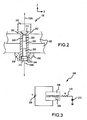
- fastener 130 includes a body 202 encasing a light source 210, another light source 212, one or more power sources 220, and a controller 230.
- Body 202 which has a major axis corresponding in this figure to the z-axis, may include a generally hollow, cylindrical cavity 240 large enough to fit the power source(s) 220 and controller 230.
- Body 202 may be threaded as shown to receive a corresponding nut 204, thus securing the components of structure 102.
- Body 202 may comprise any suitable material or combination of materials, including various plastics, ceramics, metals, and composites. Furthermore, body 202 may have any configuration and size, and is not limited to the tack fastener shown in FIG. 2 . In one embodiment, body 202 is generally cylindrical and has a diameter between approximately 0.15 - 0.50 inches (3.81-12.7mm).
- Light sources 210 and 212 are oriented such that, when activated by controller 230, and powered by power source 220, they produce opposing beacons 132A and 132B, respectively, which have maximum intensity in antipodal directions.
- External cavities 242 and 244 are shown adjacent to light sources 210 and 212, and function to protect light sources 210 and 212 from external impact and other forces.
- Light sources 210 and 212 may comprise any suitable light-emitting component, for example, a conventional light-emitting diode (LED). Furthermore, other parts of the electromagnetic spectrum other than visible light may be used.
- Power source 220 may include one or more batteries, such as various small conventional lithium-ion batteries known in the art.
- FIG. 3 shows a simplified block diagram of instrumented fastener 130.
- Controller 230 which receives a suitable voltage V from power source 220, selectively provides a current through resistor 310 to LED 210.
- Controller 230 may include any combination of hardware, software, and firmware configured to suitably control light sources 210 and 212.
- controller 230 may include a microprocessor, memory, I/O as is conventionally known.
- Controller 230 (or other components provided within body 202) may also be configured to receive external commands through, for example, a wireless communication protocol.
- Controller 230 may activate light sources 210 and 212 periodically, at predetermined times, or in response to an external instruction or stimulus. That is, assembly systems 110 and/or 120 (or the computer systems attached thereto) may be configured to wirelessly issue an instruction to controller 230 such that controller 230 activates the light sources only when the assembly systems are proximate to the fastener 130. Alternatively, controller 230 may sense the presence of the assembly system (e.g., via a conventional passive or active RFID scheme) and activate the light sources only when the assembly system is within a predetermined distance of fastener 130.
- beacons 132 it is desirable for beacons 132 to encode information relating to the nature and/or position of fastener 130.
- certain data 235 is preferably stored within controller 230 a priori. This data may include information regarding, for example, the part ID of fastener 130, its intended location within the structure (i.e., the particular airframe structure to which it is affixed), or any other such information.
- the data may be encoded and communicated in any desired manner.
- the data is stored as a digital word, and is communicated as a serial bit stream within beacon 132 by modulating the intensity of the beacon at a suitable clock rate. This modulation of intensity can then be read by sensors incorporated into the end-effectors of the assembly systems.
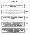
- a method of using an exemplary instrumented fastener to align an assembly system includes affixing an instrumented fastener to a structure (block 410), sending an instruction to the instrumented fastener to activate the instrumented fastener (block 420).
- the instrumented fastener produces a first light beacon along a first direction.
- the first light beacon may include information regarding the instrumented fastener.
- the instrumented fastener may also produce a second light beacon along a second direction antipodal to the first direction.
- the light beacon(s) are detected at the assembly system (block 430).
- the assembly system is aligned adjacent the instrumented fastener based on the direction of the light beacon(s) (block 440). For example, an external portion of the assembly system is aligned based on the first direction of the first light beacon, and an internal portion of the assembly system is aligned based on the second direction of the second light beacon.
- aligning the external portion of the assembly system includes alignment of an end-effector exhibiting four degrees of freedom.
- aligning the external portion of the assembly system includes determining a part number of the instrumented fastener based on the information included in the first light beacon.
- the method may further include utilizing the assembly system to replace the instrumented fastener with a permanent fastener (block 460).
Landscapes
- Engineering & Computer Science (AREA)
- Physics & Mathematics (AREA)
- General Physics & Mathematics (AREA)
- Automation & Control Theory (AREA)
- Manufacturing & Machinery (AREA)
- Mechanical Engineering (AREA)
- Human Computer Interaction (AREA)
- General Engineering & Computer Science (AREA)
- Quality & Reliability (AREA)
- Automatic Assembly (AREA)
- Toys (AREA)
- Fastening Of Light Sources Or Lamp Holders (AREA)
- Portable Nailing Machines And Staplers (AREA)
Claims (20)
- Mit Instrument versehenes Befestigungsmittel (130) mit:einem Befestigungsmittelkörper (202) mit einem ersten Ende und einem zweiten Ende;einer Stromquelle (220) in dem Befestigungsmittelkörper;einer Steuereinheit (230) in dem Befestigungsmittelkörper, wobei die Steuereinheit elektrisch mit der Stromquelle verbunden ist;einer ersten Lichtquelle (210), die an dem ersten Ende des Befestigungsmittelkörpers befestigt und kommunikativ mit der Steuereinheit verbunden ist, wobei die erste Lichtquelle konfiguriert ist, um einen ersten Lichtstrahl (132A) entlang einer ersten Richtung zu erzeugen, wenn sie aktiviert ist;wobei die Steuereinheit konfiguriert ist, um die erste Lichtquelle zu aktivieren, so dass der erste Lichtstrahl Informationen hinsichtlich des mit einem Instrument versehenen Befestigungsmittels enthält.
- Mit Instrument versehenes Befestigungsmittel (130) nach Anspruch 1, das des Weiteren eine zweite Lichtquelle (212) aufweist, die an dem zweiten Ende des Befestigungsmittels (202) befestigt und kommunikativ mit der Steuereinheit (230) verbunden ist, wobei die zweite Lichtquelle konfiguriert ist, um einen zweiten Lichtstrahl (132B) entlang einer zweiten Richtung zu erzeugen, wenn sie aktiviert ist.
- Mit Instrument versehenes Befestigungsmittel (130) nach Anspruch 2, wobei die erste Richtung und die zweite Richtung im Wesentlichen entgegengesetzt sind.
- Mit Instrument versehenes Befestigungsmittel (130) nach Anspruch 1, wobei der erste Lichtstrahl (132A) Informationen enthält, die einen seriellen Bitstrom mit einem oder mehreren digitalen Worten verwenden.
- Mit Instrument versehenes Befestigungsmittel (130) nach Anspruch 1, wobei der erste Lichtstrahl (132A) Informationen hinsichtlich einer Teile-Identifizierungsnummer des mit einem Instrument versehenen Befestigungsmittels enthält.
- Mit Instrument versehenes Befestigungsmittel (130) nach Anspruch 1, wobei die erste Lichtquelle (210) eine Leuchtdiode ist.
- Mit Instrument versehenes Befestigungsmittel (130) nach Anspruch 1, wobei das erste oder das zweite Ende des Befestigungsmittels (202) außen mit einem Gewinde versehen und konfiguriert ist, um eine entsprechende Gewindemutter (204) aufzunehmen.
- Mit Instrument versehenes Befestigungsmittel (130) nach Anspruch 1, wobei die Stromquelle (220) eine Batterie ist.
- Mit Instrument versehenes Befestigungsmittel (130) nach Anspruch 1, wobei der Befestigungsmittelkörper (202) einen Durchmesser zwischen ca. 3,81 und 12,7 mm hat.
- Mit Instrument versehenes Befestigungsmittel (130) nach Anspruch 1, wobei die Steuereinheit (230) konfiguriert ist, um die erste Lichtquelle (210) im Ansprechen auf einen externen Befehl zu aktivieren.
- Mit Instrument versehenes Befestigungsmittel (130) nach Anspruch 10, wobei der Regler (230) konfiguriert ist, um den externen Befehl von einem Montagesystem zu empfangen.
- Verfahren zum Ausrichten eines Montagesystems, wobei das Verfahren umfasst:Befestigen eines mit Instrument versehenen Befestigungsmittels (130) gemäß einem der vorhergehenden Ansprüche an einer Struktur (410), wobei das mit einem Instrument versehene Befestigungsmittel konfiguriert ist, um einen ersten Lichtstrahl (132A) entlang einer ersten Richtung zu erzeugen, wenn es aktiviert ist, wobei der erste Lichtstrahl Informationen hinsichtlich des mit einem Instrument versehenen Befestigungsmittels enthält;Ermitteln des ersten Lichtstrahls an einem Montagesystem; undAusrichten des Montagesystems neben dem mit einem Instrument versehenen Befestigungsmittel basierend auf der Richtung des ersten Lichtstrahls (440).
- Verfahren nach Anspruch 12, das des Weiteren, nach dem Schritt des Ausrichtens, das Verwenden des Montagesystems umfasst, um das mit einem Instrument versehene Befestigungsmittel (130) durch ein permanentes Befestigungsmittel (460) zu ersetzen.
- Verfahren nach Anspruch 12, wobei das mit einem Instrument versehene Befestigungsmittel (130) des Weiteren konfiguriert ist, um einen zweiten Lichtstrahl (132B) entlang einer zweiten, zur ersten Richtung entgegengesetzten Richtung zu erzeugen, und wobei der Schritt des Ausrichtens des Weiteren das Ausrichten eines äußeren Teils (110) des Montagesystems basierend auf der ersten Richtung des ersten Lichtstrahls (132A) und das Ausrichten eines inneren Teils (120) des Montagesystems basierend auf der zweiten Richtung des zweiten Lichtstrahls (132B) umfasst.
- Verfahren nach Anspruch 12, das des Weiteren umfasst:Senden eines Befehls (420) an das mit einem Instrument versehene Befestigungsmittel (130); undAktivieren des mit einem Instrument versehenen Befestigungsmittels im Ansprechen auf den Befehl.
- Verfahren zum Zusammenbauen eines Flugzeugs, wobei das Verfahren das Verfahren zum Ausrichten eines Montagesystems von Anspruch 12 umfasst,
wobei die Struktur eine Flugzeugzellenstruktur des Flugzeugs ist, wobei das mit einem Instrument versehene Befestigungsmittel konfiguriert ist, um, wenn es aktiviert ist, einen ersten Lichtstrahl (132A) entlang einer ersten Richtung und einen zweiten Lichtstrahl (132B) entlang einer zweiten, zur ersten Richtung entgegengesetzten Richtung zu erzeugen, wobei der erste und der zweite Lichtstrahl Informationen hinsichtlich des mit einem Instrument versehenen Befestigungsmittels enthalten;
wobei der Schritt des Ermittelns das Ermitteln (430) des ersten Lichtstrahls an einem äußeren Teil (110) eines Montagesystems und
das Ermitteln (430) des zweiten Lichtstrahls an einem inneren Teil (120) des Montagesystems umfasst;
und wobei der Schritt des Ausrichtens das Ausrichten (440) des äußeren Teils des Montagesystems neben dem mit einem Instrument versehenen Befestigungsmittel basierend auf der ersten Richtung des ersten Lichtstrahls und
das Ausrichten (440) des inneren Teils des Montagesystems neben dem mit einem Instrument versehenen Befestigungsmittel basierend auf der zweiten Richtung des zweiten Lichtstrahls umfasst. - Verfahren nach Anspruch 16, das des Weiteren, nach dem Schritt des Ausrichtens, das Verwenden (460) der äußeren (110) und inneren (120) Teile des Montagesystems umfasst, um das mit einem Instrument versehene Befestigungsmittel (130) durch ein permanentes Befestigungsmittel zu ersetzen.
- Verfahren nach Anspruch 16, das des Weiteren umfasst:Senden eines Befehls (420) an das mit einem Instrument versehene Befestigungsmittel (130); undAktivieren des mit einem Instrument versehenen Befestigungsmittels im Ansprechen auf den Befehl.
- Verfahren nach Anspruch 16, wobei das Ausrichten (440) des äußeren Abschnitts des Montagesystems (110) das Ausrichten eines Endeffektors mit vier Freiheitsgraden umfasst.
- Verfahren nach Anspruch 16, wobei das Ausrichten (440) des äußeren Teils des Montagesystems (110) das Ermitteln einer Teilenummer des mit einem Instrument versehenen Befestigungsmittels (130) basierend auf den in dem ersten Lichtstrahl enthaltenen Informationen umfasst.
Applications Claiming Priority (1)
| Application Number | Priority Date | Filing Date | Title |
|---|---|---|---|
| US11/756,447 US7937817B2 (en) | 2007-05-31 | 2007-05-31 | Methods and apparatus for an instrumented fastener |
Publications (2)
| Publication Number | Publication Date |
|---|---|
| EP1998138A1 EP1998138A1 (de) | 2008-12-03 |
| EP1998138B1 true EP1998138B1 (de) | 2012-03-07 |
Family
ID=39714193
Family Applications (1)
| Application Number | Title | Priority Date | Filing Date |
|---|---|---|---|
| EP08156872A Active EP1998138B1 (de) | 2007-05-31 | 2008-05-23 | Verfahren und Vorrichtung für einen instrumentierten Befestiger |
Country Status (6)
| Country | Link |
|---|---|
| US (1) | US7937817B2 (de) |
| EP (1) | EP1998138B1 (de) |
| JP (1) | JP5114296B2 (de) |
| CN (1) | CN101315273B (de) |
| AT (1) | ATE548631T1 (de) |
| ES (1) | ES2383839T3 (de) |
Families Citing this family (8)
| Publication number | Priority date | Publication date | Assignee | Title |
|---|---|---|---|---|
| US8301302B2 (en) | 2008-05-08 | 2012-10-30 | The Boeing Company | Synchronous robotic operation on a structure having a confined space |
| US20100217437A1 (en) * | 2009-02-24 | 2010-08-26 | Branko Sarh | Autonomous robotic assembly system |
| US8666546B2 (en) * | 2009-07-10 | 2014-03-04 | The Boeing Company | Autonomous robotic platform |
| US8544163B2 (en) | 2011-04-30 | 2013-10-01 | The Boeing Company | Robot having obstacle avoidance mechanism |
| US9764464B2 (en) | 2011-08-03 | 2017-09-19 | The Boeing Company | Robot including telescopic assemblies for positioning an end effector |
| US10386254B2 (en) * | 2016-04-25 | 2019-08-20 | The Boeing Company | Fastener Status Detection System |
| US10873357B2 (en) | 2017-05-02 | 2020-12-22 | Deere & Company | Smart attachment for a work vehicle |
| CN114440946B (zh) * | 2021-12-30 | 2024-05-24 | 重庆特斯联智慧科技股份有限公司 | 一种用于园区赋能平台智能学习的自编码装置 |
Family Cites Families (20)
| Publication number | Priority date | Publication date | Assignee | Title |
|---|---|---|---|---|
| US2206036A (en) * | 1938-07-27 | 1940-07-02 | Herson Jacob | Distance measuring apparatus and system |
| US4277170A (en) * | 1979-11-01 | 1981-07-07 | Miles Richard B | Laser beacon and optical detector system for aircraft collision hazard determination |
| US4934885A (en) | 1985-02-25 | 1990-06-19 | The Boeing Company | Tack fastener |
| KR950005415B1 (ko) * | 1986-09-19 | 1995-05-24 | 텍사스 인스트루먼츠 인코포레이티드 | 자동 로롯 장치 |
| US5202568A (en) * | 1991-09-03 | 1993-04-13 | Central Ohio Plastic Corporation | Determining the presence, position, and integrity of reinforcing mounting clips by utilizing photoelectric means |
| US5549803A (en) | 1994-01-14 | 1996-08-27 | Honeywell Inc. | Smart fastener |
| FR2721395B1 (fr) * | 1994-06-17 | 1996-08-14 | Homer Eaton | Procédé de repérage positionnel d'un trièdre dans l'espace et dispositif pour la mise en Óoeuvre de ce procédé. |
| US5577829A (en) | 1995-01-09 | 1996-11-26 | Hall; Timothy E. | Flashlight with tool bit attachment |
| US6056283A (en) | 1999-02-08 | 2000-05-02 | The Boeing Company | Tack fastener |
| US6196779B1 (en) | 1999-02-11 | 2001-03-06 | The Boeing Company | Temporary fastener with projecting tool-guide bushing |
| FR2806657B1 (fr) * | 2000-03-21 | 2002-08-16 | Romain Granger | Systeme de reperage positionnel d'une machine tridimensionnelle dans un referentiel fixe |
| US6643019B1 (en) * | 2000-04-13 | 2003-11-04 | Jack D. Jeanneret | Laser alignment device |
| WO2002086420A1 (en) * | 2001-04-19 | 2002-10-31 | Dimensional Photonics, Inc. | Calibration apparatus, system and method |
| US6741364B2 (en) * | 2002-08-13 | 2004-05-25 | Harris Corporation | Apparatus for determining relative positioning of objects and related methods |
| TWM242685U (en) * | 2003-03-04 | 2004-09-01 | Quarton Inc | Three-direction laser indicator |
| AU2003902259A0 (en) * | 2003-05-13 | 2003-05-29 | Telezygology Inc. | Improved assembly system |
| US7216436B2 (en) * | 2004-08-24 | 2007-05-15 | Bell Helicopter Textron Inc. | Method and apparatus for locating and aligning fasteners |
| US20070204473A1 (en) * | 2006-03-03 | 2007-09-06 | Honda Motor Co., Ltd. | Spindle locating laser for nut runner |
| US7557936B2 (en) * | 2006-04-12 | 2009-07-07 | Toyota Motor Engineering & Manufacturing North America, Inc. | Digitizer adapter |
| US20070262933A1 (en) * | 2006-05-11 | 2007-11-15 | Advanced Lighting Systems, Inc. A Minnesota Corporation | System and method for mounting LED's on a display surface |
-
2007
- 2007-05-31 US US11/756,447 patent/US7937817B2/en active Active
-
2008
- 2008-05-23 EP EP08156872A patent/EP1998138B1/de active Active
- 2008-05-23 AT AT08156872T patent/ATE548631T1/de active
- 2008-05-23 ES ES08156872T patent/ES2383839T3/es active Active
- 2008-06-02 JP JP2008144312A patent/JP5114296B2/ja active Active
- 2008-06-02 CN CN2008101087967A patent/CN101315273B/zh active Active
Also Published As
| Publication number | Publication date |
|---|---|
| CN101315273B (zh) | 2011-12-28 |
| JP2009078347A (ja) | 2009-04-16 |
| JP5114296B2 (ja) | 2013-01-09 |
| CN101315273A (zh) | 2008-12-03 |
| US7937817B2 (en) | 2011-05-10 |
| ES2383839T3 (es) | 2012-06-26 |
| US20080295314A1 (en) | 2008-12-04 |
| EP1998138A1 (de) | 2008-12-03 |
| HK1122612A1 (en) | 2009-05-22 |
| ATE548631T1 (de) | 2012-03-15 |
Similar Documents
| Publication | Publication Date | Title |
|---|---|---|
| EP1998138B1 (de) | Verfahren und Vorrichtung für einen instrumentierten Befestiger | |
| JP7496562B2 (ja) | 工具システム | |
| CN106477068A (zh) | 机器人系统和操作机器人系统的方法 | |
| KR100812724B1 (ko) | 실내 위치측정시스템을 이용한 벽면 이동 로봇 | |
| KR101644642B1 (ko) | 제한된 공간을 갖는 구조 상에서의 동기 로봇 조작 | |
| US20050102060A1 (en) | Device for correcting positional data of robot | |
| WO2018035482A1 (en) | Robotic drone | |
| WO2018213931A1 (en) | Systems and methods for process tending with a robot arm | |
| CN105786018B (zh) | 一种无人机用自动返航激光定位系统、无人机 | |
| KR20110115097A (ko) | 산업용 로봇의 아암의 기준 위치 결정 방법 및 산업용 로봇 | |
| EP1515210A3 (de) | Robotersystem und Steuerverfahren hierzu | |
| CN110509297B (zh) | 一种二维码检测机器人、检测系统及检测方法 | |
| HK1122612B (en) | Methods and apparatus for an instrumented fastener | |
| KR20230090851A (ko) | 드론 스테이션 및 드론 시스템 | |
| EP3263293B1 (de) | Analyse von endeffektoroperationen durch einen roboter | |
| EP3801231B1 (de) | Messvorrichtung zur messung physiologischer daten eines säugetiers | |
| CN210147390U (zh) | 一种圆柱磁石组装机构 | |
| Reed | PROJECT ADVISOR: James Rogers MAIN AUTHORS: Muhammad H. Abdelraziq | |
| CN120447538A (zh) | 一种自动搬运车导引系统及导引方法 | |
| Saravanakumar | Passive Battery Transport Using Tendon Soft Grippers in Drones | |
| KR101207173B1 (ko) | 공간 인지 학습을 통해 자력으로 목표 장소로 이동하는 이동체 시스템 | |
| KR20250077995A (ko) | 시설하우스용 로봇의 주행제어시스템 | |
| WO2025253971A1 (ja) | 搬送システム、搬送装置、アタッチメント、被把持部、把持部、部品実装システム、及び制御方法 | |
| Paromtchik | GUIDANCE SYSTEM FOR ROBOTS CAPABLE OF VISION AND COMMUNICATION | |
| Brown et al. | IEEE Robotics Competition Design |
Legal Events
| Date | Code | Title | Description |
|---|---|---|---|
| PUAI | Public reference made under article 153(3) epc to a published international application that has entered the european phase |
Free format text: ORIGINAL CODE: 0009012 |
|
| 17P | Request for examination filed |
Effective date: 20080527 |
|
| AK | Designated contracting states |
Kind code of ref document: A1 Designated state(s): AT BE BG CH CY CZ DE DK EE ES FI FR GB GR HR HU IE IS IT LI LT LU LV MC MT NL NO PL PT RO SE SI SK TR |
|
| AX | Request for extension of the european patent |
Extension state: AL BA MK RS |
|
| 17Q | First examination report despatched |
Effective date: 20090128 |
|
| AKX | Designation fees paid |
Designated state(s): AT BE BG CH CY CZ DE DK EE ES FI FR GB GR HR HU IE IS IT LI LT LU LV MC MT NL NO PL PT RO SE SI SK TR |
|
| GRAP | Despatch of communication of intention to grant a patent |
Free format text: ORIGINAL CODE: EPIDOSNIGR1 |
|
| RTI1 | Title (correction) |
Free format text: METHOD AND APPARATUS FOR AN INSTRUMENTED FASTENER |
|
| GRAS | Grant fee paid |
Free format text: ORIGINAL CODE: EPIDOSNIGR3 |
|
| GRAA | (expected) grant |
Free format text: ORIGINAL CODE: 0009210 |
|
| AK | Designated contracting states |
Kind code of ref document: B1 Designated state(s): AT BE BG CH CY CZ DE DK EE ES FI FR GB GR HR HU IE IS IT LI LT LU LV MC MT NL NO PL PT RO SE SI SK TR |
|
| REG | Reference to a national code |
Ref country code: GB Ref legal event code: FG4D |
|
| REG | Reference to a national code |
Ref country code: CH Ref legal event code: EP Ref country code: AT Ref legal event code: REF Ref document number: 548631 Country of ref document: AT Kind code of ref document: T Effective date: 20120315 |
|
| REG | Reference to a national code |
Ref country code: IE Ref legal event code: FG4D |
|
| REG | Reference to a national code |
Ref country code: DE Ref legal event code: R096 Ref document number: 602008013885 Country of ref document: DE Effective date: 20120503 |
|
| REG | Reference to a national code |
Ref country code: ES Ref legal event code: FG2A Ref document number: 2383839 Country of ref document: ES Kind code of ref document: T3 Effective date: 20120626 |
|
| REG | Reference to a national code |
Ref country code: NL Ref legal event code: VDEP Effective date: 20120307 |
|
| PG25 | Lapsed in a contracting state [announced via postgrant information from national office to epo] |
Ref country code: LT Free format text: LAPSE BECAUSE OF FAILURE TO SUBMIT A TRANSLATION OF THE DESCRIPTION OR TO PAY THE FEE WITHIN THE PRESCRIBED TIME-LIMIT Effective date: 20120307 Ref country code: NL Free format text: LAPSE BECAUSE OF FAILURE TO SUBMIT A TRANSLATION OF THE DESCRIPTION OR TO PAY THE FEE WITHIN THE PRESCRIBED TIME-LIMIT Effective date: 20120307 Ref country code: NO Free format text: LAPSE BECAUSE OF FAILURE TO SUBMIT A TRANSLATION OF THE DESCRIPTION OR TO PAY THE FEE WITHIN THE PRESCRIBED TIME-LIMIT Effective date: 20120607 Ref country code: HR Free format text: LAPSE BECAUSE OF FAILURE TO SUBMIT A TRANSLATION OF THE DESCRIPTION OR TO PAY THE FEE WITHIN THE PRESCRIBED TIME-LIMIT Effective date: 20120307 |
|
| LTIE | Lt: invalidation of european patent or patent extension |
Effective date: 20120307 |
|
| PG25 | Lapsed in a contracting state [announced via postgrant information from national office to epo] |
Ref country code: GR Free format text: LAPSE BECAUSE OF FAILURE TO SUBMIT A TRANSLATION OF THE DESCRIPTION OR TO PAY THE FEE WITHIN THE PRESCRIBED TIME-LIMIT Effective date: 20120608 Ref country code: FI Free format text: LAPSE BECAUSE OF FAILURE TO SUBMIT A TRANSLATION OF THE DESCRIPTION OR TO PAY THE FEE WITHIN THE PRESCRIBED TIME-LIMIT Effective date: 20120307 Ref country code: LV Free format text: LAPSE BECAUSE OF FAILURE TO SUBMIT A TRANSLATION OF THE DESCRIPTION OR TO PAY THE FEE WITHIN THE PRESCRIBED TIME-LIMIT Effective date: 20120307 |
|
| REG | Reference to a national code |
Ref country code: AT Ref legal event code: MK05 Ref document number: 548631 Country of ref document: AT Kind code of ref document: T Effective date: 20120307 |
|
| PG25 | Lapsed in a contracting state [announced via postgrant information from national office to epo] |
Ref country code: CY Free format text: LAPSE BECAUSE OF FAILURE TO SUBMIT A TRANSLATION OF THE DESCRIPTION OR TO PAY THE FEE WITHIN THE PRESCRIBED TIME-LIMIT Effective date: 20120307 |
|
| PG25 | Lapsed in a contracting state [announced via postgrant information from national office to epo] |
Ref country code: IS Free format text: LAPSE BECAUSE OF FAILURE TO SUBMIT A TRANSLATION OF THE DESCRIPTION OR TO PAY THE FEE WITHIN THE PRESCRIBED TIME-LIMIT Effective date: 20120707 Ref country code: EE Free format text: LAPSE BECAUSE OF FAILURE TO SUBMIT A TRANSLATION OF THE DESCRIPTION OR TO PAY THE FEE WITHIN THE PRESCRIBED TIME-LIMIT Effective date: 20120307 Ref country code: PL Free format text: LAPSE BECAUSE OF FAILURE TO SUBMIT A TRANSLATION OF THE DESCRIPTION OR TO PAY THE FEE WITHIN THE PRESCRIBED TIME-LIMIT Effective date: 20120307 Ref country code: CZ Free format text: LAPSE BECAUSE OF FAILURE TO SUBMIT A TRANSLATION OF THE DESCRIPTION OR TO PAY THE FEE WITHIN THE PRESCRIBED TIME-LIMIT Effective date: 20120307 Ref country code: SE Free format text: LAPSE BECAUSE OF FAILURE TO SUBMIT A TRANSLATION OF THE DESCRIPTION OR TO PAY THE FEE WITHIN THE PRESCRIBED TIME-LIMIT Effective date: 20120307 Ref country code: BE Free format text: LAPSE BECAUSE OF FAILURE TO SUBMIT A TRANSLATION OF THE DESCRIPTION OR TO PAY THE FEE WITHIN THE PRESCRIBED TIME-LIMIT Effective date: 20120307 Ref country code: SI Free format text: LAPSE BECAUSE OF FAILURE TO SUBMIT A TRANSLATION OF THE DESCRIPTION OR TO PAY THE FEE WITHIN THE PRESCRIBED TIME-LIMIT Effective date: 20120307 Ref country code: RO Free format text: LAPSE BECAUSE OF FAILURE TO SUBMIT A TRANSLATION OF THE DESCRIPTION OR TO PAY THE FEE WITHIN THE PRESCRIBED TIME-LIMIT Effective date: 20120307 |
|
| PG25 | Lapsed in a contracting state [announced via postgrant information from national office to epo] |
Ref country code: SK Free format text: LAPSE BECAUSE OF FAILURE TO SUBMIT A TRANSLATION OF THE DESCRIPTION OR TO PAY THE FEE WITHIN THE PRESCRIBED TIME-LIMIT Effective date: 20120307 Ref country code: PT Free format text: LAPSE BECAUSE OF FAILURE TO SUBMIT A TRANSLATION OF THE DESCRIPTION OR TO PAY THE FEE WITHIN THE PRESCRIBED TIME-LIMIT Effective date: 20120709 |
|
| PG25 | Lapsed in a contracting state [announced via postgrant information from national office to epo] |
Ref country code: MC Free format text: LAPSE BECAUSE OF NON-PAYMENT OF DUE FEES Effective date: 20120531 |
|
| REG | Reference to a national code |
Ref country code: CH Ref legal event code: PL |
|
| PLBE | No opposition filed within time limit |
Free format text: ORIGINAL CODE: 0009261 |
|
| STAA | Information on the status of an ep patent application or granted ep patent |
Free format text: STATUS: NO OPPOSITION FILED WITHIN TIME LIMIT |
|
| PG25 | Lapsed in a contracting state [announced via postgrant information from national office to epo] |
Ref country code: DK Free format text: LAPSE BECAUSE OF FAILURE TO SUBMIT A TRANSLATION OF THE DESCRIPTION OR TO PAY THE FEE WITHIN THE PRESCRIBED TIME-LIMIT Effective date: 20120307 Ref country code: AT Free format text: LAPSE BECAUSE OF FAILURE TO SUBMIT A TRANSLATION OF THE DESCRIPTION OR TO PAY THE FEE WITHIN THE PRESCRIBED TIME-LIMIT Effective date: 20120307 Ref country code: LI Free format text: LAPSE BECAUSE OF NON-PAYMENT OF DUE FEES Effective date: 20120531 Ref country code: CH Free format text: LAPSE BECAUSE OF NON-PAYMENT OF DUE FEES Effective date: 20120531 |
|
| 26N | No opposition filed |
Effective date: 20121210 |
|
| REG | Reference to a national code |
Ref country code: IE Ref legal event code: MM4A |
|
| REG | Reference to a national code |
Ref country code: DE Ref legal event code: R097 Ref document number: 602008013885 Country of ref document: DE Effective date: 20121210 |
|
| PG25 | Lapsed in a contracting state [announced via postgrant information from national office to epo] |
Ref country code: IE Free format text: LAPSE BECAUSE OF NON-PAYMENT OF DUE FEES Effective date: 20120523 |
|
| PG25 | Lapsed in a contracting state [announced via postgrant information from national office to epo] |
Ref country code: BG Free format text: LAPSE BECAUSE OF FAILURE TO SUBMIT A TRANSLATION OF THE DESCRIPTION OR TO PAY THE FEE WITHIN THE PRESCRIBED TIME-LIMIT Effective date: 20120607 Ref country code: MT Free format text: LAPSE BECAUSE OF FAILURE TO SUBMIT A TRANSLATION OF THE DESCRIPTION OR TO PAY THE FEE WITHIN THE PRESCRIBED TIME-LIMIT Effective date: 20120307 |
|
| PG25 | Lapsed in a contracting state [announced via postgrant information from national office to epo] |
Ref country code: TR Free format text: LAPSE BECAUSE OF FAILURE TO SUBMIT A TRANSLATION OF THE DESCRIPTION OR TO PAY THE FEE WITHIN THE PRESCRIBED TIME-LIMIT Effective date: 20120307 |
|
| PG25 | Lapsed in a contracting state [announced via postgrant information from national office to epo] |
Ref country code: LU Free format text: LAPSE BECAUSE OF NON-PAYMENT OF DUE FEES Effective date: 20120523 |
|
| PG25 | Lapsed in a contracting state [announced via postgrant information from national office to epo] |
Ref country code: HU Free format text: LAPSE BECAUSE OF FAILURE TO SUBMIT A TRANSLATION OF THE DESCRIPTION OR TO PAY THE FEE WITHIN THE PRESCRIBED TIME-LIMIT Effective date: 20080523 |
|
| REG | Reference to a national code |
Ref country code: FR Ref legal event code: PLFP Year of fee payment: 9 |
|
| REG | Reference to a national code |
Ref country code: FR Ref legal event code: PLFP Year of fee payment: 10 |
|
| REG | Reference to a national code |
Ref country code: FR Ref legal event code: PLFP Year of fee payment: 11 |
|
| P01 | Opt-out of the competence of the unified patent court (upc) registered |
Effective date: 20230516 |
|
| PGFP | Annual fee paid to national office [announced via postgrant information from national office to epo] |
Ref country code: DE Payment date: 20250529 Year of fee payment: 18 |
|
| PGFP | Annual fee paid to national office [announced via postgrant information from national office to epo] |
Ref country code: GB Payment date: 20250527 Year of fee payment: 18 Ref country code: ES Payment date: 20250602 Year of fee payment: 18 |
|
| PGFP | Annual fee paid to national office [announced via postgrant information from national office to epo] |
Ref country code: IT Payment date: 20250521 Year of fee payment: 18 |
|
| PGFP | Annual fee paid to national office [announced via postgrant information from national office to epo] |
Ref country code: FR Payment date: 20250526 Year of fee payment: 18 |