EP1998054A2 - Pneumatikzylinder mit einer selbsteinstellenden Endlagendämpfung und entsprechendes Verfahren - Google Patents
Pneumatikzylinder mit einer selbsteinstellenden Endlagendämpfung und entsprechendes Verfahren Download PDFInfo
- Publication number
- EP1998054A2 EP1998054A2 EP08156234A EP08156234A EP1998054A2 EP 1998054 A2 EP1998054 A2 EP 1998054A2 EP 08156234 A EP08156234 A EP 08156234A EP 08156234 A EP08156234 A EP 08156234A EP 1998054 A2 EP1998054 A2 EP 1998054A2
- Authority
- EP
- European Patent Office
- Prior art keywords
- damping
- cylinder
- pressure
- piston
- cylinder piston
- Prior art date
- Legal status (The legal status is an assumption and is not a legal conclusion. Google has not performed a legal analysis and makes no representation as to the accuracy of the status listed.)
- Granted
Links
Images


Classifications
-
- F—MECHANICAL ENGINEERING; LIGHTING; HEATING; WEAPONS; BLASTING
- F15—FLUID-PRESSURE ACTUATORS; HYDRAULICS OR PNEUMATICS IN GENERAL
- F15B—SYSTEMS ACTING BY MEANS OF FLUIDS IN GENERAL; FLUID-PRESSURE ACTUATORS, e.g. SERVOMOTORS; DETAILS OF FLUID-PRESSURE SYSTEMS, NOT OTHERWISE PROVIDED FOR
- F15B15/00—Fluid-actuated devices for displacing a member from one position to another; Gearing associated therewith
- F15B15/20—Other details, e.g. assembly with regulating devices
- F15B15/22—Other details, e.g. assembly with regulating devices for accelerating or decelerating the stroke
- F15B15/223—Other details, e.g. assembly with regulating devices for accelerating or decelerating the stroke having a piston with a piston extension or piston recess which completely seals the main fluid outlet as the piston approaches its end position
Definitions
- the subject invention relates to a pneumatic cylinder with a self-adjusting end position damping with a cylinder housing in which a movable cylinder piston is arranged, which is acted upon by pressure on one side and by the movement of the cylinder piston in the region of the end position of the cylinder piston from the non-pressurized side the cylinder piston limited damping volume is formed, and a method for self-adjusting end position damping.
- a cushioning is often used to prevent the piston strikes in the end position against the cylinder housing or against a stop.
- the aim of the end position damping is therefore to reduce the speed of a moving mass (piston + load), whose center of gravity is usually in the cylinder axis, to a level at which neither the cylinder nor the machine in which the cylinder is installed, damaged or impacted by initiated impacts.
- the volume can not be dissipated in the same time in which the piston retracts, which is why there is a pressure increase in this chamber.
- the piston is decelerated by this pressure and should therefore not hit the cylinder cover or an end stop, but slowly retract with the time-delayed escape of air.
- the valve needle is set during commissioning of the cylinder.
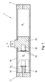
- This form of end position damping can be found in many pneumatic or hydraulic cylinders which have a cushioning, such as in a rodless pneumatic cylinder 1 as in Fig. 1 shown.
- the disadvantage of this cushioning is that only a certain kinetic energy can be reduced by the fixed setting of the valve needle.
- path-dependent Endlagendämpfonne are known, such as from the EP 949 422 A1 , which change an exhaust air cross-section as a function of the piston position and thus can specify a progressive damping curve.
- this Dämpfverlauf is dependent on the fixed geometry and can thus be optimal only for a certain combination of mass and speed. If the pneumatic cylinder is operated away from the optimum operating point, eg if the working pressure (and thus the speed) changes or if another load is moved, the damping is no longer optimal. But this is exactly the case in practice, as it has been shown that the positions where the pressure peaks occur are different depending on the load and speed.
- pneumatic shock absorbers are known, for example from the DE 37 40 669 A1 , with an outlet valve, over which the air compressed during a damping movement of the piston is discharged.
- a valve tappet is biased by the working pressure and a spring force.
- the exhaust valve opens abruptly and the compressed air is released via a throttle.
- the objective of the subject invention has set itself the task to provide a cushioning of a pneumatic cylinder, and an associated method, which automatically to different operating parameters, such as. Mass, speed and working pressure, adjusted to achieve a wide range optimal damping and which is simple and inexpensive designed.
- the end position damping comprises a displacement which is limited by a movable lifting element and a part of the pneumatic cylinder, wherein the displacement is connected via a connecting channel with the cylinder piston acting on the working pressure or applied in an outlet venting pressure and the Lifting element is acted upon by a damping channel from the pressure in the damping volume, in the connecting channel before the displacement of a check valve is arranged, which blocks in the direction of the working pressure and the venting pressure and that a venting channel is provided, which can be opened with the movable lifting element is and which is connected to an exhaust duct.
- the inventive method results from the fact that in the damping volume by the movement of the cylinder piston, a damping pressure is applied to a lifting element is acted upon, the lifting element is moved by the damping pressure against a completed in a displacement, acted upon by the working pressure or the venting pressure fluid volume and through the movement of the lifting element is opened a venting channel.
- the spring constant of this gas spring changes independently depending on the prevailing pressures and it is achieved a constant damping effect even at different operating pressures and different kinetic energies.
- the venting pressure is used in the adaptive gas spring, since the pressure profile on the vent side shows a more pronounced dependence on the travel speed of the cylinder piston and is thus better suited as a controlled variable.
- the invention thereby increases the comfort, reliability and ease of use of the pneumatic drive.
- the automatic adjustment of the end-of-stroke damping to the operating conditions also eliminates the costs for manual adjustment and reduces cycle times.
- the damping volume is advantageously formed by a in the axial direction in the cylinder housing extending damper pin is arranged in the region of the end stop of the cylinder piston and the cylinder piston is designed with a recess accommodating the damping pin. Characterized the cylinder volume is divided when retracting the damper pin in the recess for forming the damping volume.
- the damping volume may also be formed by arranging an exhaust duct laterally on the cylinder housing and axially spaced from the cylinder cover.
- the lifting element is designed as guided in the displacement mounted damping piston.
- the displacement or the damping piston can, depending on the structural design, either be arranged in a cylinder cover closing off the pneumatic cylinder or in the cylinder piston.
- the lifting element may also be a sealing element between the damping pin and the cylinder piston, wherein the sealing element is hollow and is arranged in the cylinder piston.
- a vent opening may be provided on the pneumatic cylinder which is connected to the damping volume.
- Fig. 2 is an end, here the completed by the cylinder cover 4 end of a pneumatic cylinder 1, here for example a rodless pneumatic cylinder, shown with a self-adjusting end position damping according to the invention in detail.
- the cylinder piston 22 is, for example via a carriage, connected to a mass m and moves under pressurization p 1 on one of its sides at a speed v in a cylinder housing 15 in the direction of the mechanical end stop (in the region of the cylinder cover 4).
- the cylinder piston 22 is sealed relative to the cylinder housing in a known manner by means of sealing elements 20.
- the direction of movement is in Fig. 2 indicated by the arrow.
- the displaced by the movement of air on the non-pressurized side of the cylinder piston 22 is discharged via a channel 3 in the cylinder cover 4 and a connection not shown here.
- a recess 23 is provided which can receive a axially extending into the cylinder housing 15 Dämpfzapfen 18.
- the damping pin 18 is arranged in this example on the cylinder cover 4 and in the end region or in the region of an end position of the cylinder piston 22 of the pneumatic cylinder 1, resulting in a Dämpf Scheme.
- An outlet channel 3 extends here in the axial direction through the cylinder cover 4 and through the damping pin 18.
- such a damping volume 19 can also be formed differently, in particular without damping pin 18, for example by the outlet channel 3 being laterally spaced apart from the cylinder cover 4 in the axial direction is arranged on the cylinder housing 15, as in Fig. 2 indicated by dashed lines and indicated by reference numeral 3a.
- the outlet channel 3a is closed during the movement of the cylinder piston 22, resulting in the end position of the cylinder piston 22 between the cylinder cover 4 and cylinder piston 22 again a corresponding damping volume 19.
- a displacement 9 is provided - here a simple bore, which is closed by a disc 10.
- the displacement 9 is limited by a lifting element, here a damper piston 7, the movable (as indicated by the double arrow in Fig. 2 indicated) and guided in the displacement 9 is arranged.
- the displacement 9 is connected here via a channel 11 in the cylinder cover 4 and a cylinder housing 15 arranged in the connecting channel 14 with the working pressure p 1 on the pressurized side of the cylinder piston 22.
- a check valve 12 is arranged that blocks in the direction of the working pressure p 1 .
- the damping piston 7 is therefore pressurized on one side by the force acting in the displacement 9 working pressure p 1 .
- the opposite side 6 of the damper piston 7 is executed stepped in this example and is connected via a damping channel 16 with the damping volume 19.
- the damper piston 7 closes a venting channel 5 arranged in the cylinder cover 4 and connected to the outlet duct 3.
- the damper piston 7 may be provided for sealing against the cylinder cover 4 with throttling grooves 8. Instead of throttling grooves 8 but also any other sealing elements may be provided.
- a targeted leakage can be provided via the throttling grooves 8 or the other sealing elements at this point for pressure reduction in the displacement 9.
- vent the displacement 9 between two strokes if necessary via other suitable means, such as a valve or throttle, or to pressurize it with the new working pressure p 1 .
- end position damping can also be provided on the other side of the pneumatic cylinder, so that the opposite movement is endlagengedämpft accordingly.
- the same arrangement can also be provided on the other side and the working pressure then acting is supplied via the second connecting channel 2 to the second displacement 9.
- the displaced air is discharged through the outlet channel 3 on the side of the cylinder piston 22 facing away from the pressurized side.
- the outlet channel 3 is advantageously dimensioned so that the entire displaced air without backflow (and thus without associated pressure increase) can be dissipated.
- the opening function behaves almost linearly to the pressure.
- the spring constant of this gas spring is determined by the volume and pressure of the air volume. If the working pressure varies, so does the spring constant of the gas spring changes. Changes the kinetic energy of the cylinder piston 22, for example, by a higher speed v or another mass m, adapts itself to the new conditions via different pressure ratios of the stroke of the damping element 7 and thus also the damping behavior. This works in a certain energy range, whereby the maximum damping energy must not be exceeded. At different working pressures, the characteristic of the damping function shifts.
- the oscillation is caused by the driving up of the cylinder piston 22 on the air cushion, which is formed in the damping chamber 19, since the trapped air can not escape.
- This oscillation can be counteracted, for example, by deliberately introducing one (or more) vent opening (s) 17, for example in the damping journal 18 or in the cylinder housing 15.
- the vent 17 can be adjusted in its shape, location and size the circumstances, such as the structural design or the expected kinetic energies.
- Fig. 3 an alternative embodiment of a self-adjusting end position damping according to the invention is shown.
- the displacement 9 in the cylinder piston 22 is arranged, as well as the connecting channel 14, the check valve 12, the damping channel 16 and the venting channel 5.
- the function of this cushioning is identical to that with reference to Fig. 2 described.
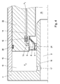
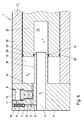
- Fig. 4 shows a further possible embodiment of the invention.
- the lifting element is designed as an elastic damping seal 24.
- the damping seal 24 is arranged on the recess 23 of the cylinder piston 22.
- the damping seal 24 is hollow and thus forms a volume between the cylinder piston 22 and the damper seal - the displacement 9.
- the damping seal 24 is compressed, as in Fig. 4 indicated by dashed lines.
- the damping seal 24 lifts off from the damping pin 18 and creates an annular venting channel 5 between the damping seal 24 and the damping pin 18, through which the air trapped in the damping volume 19 can flow out again.
- the displacement 9 is formed by the pressure load by the working pressure p 1 again a gas spring with progressive spring constant, which counteracts the compression of the damping seal 24.
- the function of this embodiment is therefore again identical to that with reference to Fig. 2 described.
- the displacement 9 is always acted upon by the working pressure p 1 .
- a back pressure p 3 is present on the vent side, whose level is lower than that of the ventilation side.
- the displacement 9 is connected in this embodiment via a connecting channel 14 and a channel 11 with the outlet channel 3, in which the venting pressure p 3 is applied.
- a check valve 12 is arranged that blocks p 3 in the direction of the venting pressure.
- the lifting element here again a damping piston 7, can be designed with piston surfaces of different sizes.
- the cylinder piston 22 ascends with the damping seal 21 onto the damping pin 18, the pressure p 2 in the damping volume 19 and the venting pressure p 3 in the outlet channel 3 are the same.
- the venting pressure p 3 is via the connecting channel 14, the check valve 12 and the channel 11 in the displacement 9 at. If the damping seal 21 closes off the damping volume 19, the venting pressure p 3 in the outlet channel 3 drops sharply. In displacement 9, however, this pressure is maintained due to the check valve 12.
Landscapes
- Engineering & Computer Science (AREA)
- Physics & Mathematics (AREA)
- Fluid Mechanics (AREA)
- Mechanical Engineering (AREA)
- General Engineering & Computer Science (AREA)
- Actuator (AREA)
- Fluid-Damping Devices (AREA)
Abstract
Description
- Die gegenständliche Erfindung betrifft einen Pneumatikzylinder mit einer selbsteinstellenden Endlagendämpfung mit einem Zylindergehäuse, in dem ein beweglicher Zylinderkolben angeordnet ist, der an einer Seite von einem Druck beaufschlagt ist und sich durch die Bewegung des Zylinderkolbens im Bereich der Endlage des Zylinderkolbens ein von der nicht druckbeaufschlagten Seite des Zylinderkolbens begrenztes Dämpfvolumen ausbildet, sowie ein Verfahren zur selbsteinstellenden Endlagendämpfung.
- In Hydraulik- oder Pneumatikzylindern wird oftmals eine Endlagendämpfung verwendet, um zu verhindern, dass der Kolben in der Endlage gegen das Zylindergehäuse oder gegen einen Anschlag schlägt. Ziel der Endlagendämpfung ist es folglich, die Geschwindigkeit einer bewegten Masse (Kolben + Last), deren Schwerpunkt in der Regel in der Zylinderachse liegt, auf ein Niveau zu verringern, bei der weder der Zylinder noch die Maschine, in der der Zylinder eingebaut ist, beschädigt oder durch eingeleitete Stöße beeinträchtigt wird.
- Bei einer bekannten Endlagendämpfung nach
Fig. 1 wird am Ende des Arbeitshubes, im Bereich des Endanschlags des Zylinderkolbens 22 ein Dämpfzapfen 18 durch eine Dämpfdichtung 21 in einer Ausnehmung 23 des Zylinderkolbens 22 geführt (strichliert angedeutet), wodurch eine zusätzliche Kammer in der nicht Druck beaufschlagten Zylinderseite geschaffen wird - das Dämpfvolumen 19. Das nun entstandene Dämpfvolumen 19 kann nur über eine vorgesehene, hier nicht dargestellte, Ventilnadel, z.B. im Zylinderdeckel 4, entweichen. Beim Einfahren des Zylinderkolbens 22 wird die Luft, die sich in dieser Kammer sammelt, komprimiert und durch die Bewegung des Kolbens an der Ventilnadel vorbeigeführt. Das Volumen kann aber nicht in derselben Zeit abgeführt werden, in der der Kolben einfährt, weshalb es in dieser Kammer zu einem Druckanstieg kommt. Der Kolben wird durch diesen Druck verzögert und soll dadurch nicht auf den Zylinderdeckel bzw. einen Endanschlag aufschlagen, sondern mit dem zeitverzögerten Entweichen der Luft langsam einfahren. Die Ventilnadel wird dabei bei Inbetriebnahme des Zylinders eingestellt. Diese Form der Endlagendämpfung ist in vielen Pneumatik- oder Hydraulikzylindern zu finden die eine Endlagendämpfung aufweisen, wie z.B. in einem kolbenstangenlosen Pneumatikzylinder 1 wie inFig. 1 dargestellt. Der Nachteil dieser Endlagendämpfung ist jedoch, dass durch die feste Einstellung der Ventilnadel nur eine bestimmte kinetische Energie abgebaut werden kann. Bei Veränderung der zu dämpfenden Masse m (z.B. weil sich die Last ändert) und/oder Geschwindigkeit v des Kolbens bedürfte es einer erneuten Einstellung, was aber in der Praxis nicht immer möglich ist bzw. aufwendig ist. Durch das komplexe Zusammenwirken von Masse, Geschwindigkeit und Endlagendruck ist die Einstellung der Endlagendämpfung zeitaufwändig und durch die hohe Stoßbeanspruchung im Bereich des mechanischen Endanschlages nicht ideal. Dadurch wird die Lebensdauer des Zylinders gemindert. Häufig wird die Einstellung auch unzureichend vorgenommen oder gar völlig vergessen, dadurch kommt es auch zum Schwingen in der Endlage und damit zu verlängerten Zykluszeiten. - Weiters sind wegabhängige Endlagendämpfungen bekannt, wie z.B. aus der
EP 949 422 A1 - Ebenfalls sind pneumatische Stoßdämpfer bekannt, z.B. aus der
DE 37 40 669 A1 , mit einem Auslassventil, über das die bei einer Dämpfungsbewegung des Kolbens komprimierte Luft ausgelassen wird. Dazu wird ein Ventilstößel durch den Arbeitsdruck und eine Federkraft vorgespannt. Wenn der Druck der komprimierten Luft die Vorspannung übersteigt, öffnet das Auslassventil schlagartig und die komprimierte Luft wird über eine Drossel entspannt. Um einen solchen Stoßdämpfer optimal betreiben zu können, ist eine Regelung vorgesehen, mit der der Vordruck, gegen den der Kolben bewegt wird, in Abhängigkeit von der Position des Kolbens geregelt wird. Mit einer solchen Regelung kann ein sich einstellende Dämpfung erzielt werden, allerdings nur unter hohem Aufwand für die Regelung. - Die gegenständliche Erfindung hat sich die Aufgabe gestellt, eine Endlagendämpfung eines Pneumatikzylinders, sowie ein zugehöriges Verfahren, anzugeben, die sich selbsttätig auf unterschiedliche Betriebsparameter, wie z.B. Masse, Geschwindigkeit und Arbeitsdruck, einstellt, um eine in einem weiten Bereich optimale Dämpfung zu erzielen und die einfach und kostengünstig ausgestaltet ist.
- Diese Aufgabe wird erfindungsgemäß dadurch gelöst, dass die Endlagendämpfung einen Hubraum umfasst, der von einem beweglichen Hubelement und einem Teil des Pneumatikzylinders begrenzt ist, wobei der Hubraum über einen Verbindungskanal mit dem den Zylinderkolben beaufschlagenden Arbeitsdruck oder dem in einem Auslasskanal anliegenden Entlüftungsdruck verbunden ist und das Hubelement über einen Dämpfkanal vom Druck im Dämpfvolumen beaufschlagt ist, im Verbindungskanal vor dem Hubraum ein Rückschlagventil angeordnet ist, das in Richtung des Arbeitsdruckes bzw. des Entlüftungsdruckes sperrt und dass ein Entlüftungskanal vorgesehen ist, der mit dem beweglichen Hubelement öffenbar ist und der mit einem Auslasskanal verbunden ist. Das erfindungsgemäße Verfahren ergibt sich dadurch, dass im Dämpfvolumen durch die Bewegung des Zylinderkolbens ein Dämpfdruck entsteht, mit dem ein Hubelement beaufschlagt wird, das Hubelement durch den Dämpfdruck gegen ein in einem Hubraum abgeschlossenes, mit dem Arbeitsdruck oder dem Entlüftungsdruck beaufschlagtes Druckmittelvolumen bewegt wird und durch die Bewegung des Hubelements ein Entlüftungskanal geöffnet wird. Durch diese Anordnung bzw. dieses Verfahren entsteht im Hubraum eine adaptive Gasfeder mit einer progressiven Federsteifigkeit, die vom Arbeitsdruck bzw. vom Entlüftungsdruck und vom Druck im Endlagendämpfraum abhängig ist. Dadurch wird der effektive Abströmquerschnitt abschnittsweise geöffnet, wodurch eine nahezu lineare Öffnungsfunktion vorhanden ist. Die Federkonstante dieser Gasfeder verändert sich dabei selbstständig in Abhängigkeit von den herrschenden Drücken und es wird eine gleich bleibende Dämpfwirkung auch bei unterschiedlichen Betriebsdrücken und unterschiedlichen kinetischen Energien erzielt. Vorteilhaft wird in der adaptiven Gasfeder der Entlüftungsdruck verwendet, da der Druckverlauf auf der Entlüftungsseite eine ausgeprägtere Abhängigkeit von der Verfahrgeschwindigkeit des Zylinderkolbens zeigt und damit als Regelgröße besser geeignet ist. Die Erfindung erhöht dadurch den Komfort, die Funktionssicherheit und die Nutzerfreundlichkeit des pneumatischen Antriebs. Durch die selbstständige Anpassung der Endlagendämpfung an die Betriebsbedingungen entfallen darüber hinaus auch die Kosten für die manuelle Einstellung und die Zykluszeiten verringern sich.
- Das Dämpfvolumen wird vorteilhaft gebildet, indem im Bereich des Endanschlags des Zylinderkolbens ein sich in axialer Richtung in das Zylindergehäuse erstreckender Dämpfzapfen angeordnet ist und der Zylinderkolben mit einer den Dämpfzapfen aufnehmbaren Ausnehmung ausgeführt ist. Dadurch wird das Zylindervolumen beim Einfahren des Dämpfzapfens in die Ausnehmung zur Ausbildung des Dämpfvolumens geteilt. Alternativ kann das Dämpfvolumen auch gebildet werden, indem ein Auslasskanal seitlich am Zylindergehäuse und axial beabstandet vom Zylinderdeckel angeordnet wird.
- In einer bevorzugten Ausgestaltung ist das Hubelement als im Hubraum geführt gelagerter Dämpfkolben ausgeführt. Der Hubraum bzw. der Dämpfkolben kann dabei, je nach konstruktiver Ausgestaltung, entweder in einen den Pneumatikzylinder abschließenden Zylinderdeckel oder im Zylinderkolben angeordnet sein.
- Das Hubelement kann aber alternativ auch ein Dichtelement zwischen Dämpfzapfen und Zylinderkolben sein, wobei das Dichtelement hohl ist und im Zylinderkolben angeordnet ist. Mit einer solchen Anordnung kann die Anzahl der benötigten Komponenten für die Endlagendämpfung reduziert werden.
- Um ein mögliches Schwingen des Zylinderkolbens beim Auffahren auf das im Dämpfvolumen eingesperrte Luftvolumen zu vermeiden bzw. zu reduzieren, kann am Pneumatikzylinder eine Entlüftungsöffnung vorgesehen sein, die mit dem Dämpfvolumen verbunden ist.
- Die gegenständliche Erfindung wird im Nachfolgenden anhand der schematischen, nicht einschränkenden, bevorzugte Ausgestaltungen der Erfindung zeigenden
Figuren 1 bis 4 beschrieben. Dabei zeigt -
Fig. 1 einen bekannten kolbenstangenlosen Pneumatikzylinder, -
Fig. 2 eine Ausführung der Erfindung mit der Endlagendämpfung im Zylinderdeckel, -
Fig. 3 eine Ausführung der Erfindung mit der Endlagendämpfung im Zylinderkolben, -
Fig. 4 eine Ausführung der Endlagendämpfung als Dämpfdichtung und -
Fig. 5 eine Ausführung der Erfindung mit Druckversorgung der adaptiven Gasfeder von der Entlüftungsseite. - In
Fig. 2 ist ein Endbereich, hier das durch den Zylinderdeckel 4 abgeschlossene Ende, eines Pneumatikzylinders 1, hier z.B. eines kolbenstangenlosen Pneumatikzylinders, mit einer erfindungsgemäßen selbsteinstellenden Endlagendämpfung im Detail gezeigt. Der Zylinderkolben 22 ist, z.B. über einen Schlitten, mit einer Masse m verbunden und bewegt sich unter Druckbeaufschlagung p1 an einer seiner Seiten mit einer Geschwindigkeit v in einem Zylindergehäuse 15 in Richtung des mechanischen Endanschlags (im Bereich des Zylinderdeckels 4). Der Zylinderkolben 22 ist gegenüber dem Zylindergehäuse in bekannter Weise mittels Dichtelementen 20 abgedichtet. Die Bewegungsrichtung ist inFig. 2 durch den Pfeil angedeutet. Die durch die Bewegung verdrängte Luft auf der nicht druckbeaufschlagten Seite des Zylinderkolbens 22 wird dabei über einen Kanal 3 im Zylinderdeckel 4 und einen hier nicht dargestellten Anschluss abgeführt. - Im Zylinderkolben 22 ist eine Ausnehmung 23 vorgesehen, die einen sich axial in das Zylindergehäuse 15 erstreckenden Dämpfzapfen 18 aufnehmen kann. Der Dämpfzapfen 18 ist in diesem Beispiel am Zylinderdeckel 4 und im Endbereich bzw. im Bereich einer Endlage des Zylinderkolbens 22 des Pneumatikzylinders 1 angeordnet, wodurch sich ein Dämpfbereich ergibt. Ein Auslasskanal 3 erstreckt sich hier in axialer Richtung durch den Zylinderdeckel 4 und durch den Dämpfzapfen 18. Ein solches Dämpfvolumen 19 kann natürlich auch anders, insbesondere ohne Dämpfzapfen 18, gebildet werden, z.B. indem der Auslasskanal 3 seitlich und in axialer Richtung beabstandet vom Zylinderdeckel 4 am Zylindergehäuse 15 angeordnet wird, wie in
Fig. 2 strichliert angedeutet und durch Bezugszeichen 3a gekennzeichnet. Dadurch wird der Auslasskanal 3a bei der Bewegung des Zylinderkolbens 22 verschlossen, wodurch sich im Bereich der Endlage des Zylinderkolbens 22 zwischen Zylinderdeckel 4 und Zylinderkolben 22 wieder ein entsprechendes Dämpfvolumen 19 ergibt. - Im Zylinderdeckel 4 ist ein Hubraum 9 vorgesehen - hier eine einfache Bohrung, die durch eine Scheibe 10 verschlossen wird. Der Hubraum 9 wird durch ein Hubelement, hier ein Dämpfkolben 7, begrenzt, das beweglich (wie durch den Doppelpfeil in
Fig. 2 angedeutet) und geführt im Hubraum 9 angeordnet ist. Der Hubraum 9 ist hier über einen Kanal 11 im Zylinderdeckel 4 und einen im Zylindergehäuse 15 angeordneten Verbindungskanal 14 mit dem Arbeitsdruck p1 auf der druckbeaufschlagten Seite des Zylinderkolbens 22 verbunden. Im Verbindungskanal 14 oder alternativ wie in diesem Beispiel im Kanal 11 im Zylinderdeckel 4 ist ein Rückschlagventil 12 angeordnet, dass in Richtung des Arbeitsdruckes p1 sperrt. Der Dämpfkolben 7 wird daher an einer Seite durch den im Hubraum 9 wirkenden Arbeitsdruck p1 druckbeaufschlagt. Die gegenüberliegende Seite 6 des Dämpfkolbens 7 ist in diesem Beispiel abgestuft ausgeführt und ist über einen Dämpfkanal 16 mit dem Dämpfvolumen 19 verbunden. Der Dämpfkolben 7 verschließt einen im Zylinderdeckel 4 angeordneten Entlüftungskanal 5, der mit dem Auslasskanal 3 verbunden ist. Der Dämpfkolben 7 kann zur Abdichtung gegenüber dem Zylinderdeckel 4 mit Drosselnuten 8 versehene sein. Anstelle der Drosselnuten 8 können aber auch beliebige andere Dichtelemente vorgesehen sein. Um bei einer Arbeitsdruckänderung von einem Hub zum nächsten den neuen Arbeitsdruck p1 im Hubraum 9 einstellen zu können, kann über die Drosselnuten 8 oder den anderen Dichtelementen an dieser Stelle zum Druckabbau im Hubraum 9 auch eine gezielte Leckage vorgesehen sein. Ebenso ist aber natürlich denkbar, den Hubraum 9 zwischen zwei Hüben wenn notwendig über andere geeignete Einrichtungen, wie z.B. ein Ventil oder eine Drossel, zu entlüften bzw. mit dem neuen Arbeitsdruck p1 zu beaufschlagen. - Eine solche Endlagendämpfung kann natürlich auch an der anderen Seite des Pneumatikzylinders vorgesehen sein, so dass auch die entgegen gesetzte Bewegung entsprechend endlagengedämpft ist. Dazu kann dieselbe Anordnung auch auf der anderen Seite vorgesehen sein und der dann wirkende Arbeitsdruck wird über den zweiten Verbindungskanal 2 dem zweiten Hubraum 9 zugeführt.
- Im Nachfolgenden wird nun die Funktion der erfindungsgemäßen Endlagendämpfung beschrieben.
- Während der Bewegung des Zylinderkolbens 22 wird die verdrängte Luft auf der der druckbeaufschlagt Seite abgewandten Seite des Zylinderkolbens 22 durch den Auslasskanal 3 abgeführt. Der Auslasskanal 3 ist dabei vorteilhaft so dimensioniert, dass die gesamte verdrängte Luft ohne Rückstau (und damit ohne einhergehenden Druckanstieg) abgeführt werden kann. Wenn der Zylinderkolben 22 im Bereich der Endlage des Zylinderkolben 22 durch die Bewegung auf den Dämpfzapfen 18 auffährt, wird dieser durch eine in der Ausnehmung 23 des Zylinderkolbens 22 angeordnete Dämpfdichtung 21 geführt, wodurch der Zylinderraum durch die Dämpfdichtung 21 geteilt wird. Dadurch entsteht am Ende der Bewegung des Zylinderkolbens 22 eine abgeschlossene Kammer - das Dämpfvolumen 19, in dem die darin verbleibende Luft zur Dämpfung des Zylinderkolbens 22 durch dessen Bewegung komprimiert wird. Dieser Dämpfdruck p2 im Dämpfvolumen 19 wirkt über den Dämpfkanal 16 auf die Seite 6 des Dämpfkolbens 7, dessen dem Hubraum 9 zugewandte Seite gleichzeitig über den Verbindungskanal 14 mit dem Arbeitsdruck p1 beaufschlagt ist. Übersteigt der Dämpfdruck p2 im Dämpfvolumen 19 durch die weitere Bewegung des Zylinderkolbens 22 nun den Arbeitsdruck p1 wird der Dämpfkolben 7 angehoben, wodurch die Luft im Hubraum 9 komprimiert wird, da durch das Rückschlagventil 12 ein Zurückströmen der Luft verhindert wird. Durch den Hub des Dämpfkolbens 7 wird der Entlüftungskanal 5 geöffnet und die im Dämpfvolumen 19 eingeschlossene Luft beginnt über den Dämpfkanal 16, den Entlüftungskanal 5 und den Abströmkanal 3 abzuströmen. Durch das im Hubraum 9 eingeschlossene Luftvolumen entsteht im Hubraum 9 eine Gasfeder mit einer progressiven Federsteifigkeit

mit AK der Fläche des Dämpfkolbens, V dem eingeschlossenen Volumen, das von den wirkenden Drücken abhängig ist, und EL, dem Elastizitätsmodul der Luft, der sich ergibt aus P*n, dem Druck multipliziert mit dem Polytropenexponent. Diese adaptive Gasfeder wirkt dem Hub des Dämpfelements 7 entgegen, wodurch der Abströmquerschnitt nicht schlagartig, sondern progressiv und in Abhängigkeit vom herrschenden Arbeitsdruck p1 geöffnet wird. Dabei verhält sich die Öffnungsfunktion annähernd linear zum Druck. Die Federkonstante dieser Gasfeder wird durch das Volumen und den Druck des Luftvolumens bestimmt. Wird der Arbeitsdruck variiert, ändert sich damit auch die Federkonstante der Gasfeder. Ändert sich die kinetische Energie des Zylinderkolbens 22, z.B. durch eine höhere Geschwindigkeit v oder eine andere Masse m, passt sich über unterschiedliche Druckverhältnisse der Hub des Dämpfelementes 7 und damit auch das Dämpfverhalten selbstständig an die neuen Gegebenheiten an. Dies funktioniert in einem gewissen Energiebereich, wobei die maximale Dämpfenergie nicht überschritten werden darf. Bei unterschiedlichen Arbeitsdrücken verschiebt sich die Kennlinie der Dämpffunktion. - Wird der Öffnungsdruck im Dämpfraum 19 nicht erreicht, z.B. durch sehr niedrige Geschwindigkeiten beim Transport sehr kleiner Massen, besteht die Gefahr des Schwingens. Das Schwingen entsteht durch das Auffahren des Zylinderkolbens 22 auf das Luftpolster, das im Dämpfraum 19 gebildet wird, da die eingesperrte Luft nicht entweichen kann. Diesem Schwingen kann z.B. durch gezieltes Einbringen einer (oder mehrerer) Entlüftungsöffnung(en) 17, z.B. im Dämpfzapfen 18 oder im Zylindergehäuse 15, entgegengewirkt werden. Die Entlüftungsöffnung 17 kann dabei in ihrer Form, Lage und Größe den Gegebenheiten, z.B. der konstruktiven Ausgestaltung oder den zu erwartenden kinetischen Energien, angepasst werden.
- In
Fig. 3 ist eine alternative Ausgestaltung einer erfindungsgemäßen selbsteinstellenden Endlagendämpfung gezeigt. In dieser Ausführung ist der Hubraum 9 im Zylinderkolben 22 angeordnet, ebenso wie der Verbindungskanal 14, das Rückschlagventil 12, der Dämpfkanal 16 und der Entlüftungskanal 5. Ansonsten ist die Funktion dieser Endlagendämpfung identisch mit der unter Bezug aufFig. 2 beschriebenen. -
Fig. 4 zeigt eine weitere mögliche Ausgestaltung der Erfindung. In diesem Beispiel ist das Hubelement als elastische Dämpfdichtung 24 ausgeführt. Die Dämpfdichtung 24 ist dabei an der Ausnehmung 23 des Zylinderkolbens 22 angeordnet. Die Dämpfdichtung 24 ist dabei hohl ausgeführt und bildet somit ein Volumen zwischen dem Zylinderkolben 22 und der Dämpfdichtung - den Hubraum 9. Beim Auffahren des Zylinderkolbens 22 auf den Dämpfzapfen 18 teilt die Dämpfdichtung 24 wieder das Zylindervolumen, wodurch wieder das Dämpfvolumen 19 entsteht. Durch die weitere Bewegung des Zylinderkolbens 22 und der damit verbundenen Druckerhöhung im Dämpfraum 19 wird die Dämpfdichtung 24 zusammengedrückt, wie inFig. 4 strichliert angedeutet. Dadurch hebt die Dämpfdichtung 24 vom Dämpfzapfen 18 ab und es entsteht ein ringförmiger Entlüftungskanal 5 zwischen Dämpfdichtung 24 und Dämpfzapfen 18, durch den die im Dämpfvolumen 19 eingesperrte Luft wieder abströmen kann. Im Hubraum 9 wird durch die Druckbelastung durch den Arbeitsdruck p1 wieder eine Gasfeder mit progressiver Federkonstante gebildet, die dem Zusammendrücken der Dämpfdichtung 24 entgegen wirkt. Die Funktion dieser Ausführung ist daher wieder identisch mit der unter Bezug aufFig. 2 beschriebenen. - In den obigen Ausführungsbeispielen wird der Hubraum 9 immer durch den Arbeitsdruck p1 beaufschlagt. Es ist aber auch denkbar, den Hubraum 9 bzw. die adaptive Gasfeder von der Entlüftungsseite her zu beaufschlagen, wie nachfolgen anhand der
Fig. 5 beschrieben wird. Auf Grund der üblichen Abluftdrosselung zur Geschwindigkeitsregulierung des Zylinderkolbens 22 ist auf der Entlüftungsseite ein Gegendruck p3 vorhanden, dessen Niveau niedriger ist als das der Belüftungsseite. Der Hubraum 9 wird in dieser Ausgestaltung über einen Verbindungskanal 14 und einem Kanal 11 mit dem Auslasskanal 3 verbunden, in dem der Entlüftungsdruck p3 anliegt. Im Verbindungskanal 14 bzw. im Kanal 11 ist wiederum ein Rückschlagventil 12 angeordnet, dass in Richtung des Entlüftungsdruckes p3 sperrt. Zum Ausgleich des nun niedrigeren Drucks im Hubraum 9 der adaptiven Gasfeder kann das Hubelement, hier wieder ein Dämpfkolben 7, mit unterschiedlich großen Kolbenflächen ausgeführt werden. Bis der Zylinderkolben 22 mit der Dämpfdichtung 21 auf den Dämpfzapfen 18 auffährt, sind der Druck p2 im Dämpfvolumen 19 und der Entlüftungsdruck p3 im Auslasskanal 3 gleich groß. Der Entlüftungsdruck p3 steht über den Verbindungskanal 14, das Rückschlagventil 12 und dem Kanal 11 auch im Hubraum 9 an. Schließt die Dämpfdichtung 21 das Dämpfvolumen 19 ab, fällt der Entlüftungsdruck p3 im Auslasskanal 3 stark ab. Im Hubraum 9 hingegen, bleibt dieser Druck auf Grund des Rückschlagventils 12 erhalten. Am Dämpfkolben 7 steht auf Seite 6 steht wieder der ansteigende Druck p2 im Dämpfvolumen 19 an und auf der anderen Seite des Dämpfkolbens 7 der Entlüftungsdruck p3 vor Dämpfbeginn. Ansonsten ist die Funktion dieser Endlagendämpfung identisch mit der unter Bezug aufFig. 2 beschriebenen, wobei die adaptive Gasfeder nun vom Entlüftungsdruck p3 abhängig ist. - Selbstverständlich können die adaptiven Gasfedern der Endlagendämpfungen gemäß den Ausführungen nach den
Figuren 3 und4 wie oben beschrieben ebenfalls von der Entlüftungsseite, d.h. durch den Entlüftungsdruck p3, beaufschlagt werden. - Die obigen Beispiele wurden zwar mit Luft als Druckmittel beschrieben, es ist aber selbstverständlich ebenso möglich, anstelle von Luft ein beliebiges anderes geeignetes Gas als Druckmittel zu verwenden.
Claims (10)
- Pneumatikzylinder mit einer selbsteinstellenden Endlagendämpfung mit einem Zylindergehäuse (15), in dem ein beweglicher Zylinderkolben (22) angeordnet ist, der an einer Seite von einem Arbeitsdruck (p1) beaufschlagt ist und sich durch die Bewegung des Zylinderkolbens (22) im Bereich der Endlage des Zylinderkolbens (22) ein von der nicht druckbeaufschlagten Seite des Zylinderkolbens (22) begrenztes Dämpfvolumen (19) ausbildet, dadurch gekennzeichnet, dass die Endlagendämpfung einen Hubraum (9) umfasst, der von einem beweglichen Hubelement (7, 24) und einem Teil des Pneumatikzylinders (1) begrenzt ist, wobei der Hubraum (9) über einen Verbindungskanal (14) mit dem den Zylinderkolben (22) beaufschlagenden Arbeitsdruck (p1) oder dem in einem Auslasskanal (3) anliegenden Entlüftungsdruck (p3) verbunden ist und das Hubelement (7, 24) über einen Dämpfkanal (16) vom Dämpfdruck (p2) im Dämpfvolumen (19) beaufschlagt ist, dass im Verbindungskanal (14) vor dem Hubraum (9) ein Rückschlagventil (12) angeordnet ist, das in Richtung des Arbeitsdruckes (p1) bzw. des Entlüftungsdruckes (p3) sperrt und dass ein Entlüftungskanal (5) vorgesehen ist, der mit dem beweglichen Hubelement (7, 24) öffenbar ist und der mit dem Auslasskanal (3) verbunden ist.
- Pneumatikzylinder nach Anspruch 1, dadurch gekennzeichnet, dass im Bereich des Endanschlags des Zylinderkolbens (22) ein sich in axialer Richtung in das Zylindergehäuse (15) erstreckender Dämpfzapfen (18) angeordnet ist und der Zylinderkolben (22) mit einer den Dämpfzapfen (18) aufnehmbaren Ausnehmung (23) ausgeführt ist.
- Pneumatikzylinder nach Anspruch 1, dadurch gekennzeichnet, dass ein Auslasskanal (3) seitlich am Zylindergehäuse (15) und axial beabstandet von einem Zylinderdeckel (4) angeordnet ist.
- Pneumatikzylinder nach einem der Ansprüche 1 bis 3, dadurch gekennzeichnet, dass das Hubelement als ein im Hubraum (9) geführt gelagerter Dämpfkolben (7) ausgeführt ist.
- Pneumatikzylinder nach Anspruch 4, dadurch gekennzeichnet, dass der Hubraum (9) in einem den Pneumatikzylinder (1) abschließenden Zylinderdeckel (4) angeordnet ist.
- Pneumatikzylinder nach Anspruch 4, dadurch gekennzeichnet, dass der Hubraum (9) im Zylinderkolben (22) angeordnet ist.
- Pneumatikzylinder nach Anspruch 2, dadurch gekennzeichnet, dass als Hubelement ein elastisches Dichtelement (24) zwischen Dämpfzapfen (18) und Zylinderkolben (22) vorgesehen ist, wobei das Dichtelement (24) hohl ist und im Zylinderkolben (22) angeordnet ist.
- Pneumatikzylinder nach einem der Ansprüche 1 bis 7, dadurch gekennzeichnet, dass am Pneumatikzylinder (1) eine Entlüftungsöffnung (17) vorgesehen ist, die mit dem Dämpfvolumen (19) verbunden ist.
- Pneumatikzylinder nach einem der Ansprüche 1 bis 8, dadurch gekennzeichnet, dass an beiden Endlagen des Zylinderkolbens (22) eine selbsteinstellende Endlagendämpfung angeordnet ist.
- Verfahren zur selbsteinstellenden Endlagendämpfung eines in einem Zylindergehäuse (15) bewegten Zylinderkolben (22) eines Pneumatikzylinders (1), der an einer Seite von einem Arbeitsdruck (p1) beaufschlagt wird und wobei durch die Bewegung des Zylinderkolbens (22) im Bereich der Endlage des Zylinderkolbens (22) ein von der nicht druckbeaufschlagten Seite des Zylinderkolbens (22) begrenztes Dämpfvolumen (19) gebildet wird, dadurch gekennzeichnet, dass im Dämpfvolumen (19) durch die Bewegung des Zylinderkolbens (22) ein Dämpfdruck (p2) entsteht, mit dem ein Hubelement (7, 24) beaufschlagt wird, dass das Hubelement (7, 24) durch den Dämpfdruck (p2) gegen ein mit dem Arbeitsdruck (p1) oder dem Entlüftungsdruck (p3) beaufschlagtes abgeschlossenes Druckmittelvolumen bewegt wird und dass durch die Bewegung des Hubelements (7, 24) ein Entlüftungskanal (5) geöffnet wird.
Applications Claiming Priority (2)
| Application Number | Priority Date | Filing Date | Title |
|---|---|---|---|
| AT8282007A AT504592B1 (de) | 2007-05-24 | 2007-05-24 | Pneumatikzylinder mit einer und verfahren zur selbsteinstellenden endlagendämpfung |
| AT7142008A AT505441B1 (de) | 2007-05-24 | 2008-05-05 | Pneumatikzylinder mit einer und verfahren zur selbsteinstellenden endlagendämpfung |
Publications (3)
| Publication Number | Publication Date |
|---|---|
| EP1998054A2 true EP1998054A2 (de) | 2008-12-03 |
| EP1998054A3 EP1998054A3 (de) | 2012-08-15 |
| EP1998054B1 EP1998054B1 (de) | 2014-08-13 |
Family
ID=39829770
Family Applications (1)
| Application Number | Title | Priority Date | Filing Date |
|---|---|---|---|
| EP08156234.0A Not-in-force EP1998054B1 (de) | 2007-05-24 | 2008-05-15 | Pneumatikzylinder mit einer selbsteinstellenden Endlagendämpfung und entsprechendes Verfahren |
Country Status (2)
| Country | Link |
|---|---|
| US (1) | US8596431B2 (de) |
| EP (1) | EP1998054B1 (de) |
Cited By (3)
| Publication number | Priority date | Publication date | Assignee | Title |
|---|---|---|---|---|
| CN102235400A (zh) * | 2010-04-22 | 2011-11-09 | 郑文瑞 | 缓冲装置 |
| DE102011051400B3 (de) * | 2011-06-28 | 2012-06-06 | Parker Hannifin Gmbh | Pneumatikzylinder mit selbstjustierender Endlagendämpfung |
| DE102016002705A1 (de) * | 2016-03-05 | 2017-09-07 | Wabco Gmbh | Pneumatische Schaltvorrichtung eines automatisierten Schaltgetriebes |
Families Citing this family (6)
| Publication number | Priority date | Publication date | Assignee | Title |
|---|---|---|---|---|
| JP5960034B2 (ja) * | 2012-11-21 | 2016-08-02 | 株式会社ショーワ | 圧力緩衝装置および懸架装置 |
| CN103104572A (zh) * | 2012-12-11 | 2013-05-15 | 江苏锐成机械有限公司 | 一种高速机床用防撞液压缸 |
| US20150076753A1 (en) * | 2013-09-19 | 2015-03-19 | Dadco, Inc. | Overtravel Pressure Relief For A Gas Spring |
| US9447834B2 (en) * | 2013-09-19 | 2016-09-20 | Dadco, Inc. | Overtravel pressure relief for a gas spring |
| CN103821790A (zh) * | 2013-11-29 | 2014-05-28 | 安徽凯信机电科技有限公司 | 一种带有缓冲机构的液压缸 |
| JP7447689B2 (ja) * | 2020-06-10 | 2024-03-12 | Smc株式会社 | ガスシリンダ |
Citations (2)
| Publication number | Priority date | Publication date | Assignee | Title |
|---|---|---|---|---|
| DE3740669A1 (de) | 1987-12-01 | 1989-06-15 | Festo Kg | Pneumatischer stossdaempfer |
| EP0949422A1 (de) | 1998-03-04 | 1999-10-13 | Bümach Engineering International B.V. | Endlagendämpfung |
Family Cites Families (83)
| Publication number | Priority date | Publication date | Assignee | Title |
|---|---|---|---|---|
| DE1039844B (de) * | 1957-05-23 | 1958-09-25 | Pumpenfabrik Urach | Hydraulischer Arbeitszylinder mit Daempfungseinrichtung |
| FR1527946A (fr) * | 1967-04-05 | 1968-06-07 | Cie Parisienne Outil Air Compr | Perfectionnement aux vérins à amortissement |
| SE346468B (de) * | 1969-02-24 | 1972-07-10 | Lkb Medical Ab | |
| US3613503A (en) | 1969-04-28 | 1971-10-19 | Cessna Aircraft Co | Hydraulic cylinder with pressure control |
| US3889576A (en) * | 1969-06-13 | 1975-06-17 | Sheffer Corp | Locking cylinder with improved locking structure |
| FR2138342B1 (de) * | 1971-05-24 | 1974-03-08 | Poclain Sa | |
| GB1351958A (en) * | 1971-09-14 | 1974-05-15 | Martonair Ltd | Pneumatic actuators |
| FR2182672B1 (de) * | 1972-05-03 | 1975-03-21 | Poclain Sa | |
| NL182162C (nl) | 1977-01-10 | 1988-01-18 | Hydraudyne Bv | Inrichting voor het hydraulisch of pneumatisch aandrijven en afremmen van een werktuig. |
| ES226859Y (es) * | 1977-03-03 | 1977-11-16 | Marcapasos cardiaco de ritmo controlado por senales de regu-lacion detectadas en las vias yno los receptores nerviosos. | |
| JPS57103947A (en) * | 1980-12-18 | 1982-06-28 | Kuroda Precision Ind Ltd | Pneumatic shock absorber |
| JPS63143392A (ja) * | 1986-12-05 | 1988-06-15 | Toyota Autom Loom Works Ltd | ワツブル式可変容量圧縮機の制御方法 |
| US4830003A (en) * | 1988-06-17 | 1989-05-16 | Wolff Rodney G | Compressive stent and delivery system |
| SE467424B (sv) * | 1990-11-09 | 1992-07-13 | Mecman Ab | Anordning foer aendlaegesdaempning och hastighetsreglering av roerelsen hos en kolv i en tryckmediecylinder |
| US5437285A (en) * | 1991-02-20 | 1995-08-01 | Georgetown University | Method and apparatus for prediction of sudden cardiac death by simultaneous assessment of autonomic function and cardiac electrical stability |
| US5403341A (en) * | 1994-01-24 | 1995-04-04 | Solar; Ronald J. | Parallel flow endovascular stent and deployment apparatus therefore |
| US6039749A (en) * | 1994-02-10 | 2000-03-21 | Endovascular Systems, Inc. | Method and apparatus for deploying non-circular stents and graftstent complexes |
| JPH0893719A (ja) * | 1994-09-20 | 1996-04-09 | Futaba Denki Kogyo Kk | 油圧又は空圧シリンダのストローク調節装置 |
| US5707400A (en) * | 1995-09-19 | 1998-01-13 | Cyberonics, Inc. | Treating refractory hypertension by nerve stimulation |
| DE29517364U1 (de) * | 1995-11-02 | 1996-01-04 | Festo Kg | Vorrichtung zur Endlagendämpfung |
| US5727558A (en) * | 1996-02-14 | 1998-03-17 | Hakki; A-Hamid | Noninvasive blood pressure monitor and control device |
| SE510463C2 (sv) * | 1996-11-26 | 1999-05-25 | Pos Line Ab | Förfarande och anordning för att eliminera kolvstångsrusning vid start av pneumatisk motor |
| GB9710905D0 (en) * | 1997-05-27 | 1997-07-23 | Imperial College | Stent for blood vessel |
| CH691846A5 (fr) * | 1997-06-20 | 2001-11-15 | Ecole Polytech | Implant de dilatation intravasculaire à déflecteur. |
| US6663617B1 (en) * | 1998-05-28 | 2003-12-16 | Georgia Tech Research Corporation | Devices for creating vascular grafts by vessel distension using fixed post and moveable driver elements |
| US6413273B1 (en) * | 1998-11-25 | 2002-07-02 | Israel Aircraft Industries Ltd. | Method and system for temporarily supporting a tubular organ |
| US6442424B1 (en) * | 1999-05-26 | 2002-08-27 | Impulse Dynamics N.V. | Local cardiac motion control using applied electrical signals |
| EP1072282A1 (de) * | 1999-07-19 | 2001-01-31 | EndoArt S.A. | Durchflusskontrollvorrichtuing |
| US6375666B1 (en) * | 1999-12-09 | 2002-04-23 | Hans Alois Mische | Methods and devices for treatment of neurological disorders |
| US6458153B1 (en) * | 1999-12-31 | 2002-10-01 | Abps Venture One, Ltd. | Endoluminal cardiac and venous valve prostheses and methods of manufacture and delivery thereof |
| US6764498B2 (en) * | 1999-12-09 | 2004-07-20 | Hans Alois Mische | Methods and devices for treatment of neurological disorders |
| US7499742B2 (en) * | 2001-09-26 | 2009-03-03 | Cvrx, Inc. | Electrode structures and methods for their use in cardiovascular reflex control |
| US6522926B1 (en) * | 2000-09-27 | 2003-02-18 | Cvrx, Inc. | Devices and methods for cardiovascular reflex control |
| US7623926B2 (en) * | 2000-09-27 | 2009-11-24 | Cvrx, Inc. | Stimulus regimens for cardiovascular reflex control |
| US8086314B1 (en) * | 2000-09-27 | 2011-12-27 | Cvrx, Inc. | Devices and methods for cardiovascular reflex control |
| US6985774B2 (en) * | 2000-09-27 | 2006-01-10 | Cvrx, Inc. | Stimulus regimens for cardiovascular reflex control |
| US7158832B2 (en) * | 2000-09-27 | 2007-01-02 | Cvrx, Inc. | Electrode designs and methods of use for cardiovascular reflex control devices |
| US20080167699A1 (en) * | 2000-09-27 | 2008-07-10 | Cvrx, Inc. | Method and Apparatus for Providing Complex Tissue Stimulation Parameters |
| US7616997B2 (en) * | 2000-09-27 | 2009-11-10 | Kieval Robert S | Devices and methods for cardiovascular reflex control via coupled electrodes |
| US6681136B2 (en) * | 2000-12-04 | 2004-01-20 | Science Medicus, Inc. | Device and method to modulate blood pressure by electrical waveforms |
| US6585753B2 (en) * | 2001-03-28 | 2003-07-01 | Scimed Life Systems, Inc. | Expandable coil stent |
| US7163553B2 (en) * | 2001-12-28 | 2007-01-16 | Advanced Cardiovascular Systems, Inc. | Intravascular stent and method of use |
| CN1652841A (zh) * | 2002-03-14 | 2005-08-10 | 布雷恩斯盖特有限公司 | 血压调节技术 |
| ATE369820T1 (de) * | 2002-09-04 | 2007-09-15 | Endoart Sa | Chirurgischer ring mit fernsteuerungseinrichtung für reversible durchmesserveränderungen |
| ES2295272T3 (es) * | 2002-09-04 | 2008-04-16 | Endoart S.A. | Sistema de cierre para anillo quirurgico. |
| US7901419B2 (en) * | 2002-09-04 | 2011-03-08 | Allergan, Inc. | Telemetrically controlled band for regulating functioning of a body organ or duct, and methods of making, implantation and use |
| DE10246766B3 (de) | 2002-10-07 | 2004-07-01 | Bosch Rexroth Ag | Endlagengedämpfter Pneumatikzylinder |
| US7647931B2 (en) * | 2002-12-30 | 2010-01-19 | Quiescence Medical, Inc. | Stent for maintaining patency of a body region |
| US7044981B2 (en) * | 2003-01-22 | 2006-05-16 | Boston Scientific Scimed, Inc. | Ureteral stent configured for improved patient comfort and aftercare |
| US9271825B2 (en) * | 2003-02-06 | 2016-03-01 | Mike Arkusz | Pulsating stent graft |
| JP4054990B2 (ja) * | 2003-03-07 | 2008-03-05 | Smc株式会社 | シリンダ装置 |
| US20060111626A1 (en) * | 2003-03-27 | 2006-05-25 | Cvrx, Inc. | Electrode structures having anti-inflammatory properties and methods of use |
| US7201772B2 (en) * | 2003-07-08 | 2007-04-10 | Ventor Technologies, Ltd. | Fluid flow prosthetic device |
| US7479157B2 (en) * | 2003-08-07 | 2009-01-20 | Boston Scientific Scimed, Inc. | Stent designs which enable the visibility of the inside of the stent during MRI |
| US7502650B2 (en) * | 2003-09-22 | 2009-03-10 | Cvrx, Inc. | Baroreceptor activation for epilepsy control |
| US7480532B2 (en) * | 2003-10-22 | 2009-01-20 | Cvrx, Inc. | Baroreflex activation for pain control, sedation and sleep |
| US7706884B2 (en) * | 2003-12-24 | 2010-04-27 | Cardiac Pacemakers, Inc. | Baroreflex stimulation synchronized to circadian rhythm |
| US7486991B2 (en) * | 2003-12-24 | 2009-02-03 | Cardiac Pacemakers, Inc. | Baroreflex modulation to gradually decrease blood pressure |
| US7643875B2 (en) * | 2003-12-24 | 2010-01-05 | Cardiac Pacemakers, Inc. | Baroreflex stimulation system to reduce hypertension |
| US7869881B2 (en) * | 2003-12-24 | 2011-01-11 | Cardiac Pacemakers, Inc. | Baroreflex stimulator with integrated pressure sensor |
| KR20050071956A (ko) * | 2004-01-05 | 2005-07-08 | 삼성전자주식회사 | 반도체 메모리 소자 및 제조 방법 |
| DE102004012083A1 (de) * | 2004-03-12 | 2005-09-29 | Bosch Rexroth Teknik Ab | Druckmittelzylinder |
| US8003122B2 (en) * | 2004-03-31 | 2011-08-23 | Cordis Corporation | Device for local and/or regional delivery employing liquid formulations of therapeutic agents |
| WO2006012033A2 (en) * | 2004-06-30 | 2006-02-02 | Cvrx, Inc. | Lockout connector arrangement for implantable medical device |
| US20060004417A1 (en) * | 2004-06-30 | 2006-01-05 | Cvrx, Inc. | Baroreflex activation for arrhythmia treatment |
| WO2006012050A2 (en) * | 2004-06-30 | 2006-02-02 | Cvrx, Inc. | Connection structures for extra-vascular electrode lead body |
| US7373204B2 (en) * | 2004-08-19 | 2008-05-13 | Lifestim, Inc. | Implantable device and method for treatment of hypertension |
| US20060074453A1 (en) * | 2004-10-04 | 2006-04-06 | Cvrx, Inc. | Baroreflex activation and cardiac resychronization for heart failure treatment |
| US7395119B2 (en) * | 2005-05-19 | 2008-07-01 | Cvrx, Inc. | Implantable electrode assembly having reverse electrode configuration |
| US20080114439A1 (en) * | 2005-06-28 | 2008-05-15 | Venkatesh Ramaiah | Non-occluding dilation device |
| US8923972B2 (en) * | 2005-07-25 | 2014-12-30 | Vascular Dynamics, Inc. | Elliptical element for blood pressure reduction |
| EP1962949B1 (de) * | 2005-12-20 | 2015-02-25 | The Cleveland Clinic Foundation | Vorrichtung zur modulation des baroreflexsystems |
| US9026215B2 (en) * | 2005-12-29 | 2015-05-05 | Cvrx, Inc. | Hypertension treatment device and method for mitigating rapid changes in blood pressure |
| US20080004673A1 (en) * | 2006-04-03 | 2008-01-03 | Cvrx, Inc. | Implantable extravascular electrostimulation system having a resilient cuff |
| JP2009537281A (ja) * | 2006-05-19 | 2009-10-29 | シーブイレクス インコーポレイテッド | 圧反射活性化と薬物治療を併用した生理反応の特性解析および調節 |
| US20080009916A1 (en) * | 2006-05-19 | 2008-01-10 | Cvrx, Inc. | Applications of heart rate variability analysis in electrotherapy affecting autonomic nervous system response |
| US20080046054A1 (en) * | 2006-06-23 | 2008-02-21 | Cvrx, Inc. | Implantable electrode assembly utilizing a belt mechanism for sutureless attachment |
| US8620422B2 (en) * | 2006-09-28 | 2013-12-31 | Cvrx, Inc. | Electrode array structures and methods of use for cardiovascular reflex control |
| US20080132966A1 (en) * | 2006-12-05 | 2008-06-05 | G&L Consulting, Llc | Stimulation of coronary artery baroreceptors |
| US20080161887A1 (en) * | 2006-12-28 | 2008-07-03 | Cvrx, Inc. | Noble metal electrodes with nanostructures |
| US20080161865A1 (en) * | 2006-12-28 | 2008-07-03 | Cvrx, Inc. | Implantable vessel stimulation device coating |
| US20080167696A1 (en) * | 2006-12-28 | 2008-07-10 | Cvrx, Inc. | Stimulus waveforms for baroreflex activation |
| US20080167690A1 (en) * | 2007-01-05 | 2008-07-10 | Cvrx, Inc. | Treatment of peripheral vascular disease by baroreflex activation |
-
2008
- 2008-05-15 EP EP08156234.0A patent/EP1998054B1/de not_active Not-in-force
- 2008-05-21 US US12/153,620 patent/US8596431B2/en active Active
Patent Citations (2)
| Publication number | Priority date | Publication date | Assignee | Title |
|---|---|---|---|---|
| DE3740669A1 (de) | 1987-12-01 | 1989-06-15 | Festo Kg | Pneumatischer stossdaempfer |
| EP0949422A1 (de) | 1998-03-04 | 1999-10-13 | Bümach Engineering International B.V. | Endlagendämpfung |
Cited By (5)
| Publication number | Priority date | Publication date | Assignee | Title |
|---|---|---|---|---|
| CN102235400A (zh) * | 2010-04-22 | 2011-11-09 | 郑文瑞 | 缓冲装置 |
| DE102011051400B3 (de) * | 2011-06-28 | 2012-06-06 | Parker Hannifin Gmbh | Pneumatikzylinder mit selbstjustierender Endlagendämpfung |
| US9080584B2 (en) | 2011-06-28 | 2015-07-14 | Parker-Hannifin Manufacturing Germany Gmbh Kg | Pneumatic cylinder having a self-adjusting end position damping |
| EP2541073A3 (de) * | 2011-06-28 | 2016-11-02 | Parker Hannifin Manufacturing Germany GmbH & Co. KG | Pneumatikzylinder mit selbstjustierender Endlagendämpfung |
| DE102016002705A1 (de) * | 2016-03-05 | 2017-09-07 | Wabco Gmbh | Pneumatische Schaltvorrichtung eines automatisierten Schaltgetriebes |
Also Published As
| Publication number | Publication date |
|---|---|
| EP1998054A3 (de) | 2012-08-15 |
| US8596431B2 (en) | 2013-12-03 |
| US20080289920A1 (en) | 2008-11-27 |
| EP1998054B1 (de) | 2014-08-13 |
Similar Documents
| Publication | Publication Date | Title |
|---|---|---|
| EP1998054B1 (de) | Pneumatikzylinder mit einer selbsteinstellenden Endlagendämpfung und entsprechendes Verfahren | |
| EP2115305B1 (de) | Hydraulischer antrieb, insbesondere für werkzeugmaschinen, und verfahren zum steuern des hydraulischen antriebs | |
| DE102008014031A1 (de) | Dämpfungskraft-Einstellkonstruktion eines Hydrostossdämpfers | |
| EP1625011B1 (de) | Hydraulischer antrieb | |
| DE102017003017A1 (de) | Aktuator für ein automatisiertes oder automatisches Schaltgetriebe und Verfahren zur Steuerung dieses Aktuators | |
| AT410696B (de) | Ventilantrieb für ein ventil eines verbrennungsmotors | |
| EP1364108B1 (de) | Gaswechselventileinrichtung für eine brennkraftmaschine | |
| DE102013002425B3 (de) | Stoßdämpfer mit einer sich automatisch anpassenden Dämpfungscharakteristik | |
| DE4128623A1 (de) | Kolben- und zylinderanordnung | |
| AT505441B1 (de) | Pneumatikzylinder mit einer und verfahren zur selbsteinstellenden endlagendämpfung | |
| DE102004050732A1 (de) | Dämpfventileinrichtung mit progressiver Dämpfkraftkennlinie | |
| EP1729030B1 (de) | Verstellbarer Schwingungsdämpfer mit gasförmigem Dämpfmedium | |
| DE102004022447A1 (de) | Hydraulischer Steller und Verfahren zum Betreiben eines hydraulischen Stellers | |
| DE102008006777A1 (de) | Ventiltrieb mit einem pneumatischen Rückstellsystem | |
| DE102009013152A1 (de) | Dämpfungssystem zur Anschlagdämpfung | |
| DE19709593C2 (de) | Vorrichtung zur Verzögerung einer bewegten Masse | |
| DE202013103797U1 (de) | Hubzylinder zur Betätigung einer Magnetschienenbremse | |
| DE102012017953A1 (de) | Rückschlagventil für eine Spannvorrichtung | |
| EP1283143A1 (de) | Gashydraulische Dämpfungseinrichtung | |
| WO2007101696A1 (de) | Fluidspeicher | |
| DE10147299A1 (de) | Vorrichtung zur Steuerung eines Öffnungsquerschnitts in einem Verbrennungszylinder einer Brennkraftmaschine | |
| DE102012011383A1 (de) | Fluidbetätigter Linearantrieb mit variablemDämpfungsverhalten | |
| EP1616771B1 (de) | Puffer für Schienenfahrzeuge | |
| DE102011112550A1 (de) | Steuerventil für selbsttätige Druckluftbremsen mit speziellen Flanschdichtungen | |
| EP2028390A1 (de) | Verstellbarer Schwingungsdämpfer |
Legal Events
| Date | Code | Title | Description |
|---|---|---|---|
| PUAI | Public reference made under article 153(3) epc to a published international application that has entered the european phase |
Free format text: ORIGINAL CODE: 0009012 |
|
| AK | Designated contracting states |
Kind code of ref document: A2 Designated state(s): AT BE BG CH CY CZ DE DK EE ES FI FR GB GR HR HU IE IS IT LI LT LU LV MC MT NL NO PL PT RO SE SI SK TR |
|
| AX | Request for extension of the european patent |
Extension state: AL BA MK RS |
|
| RAP1 | Party data changed (applicant data changed or rights of an application transferred) |
Owner name: PARKER ORIGA HOLDING AG |
|
| PUAL | Search report despatched |
Free format text: ORIGINAL CODE: 0009013 |
|
| AK | Designated contracting states |
Kind code of ref document: A3 Designated state(s): AT BE BG CH CY CZ DE DK EE ES FI FR GB GR HR HU IE IS IT LI LT LU LV MC MT NL NO PL PT RO SE SI SK TR |
|
| AX | Request for extension of the european patent |
Extension state: AL BA MK RS |
|
| RIC1 | Information provided on ipc code assigned before grant |
Ipc: F15B 15/22 20060101AFI20120709BHEP |
|
| 17P | Request for examination filed |
Effective date: 20130214 |
|
| AKX | Designation fees paid |
Designated state(s): AT BE BG CH CY CZ DE DK EE ES FI FR GB GR HR HU IE IS IT LI LT LU LV MC MT NL NO PL PT RO SE SI SK TR |
|
| GRAP | Despatch of communication of intention to grant a patent |
Free format text: ORIGINAL CODE: EPIDOSNIGR1 |
|
| INTG | Intention to grant announced |
Effective date: 20140411 |
|
| GRAS | Grant fee paid |
Free format text: ORIGINAL CODE: EPIDOSNIGR3 |
|
| GRAA | (expected) grant |
Free format text: ORIGINAL CODE: 0009210 |
|
| AK | Designated contracting states |
Kind code of ref document: B1 Designated state(s): AT BE BG CH CY CZ DE DK EE ES FI FR GB GR HR HU IE IS IT LI LT LU LV MC MT NL NO PL PT RO SE SI SK TR |
|
| REG | Reference to a national code |
Ref country code: GB Ref legal event code: FG4D Free format text: NOT ENGLISH |
|
| REG | Reference to a national code |
Ref country code: AT Ref legal event code: REF Ref document number: 682426 Country of ref document: AT Kind code of ref document: T Effective date: 20140815 Ref country code: CH Ref legal event code: EP |
|
| REG | Reference to a national code |
Ref country code: IE Ref legal event code: FG4D Free format text: LANGUAGE OF EP DOCUMENT: GERMAN |
|
| REG | Reference to a national code |
Ref country code: DE Ref legal event code: R096 Ref document number: 502008012097 Country of ref document: DE Effective date: 20140925 |
|
| REG | Reference to a national code |
Ref country code: NL Ref legal event code: VDEP Effective date: 20140813 |
|
| REG | Reference to a national code |
Ref country code: LT Ref legal event code: MG4D |
|
| PG25 | Lapsed in a contracting state [announced via postgrant information from national office to epo] |
Ref country code: GR Free format text: LAPSE BECAUSE OF FAILURE TO SUBMIT A TRANSLATION OF THE DESCRIPTION OR TO PAY THE FEE WITHIN THE PRESCRIBED TIME-LIMIT Effective date: 20141114 Ref country code: LT Free format text: LAPSE BECAUSE OF FAILURE TO SUBMIT A TRANSLATION OF THE DESCRIPTION OR TO PAY THE FEE WITHIN THE PRESCRIBED TIME-LIMIT Effective date: 20140813 Ref country code: NO Free format text: LAPSE BECAUSE OF FAILURE TO SUBMIT A TRANSLATION OF THE DESCRIPTION OR TO PAY THE FEE WITHIN THE PRESCRIBED TIME-LIMIT Effective date: 20141113 Ref country code: FI Free format text: LAPSE BECAUSE OF FAILURE TO SUBMIT A TRANSLATION OF THE DESCRIPTION OR TO PAY THE FEE WITHIN THE PRESCRIBED TIME-LIMIT Effective date: 20140813 Ref country code: BG Free format text: LAPSE BECAUSE OF FAILURE TO SUBMIT A TRANSLATION OF THE DESCRIPTION OR TO PAY THE FEE WITHIN THE PRESCRIBED TIME-LIMIT Effective date: 20141113 Ref country code: PT Free format text: LAPSE BECAUSE OF FAILURE TO SUBMIT A TRANSLATION OF THE DESCRIPTION OR TO PAY THE FEE WITHIN THE PRESCRIBED TIME-LIMIT Effective date: 20141215 Ref country code: SE Free format text: LAPSE BECAUSE OF FAILURE TO SUBMIT A TRANSLATION OF THE DESCRIPTION OR TO PAY THE FEE WITHIN THE PRESCRIBED TIME-LIMIT Effective date: 20140813 Ref country code: ES Free format text: LAPSE BECAUSE OF FAILURE TO SUBMIT A TRANSLATION OF THE DESCRIPTION OR TO PAY THE FEE WITHIN THE PRESCRIBED TIME-LIMIT Effective date: 20140813 |
|
| PG25 | Lapsed in a contracting state [announced via postgrant information from national office to epo] |
Ref country code: LV Free format text: LAPSE BECAUSE OF FAILURE TO SUBMIT A TRANSLATION OF THE DESCRIPTION OR TO PAY THE FEE WITHIN THE PRESCRIBED TIME-LIMIT Effective date: 20140813 Ref country code: CY Free format text: LAPSE BECAUSE OF FAILURE TO SUBMIT A TRANSLATION OF THE DESCRIPTION OR TO PAY THE FEE WITHIN THE PRESCRIBED TIME-LIMIT Effective date: 20140813 Ref country code: IS Free format text: LAPSE BECAUSE OF FAILURE TO SUBMIT A TRANSLATION OF THE DESCRIPTION OR TO PAY THE FEE WITHIN THE PRESCRIBED TIME-LIMIT Effective date: 20141213 Ref country code: HR Free format text: LAPSE BECAUSE OF FAILURE TO SUBMIT A TRANSLATION OF THE DESCRIPTION OR TO PAY THE FEE WITHIN THE PRESCRIBED TIME-LIMIT Effective date: 20140813 |
|
| PG25 | Lapsed in a contracting state [announced via postgrant information from national office to epo] |
Ref country code: NL Free format text: LAPSE BECAUSE OF FAILURE TO SUBMIT A TRANSLATION OF THE DESCRIPTION OR TO PAY THE FEE WITHIN THE PRESCRIBED TIME-LIMIT Effective date: 20140813 |
|
| PG25 | Lapsed in a contracting state [announced via postgrant information from national office to epo] |
Ref country code: CZ Free format text: LAPSE BECAUSE OF FAILURE TO SUBMIT A TRANSLATION OF THE DESCRIPTION OR TO PAY THE FEE WITHIN THE PRESCRIBED TIME-LIMIT Effective date: 20140813 Ref country code: SK Free format text: LAPSE BECAUSE OF FAILURE TO SUBMIT A TRANSLATION OF THE DESCRIPTION OR TO PAY THE FEE WITHIN THE PRESCRIBED TIME-LIMIT Effective date: 20140813 Ref country code: DK Free format text: LAPSE BECAUSE OF FAILURE TO SUBMIT A TRANSLATION OF THE DESCRIPTION OR TO PAY THE FEE WITHIN THE PRESCRIBED TIME-LIMIT Effective date: 20140813 Ref country code: EE Free format text: LAPSE BECAUSE OF FAILURE TO SUBMIT A TRANSLATION OF THE DESCRIPTION OR TO PAY THE FEE WITHIN THE PRESCRIBED TIME-LIMIT Effective date: 20140813 Ref country code: RO Free format text: LAPSE BECAUSE OF FAILURE TO SUBMIT A TRANSLATION OF THE DESCRIPTION OR TO PAY THE FEE WITHIN THE PRESCRIBED TIME-LIMIT Effective date: 20140813 |
|
| REG | Reference to a national code |
Ref country code: DE Ref legal event code: R097 Ref document number: 502008012097 Country of ref document: DE |
|
| PG25 | Lapsed in a contracting state [announced via postgrant information from national office to epo] |
Ref country code: PL Free format text: LAPSE BECAUSE OF FAILURE TO SUBMIT A TRANSLATION OF THE DESCRIPTION OR TO PAY THE FEE WITHIN THE PRESCRIBED TIME-LIMIT Effective date: 20140813 |
|
| PLBE | No opposition filed within time limit |
Free format text: ORIGINAL CODE: 0009261 |
|
| STAA | Information on the status of an ep patent application or granted ep patent |
Free format text: STATUS: NO OPPOSITION FILED WITHIN TIME LIMIT |
|
| 26N | No opposition filed |
Effective date: 20150515 |
|
| PG25 | Lapsed in a contracting state [announced via postgrant information from national office to epo] |
Ref country code: SI Free format text: LAPSE BECAUSE OF FAILURE TO SUBMIT A TRANSLATION OF THE DESCRIPTION OR TO PAY THE FEE WITHIN THE PRESCRIBED TIME-LIMIT Effective date: 20140813 |
|
| REG | Reference to a national code |
Ref country code: CH Ref legal event code: PL |
|
| PG25 | Lapsed in a contracting state [announced via postgrant information from national office to epo] |
Ref country code: CH Free format text: LAPSE BECAUSE OF NON-PAYMENT OF DUE FEES Effective date: 20150531 Ref country code: LI Free format text: LAPSE BECAUSE OF NON-PAYMENT OF DUE FEES Effective date: 20150531 Ref country code: LU Free format text: LAPSE BECAUSE OF FAILURE TO SUBMIT A TRANSLATION OF THE DESCRIPTION OR TO PAY THE FEE WITHIN THE PRESCRIBED TIME-LIMIT Effective date: 20150515 Ref country code: MC Free format text: LAPSE BECAUSE OF FAILURE TO SUBMIT A TRANSLATION OF THE DESCRIPTION OR TO PAY THE FEE WITHIN THE PRESCRIBED TIME-LIMIT Effective date: 20140813 |
|
| REG | Reference to a national code |
Ref country code: IE Ref legal event code: MM4A |
|
| PG25 | Lapsed in a contracting state [announced via postgrant information from national office to epo] |
Ref country code: IE Free format text: LAPSE BECAUSE OF NON-PAYMENT OF DUE FEES Effective date: 20150515 |
|
| REG | Reference to a national code |
Ref country code: FR Ref legal event code: PLFP Year of fee payment: 9 |
|
| REG | Reference to a national code |
Ref country code: AT Ref legal event code: MM01 Ref document number: 682426 Country of ref document: AT Kind code of ref document: T Effective date: 20150515 |
|
| PG25 | Lapsed in a contracting state [announced via postgrant information from national office to epo] |
Ref country code: AT Free format text: LAPSE BECAUSE OF NON-PAYMENT OF DUE FEES Effective date: 20150515 |
|
| PG25 | Lapsed in a contracting state [announced via postgrant information from national office to epo] |
Ref country code: MT Free format text: LAPSE BECAUSE OF FAILURE TO SUBMIT A TRANSLATION OF THE DESCRIPTION OR TO PAY THE FEE WITHIN THE PRESCRIBED TIME-LIMIT Effective date: 20140813 |
|
| REG | Reference to a national code |
Ref country code: FR Ref legal event code: PLFP Year of fee payment: 10 |
|
| PG25 | Lapsed in a contracting state [announced via postgrant information from national office to epo] |
Ref country code: HU Free format text: LAPSE BECAUSE OF FAILURE TO SUBMIT A TRANSLATION OF THE DESCRIPTION OR TO PAY THE FEE WITHIN THE PRESCRIBED TIME-LIMIT; INVALID AB INITIO Effective date: 20080515 |
|
| PG25 | Lapsed in a contracting state [announced via postgrant information from national office to epo] |
Ref country code: BE Free format text: LAPSE BECAUSE OF NON-PAYMENT OF DUE FEES Effective date: 20150531 |
|
| PG25 | Lapsed in a contracting state [announced via postgrant information from national office to epo] |
Ref country code: TR Free format text: LAPSE BECAUSE OF FAILURE TO SUBMIT A TRANSLATION OF THE DESCRIPTION OR TO PAY THE FEE WITHIN THE PRESCRIBED TIME-LIMIT Effective date: 20140813 |
|
| REG | Reference to a national code |
Ref country code: FR Ref legal event code: PLFP Year of fee payment: 11 |
|
| PGFP | Annual fee paid to national office [announced via postgrant information from national office to epo] |
Ref country code: DE Payment date: 20210527 Year of fee payment: 14 Ref country code: IT Payment date: 20210524 Year of fee payment: 14 Ref country code: FR Payment date: 20210525 Year of fee payment: 14 |
|
| PGFP | Annual fee paid to national office [announced via postgrant information from national office to epo] |
Ref country code: GB Payment date: 20210527 Year of fee payment: 14 |
|
| REG | Reference to a national code |
Ref country code: DE Ref legal event code: R119 Ref document number: 502008012097 Country of ref document: DE |
|
| GBPC | Gb: european patent ceased through non-payment of renewal fee |
Effective date: 20220515 |
|
| PG25 | Lapsed in a contracting state [announced via postgrant information from national office to epo] |
Ref country code: FR Free format text: LAPSE BECAUSE OF NON-PAYMENT OF DUE FEES Effective date: 20220531 |
|
| PG25 | Lapsed in a contracting state [announced via postgrant information from national office to epo] |
Ref country code: GB Free format text: LAPSE BECAUSE OF NON-PAYMENT OF DUE FEES Effective date: 20220515 Ref country code: DE Free format text: LAPSE BECAUSE OF NON-PAYMENT OF DUE FEES Effective date: 20221201 |
|
| P01 | Opt-out of the competence of the unified patent court (upc) registered |
Effective date: 20230525 |
|
| PG25 | Lapsed in a contracting state [announced via postgrant information from national office to epo] |
Ref country code: IT Free format text: LAPSE BECAUSE OF NON-PAYMENT OF DUE FEES Effective date: 20220515 |