EP1997782B1 - An apparatus, a system and a treatment method for organic compounds included in waste water - Google Patents
An apparatus, a system and a treatment method for organic compounds included in waste water Download PDFInfo
- Publication number
- EP1997782B1 EP1997782B1 EP08250622A EP08250622A EP1997782B1 EP 1997782 B1 EP1997782 B1 EP 1997782B1 EP 08250622 A EP08250622 A EP 08250622A EP 08250622 A EP08250622 A EP 08250622A EP 1997782 B1 EP1997782 B1 EP 1997782B1
- Authority
- EP
- European Patent Office
- Prior art keywords
- waste water
- organic compounds
- adsorbent
- adsorber
- electrolyte
- Prior art date
- Legal status (The legal status is an assumption and is not a legal conclusion. Google has not performed a legal analysis and makes no representation as to the accuracy of the status listed.)
- Not-in-force
Links
- 150000002894 organic compounds Chemical class 0.000 title claims abstract description 178
- 239000002351 wastewater Substances 0.000 title claims abstract description 155
- 238000000034 method Methods 0.000 title claims abstract description 58
- 239000003463 adsorbent Substances 0.000 claims abstract description 117
- XLYOFNOQVPJJNP-UHFFFAOYSA-N water Substances O XLYOFNOQVPJJNP-UHFFFAOYSA-N 0.000 claims abstract description 111
- 239000003792 electrolyte Substances 0.000 claims abstract description 93
- 239000010426 asphalt Substances 0.000 claims abstract description 76
- 238000005868 electrolysis reaction Methods 0.000 claims abstract description 44
- OKTJSMMVPCPJKN-UHFFFAOYSA-N Carbon Chemical compound [C] OKTJSMMVPCPJKN-UHFFFAOYSA-N 0.000 claims description 51
- FAPWRFPIFSIZLT-UHFFFAOYSA-M Sodium chloride Chemical group [Na+].[Cl-] FAPWRFPIFSIZLT-UHFFFAOYSA-M 0.000 claims description 24
- 244000144992 flock Species 0.000 claims description 18
- 239000000701 coagulant Substances 0.000 claims description 15
- WCUXLLCKKVVCTQ-UHFFFAOYSA-M Potassium chloride Chemical compound [Cl-].[K+] WCUXLLCKKVVCTQ-UHFFFAOYSA-M 0.000 claims description 13
- 239000010457 zeolite Substances 0.000 claims description 13
- 229910021536 Zeolite Inorganic materials 0.000 claims description 12
- HNPSIPDUKPIQMN-UHFFFAOYSA-N dioxosilane;oxo(oxoalumanyloxy)alumane Chemical compound O=[Si]=O.O=[Al]O[Al]=O HNPSIPDUKPIQMN-UHFFFAOYSA-N 0.000 claims description 12
- 239000012528 membrane Substances 0.000 claims description 12
- 239000003027 oil sand Substances 0.000 claims description 12
- 239000011780 sodium chloride Substances 0.000 claims description 12
- 239000006249 magnetic particle Substances 0.000 claims description 11
- 239000000758 substrate Substances 0.000 claims description 10
- 150000007524 organic acids Chemical class 0.000 claims description 9
- 235000005985 organic acids Nutrition 0.000 claims description 9
- KDLHZDBZIXYQEI-UHFFFAOYSA-N Palladium Chemical compound [Pd] KDLHZDBZIXYQEI-UHFFFAOYSA-N 0.000 claims description 8
- RTAQQCXQSZGOHL-UHFFFAOYSA-N Titanium Chemical compound [Ti] RTAQQCXQSZGOHL-UHFFFAOYSA-N 0.000 claims description 8
- 239000010936 titanium Substances 0.000 claims description 8
- 229910052719 titanium Inorganic materials 0.000 claims description 8
- VEXZGXHMUGYJMC-UHFFFAOYSA-M Chloride anion Chemical compound [Cl-] VEXZGXHMUGYJMC-UHFFFAOYSA-M 0.000 claims description 7
- 239000001103 potassium chloride Substances 0.000 claims description 6
- 235000011164 potassium chloride Nutrition 0.000 claims description 6
- 229910052741 iridium Inorganic materials 0.000 claims description 5
- GKOZUEZYRPOHIO-UHFFFAOYSA-N iridium atom Chemical compound [Ir] GKOZUEZYRPOHIO-UHFFFAOYSA-N 0.000 claims description 5
- 229910052763 palladium Inorganic materials 0.000 claims description 4
- 229910052703 rhodium Inorganic materials 0.000 claims description 4
- 239000010948 rhodium Substances 0.000 claims description 4
- MHOVAHRLVXNVSD-UHFFFAOYSA-N rhodium atom Chemical compound [Rh] MHOVAHRLVXNVSD-UHFFFAOYSA-N 0.000 claims description 4
- 239000000203 mixture Substances 0.000 claims description 3
- 230000001112 coagulating effect Effects 0.000 claims description 2
- 239000006148 magnetic separator Substances 0.000 claims description 2
- 238000003801 milling Methods 0.000 claims description 2
- 239000006096 absorbing agent Substances 0.000 claims 2
- 238000011144 upstream manufacturing Methods 0.000 claims 2
- CFQCIHVMOFOCGH-UHFFFAOYSA-N platinum ruthenium Chemical compound [Ru].[Pt] CFQCIHVMOFOCGH-UHFFFAOYSA-N 0.000 claims 1
- QTBSBXVTEAMEQO-UHFFFAOYSA-N Acetic acid Chemical compound CC(O)=O QTBSBXVTEAMEQO-UHFFFAOYSA-N 0.000 description 146
- 235000011054 acetic acid Nutrition 0.000 description 50
- 239000003921 oil Substances 0.000 description 31
- 230000000052 comparative effect Effects 0.000 description 20
- BASFCYQUMIYNBI-UHFFFAOYSA-N platinum Chemical compound [Pt] BASFCYQUMIYNBI-UHFFFAOYSA-N 0.000 description 18
- 239000000126 substance Substances 0.000 description 15
- QWPPOHNGKGFGJK-UHFFFAOYSA-N hypochlorous acid Chemical compound ClO QWPPOHNGKGFGJK-UHFFFAOYSA-N 0.000 description 14
- VYPSYNLAJGMNEJ-UHFFFAOYSA-N Silicium dioxide Chemical compound O=[Si]=O VYPSYNLAJGMNEJ-UHFFFAOYSA-N 0.000 description 13
- 238000004519 manufacturing process Methods 0.000 description 11
- 239000007800 oxidant agent Substances 0.000 description 11
- 238000001179 sorption measurement Methods 0.000 description 11
- 239000007787 solid Substances 0.000 description 10
- 238000010796 Steam-assisted gravity drainage Methods 0.000 description 9
- 238000000354 decomposition reaction Methods 0.000 description 9
- 229910052697 platinum Inorganic materials 0.000 description 9
- 238000006243 chemical reaction Methods 0.000 description 8
- 239000012530 fluid Substances 0.000 description 8
- 239000002245 particle Substances 0.000 description 8
- 239000006228 supernatant Substances 0.000 description 8
- 238000000926 separation method Methods 0.000 description 7
- 239000010802 sludge Substances 0.000 description 7
- PNEYBMLMFCGWSK-UHFFFAOYSA-N aluminium oxide Inorganic materials [O-2].[O-2].[O-2].[Al+3].[Al+3] PNEYBMLMFCGWSK-UHFFFAOYSA-N 0.000 description 6
- QVGXLLKOCUKJST-UHFFFAOYSA-N atomic oxygen Chemical compound [O] QVGXLLKOCUKJST-UHFFFAOYSA-N 0.000 description 6
- 229910052681 coesite Inorganic materials 0.000 description 6
- 229910052593 corundum Inorganic materials 0.000 description 6
- 229910052906 cristobalite Inorganic materials 0.000 description 6
- 239000007788 liquid Substances 0.000 description 6
- 230000005291 magnetic effect Effects 0.000 description 6
- 239000001301 oxygen Substances 0.000 description 6
- 229910052760 oxygen Inorganic materials 0.000 description 6
- 239000000377 silicon dioxide Substances 0.000 description 6
- 229910052682 stishovite Inorganic materials 0.000 description 6
- 229910052905 tridymite Inorganic materials 0.000 description 6
- 239000002699 waste material Substances 0.000 description 6
- 229910001845 yogo sapphire Inorganic materials 0.000 description 6
- 230000006378 damage Effects 0.000 description 5
- 230000000694 effects Effects 0.000 description 5
- 238000005065 mining Methods 0.000 description 5
- 238000007254 oxidation reaction Methods 0.000 description 5
- 150000002926 oxygen Chemical class 0.000 description 5
- 239000000243 solution Substances 0.000 description 5
- XEEYBQQBJWHFJM-UHFFFAOYSA-N Iron Chemical compound [Fe] XEEYBQQBJWHFJM-UHFFFAOYSA-N 0.000 description 4
- 239000002253 acid Substances 0.000 description 4
- 239000003513 alkali Substances 0.000 description 4
- 239000011248 coating agent Substances 0.000 description 4
- 238000000576 coating method Methods 0.000 description 4
- 238000003795 desorption Methods 0.000 description 4
- 239000001257 hydrogen Substances 0.000 description 4
- 229910052739 hydrogen Inorganic materials 0.000 description 4
- -1 hydrogen ions Chemical class 0.000 description 4
- 230000002209 hydrophobic effect Effects 0.000 description 4
- 239000000463 material Substances 0.000 description 4
- 239000002994 raw material Substances 0.000 description 4
- 150000003839 salts Chemical class 0.000 description 4
- OKKJLVBELUTLKV-UHFFFAOYSA-N Methanol Chemical compound OC OKKJLVBELUTLKV-UHFFFAOYSA-N 0.000 description 3
- KJTLSVCANCCWHF-UHFFFAOYSA-N Ruthenium Chemical compound [Ru] KJTLSVCANCCWHF-UHFFFAOYSA-N 0.000 description 3
- 239000012670 alkaline solution Substances 0.000 description 3
- 239000003795 chemical substances by application Substances 0.000 description 3
- 238000005345 coagulation Methods 0.000 description 3
- 230000015271 coagulation Effects 0.000 description 3
- 239000003245 coal Substances 0.000 description 3
- 230000007613 environmental effect Effects 0.000 description 3
- 239000011521 glass Substances 0.000 description 3
- 230000005484 gravity Effects 0.000 description 3
- 238000010979 pH adjustment Methods 0.000 description 3
- 238000004064 recycling Methods 0.000 description 3
- 229910052707 ruthenium Inorganic materials 0.000 description 3
- 229920006395 saturated elastomer Polymers 0.000 description 3
- 238000004065 wastewater treatment Methods 0.000 description 3
- FERIUCNNQQJTOY-UHFFFAOYSA-N Butyric acid Chemical compound CCCC(O)=O FERIUCNNQQJTOY-UHFFFAOYSA-N 0.000 description 2
- CURLTUGMZLYLDI-UHFFFAOYSA-N Carbon dioxide Chemical compound O=C=O CURLTUGMZLYLDI-UHFFFAOYSA-N 0.000 description 2
- KZBUYRJDOAKODT-UHFFFAOYSA-N Chlorine Chemical compound ClCl KZBUYRJDOAKODT-UHFFFAOYSA-N 0.000 description 2
- ZAMOUSCENKQFHK-UHFFFAOYSA-N Chlorine atom Chemical compound [Cl] ZAMOUSCENKQFHK-UHFFFAOYSA-N 0.000 description 2
- LYCAIKOWRPUZTN-UHFFFAOYSA-N Ethylene glycol Chemical compound OCCO LYCAIKOWRPUZTN-UHFFFAOYSA-N 0.000 description 2
- UFHFLCQGNIYNRP-UHFFFAOYSA-N Hydrogen Chemical compound [H][H] UFHFLCQGNIYNRP-UHFFFAOYSA-N 0.000 description 2
- MHAJPDPJQMAIIY-UHFFFAOYSA-N Hydrogen peroxide Chemical compound OO MHAJPDPJQMAIIY-UHFFFAOYSA-N 0.000 description 2
- PXHVJJICTQNCMI-UHFFFAOYSA-N Nickel Chemical compound [Ni] PXHVJJICTQNCMI-UHFFFAOYSA-N 0.000 description 2
- CBENFWSGALASAD-UHFFFAOYSA-N Ozone Chemical compound [O-][O+]=O CBENFWSGALASAD-UHFFFAOYSA-N 0.000 description 2
- HEMHJVSKTPXQMS-UHFFFAOYSA-M Sodium hydroxide Chemical compound [OH-].[Na+] HEMHJVSKTPXQMS-UHFFFAOYSA-M 0.000 description 2
- 125000000218 acetic acid group Chemical class C(C)(=O)* 0.000 description 2
- 239000000956 alloy Substances 0.000 description 2
- 229910045601 alloy Inorganic materials 0.000 description 2
- VSCWAEJMTAWNJL-UHFFFAOYSA-K aluminium trichloride Chemical compound Cl[Al](Cl)Cl VSCWAEJMTAWNJL-UHFFFAOYSA-K 0.000 description 2
- 239000013043 chemical agent Substances 0.000 description 2
- 239000000460 chlorine Substances 0.000 description 2
- 229910052801 chlorine Inorganic materials 0.000 description 2
- 239000004927 clay Substances 0.000 description 2
- 230000007423 decrease Effects 0.000 description 2
- XBDQKXXYIPTUBI-UHFFFAOYSA-N dimethylselenoniopropionate Natural products CCC(O)=O XBDQKXXYIPTUBI-UHFFFAOYSA-N 0.000 description 2
- 238000002474 experimental method Methods 0.000 description 2
- 239000000446 fuel Substances 0.000 description 2
- 238000010438 heat treatment Methods 0.000 description 2
- GPRLSGONYQIRFK-UHFFFAOYSA-N hydron Chemical compound [H+] GPRLSGONYQIRFK-UHFFFAOYSA-N 0.000 description 2
- 239000003014 ion exchange membrane Substances 0.000 description 2
- 229910052742 iron Inorganic materials 0.000 description 2
- JVTAAEKCZFNVCJ-UHFFFAOYSA-N lactic acid Chemical compound CC(O)C(O)=O JVTAAEKCZFNVCJ-UHFFFAOYSA-N 0.000 description 2
- BDAGIHXWWSANSR-UHFFFAOYSA-N methanoic acid Natural products OC=O BDAGIHXWWSANSR-UHFFFAOYSA-N 0.000 description 2
- 230000007935 neutral effect Effects 0.000 description 2
- 230000003472 neutralizing effect Effects 0.000 description 2
- 239000011148 porous material Substances 0.000 description 2
- 238000011084 recovery Methods 0.000 description 2
- 238000003860 storage Methods 0.000 description 2
- NQPDZGIKBAWPEJ-UHFFFAOYSA-N valeric acid Chemical compound CCCCC(O)=O NQPDZGIKBAWPEJ-UHFFFAOYSA-N 0.000 description 2
- OSWFIVFLDKOXQC-UHFFFAOYSA-N 4-(3-methoxyphenyl)aniline Chemical compound COC1=CC=CC(C=2C=CC(N)=CC=2)=C1 OSWFIVFLDKOXQC-UHFFFAOYSA-N 0.000 description 1
- 239000004215 Carbon black (E152) Substances 0.000 description 1
- 235000013162 Cocos nucifera Nutrition 0.000 description 1
- 244000060011 Cocos nucifera Species 0.000 description 1
- VEXZGXHMUGYJMC-UHFFFAOYSA-N Hydrochloric acid Chemical compound Cl VEXZGXHMUGYJMC-UHFFFAOYSA-N 0.000 description 1
- KDYFGRWQOYBRFD-UHFFFAOYSA-N Succinic acid Natural products OC(=O)CCC(O)=O KDYFGRWQOYBRFD-UHFFFAOYSA-N 0.000 description 1
- 238000010521 absorption reaction Methods 0.000 description 1
- 230000002378 acidificating effect Effects 0.000 description 1
- 239000000853 adhesive Substances 0.000 description 1
- 230000001070 adhesive effect Effects 0.000 description 1
- 230000002411 adverse Effects 0.000 description 1
- XAGFODPZIPBFFR-UHFFFAOYSA-N aluminium Chemical compound [Al] XAGFODPZIPBFFR-UHFFFAOYSA-N 0.000 description 1
- 229910052782 aluminium Inorganic materials 0.000 description 1
- 150000001450 anions Chemical class 0.000 description 1
- 239000012298 atmosphere Substances 0.000 description 1
- 230000031018 biological processes and functions Effects 0.000 description 1
- KDYFGRWQOYBRFD-NUQCWPJISA-N butanedioic acid Chemical compound O[14C](=O)CC[14C](O)=O KDYFGRWQOYBRFD-NUQCWPJISA-N 0.000 description 1
- 229910052799 carbon Inorganic materials 0.000 description 1
- 239000001569 carbon dioxide Substances 0.000 description 1
- 229910002092 carbon dioxide Inorganic materials 0.000 description 1
- 238000005352 clarification Methods 0.000 description 1
- 238000004140 cleaning Methods 0.000 description 1
- 150000001875 compounds Chemical class 0.000 description 1
- 239000010779 crude oil Substances 0.000 description 1
- 230000003247 decreasing effect Effects 0.000 description 1
- 238000001514 detection method Methods 0.000 description 1
- 239000010432 diamond Substances 0.000 description 1
- 229910003460 diamond Inorganic materials 0.000 description 1
- HTXDPTMKBJXEOW-UHFFFAOYSA-N dioxoiridium Chemical compound O=[Ir]=O HTXDPTMKBJXEOW-UHFFFAOYSA-N 0.000 description 1
- 238000007599 discharging Methods 0.000 description 1
- 238000009826 distribution Methods 0.000 description 1
- 238000005553 drilling Methods 0.000 description 1
- 230000005518 electrochemistry Effects 0.000 description 1
- 239000007772 electrode material Substances 0.000 description 1
- 239000000839 emulsion Substances 0.000 description 1
- 229910001657 ferrierite group Inorganic materials 0.000 description 1
- 239000003302 ferromagnetic material Substances 0.000 description 1
- 229960002089 ferrous chloride Drugs 0.000 description 1
- 235000019253 formic acid Nutrition 0.000 description 1
- 239000007789 gas Substances 0.000 description 1
- 239000004519 grease Substances 0.000 description 1
- 239000010800 human waste Substances 0.000 description 1
- 229930195733 hydrocarbon Natural products 0.000 description 1
- 150000002430 hydrocarbons Chemical class 0.000 description 1
- WGCNASOHLSPBMP-UHFFFAOYSA-N hydroxyacetaldehyde Natural products OCC=O WGCNASOHLSPBMP-UHFFFAOYSA-N 0.000 description 1
- 150000002500 ions Chemical class 0.000 description 1
- 229910000457 iridium oxide Inorganic materials 0.000 description 1
- NMCUIPGRVMDVDB-UHFFFAOYSA-L iron dichloride Chemical compound Cl[Fe]Cl NMCUIPGRVMDVDB-UHFFFAOYSA-L 0.000 description 1
- RUTXIHLAWFEWGM-UHFFFAOYSA-H iron(3+) sulfate Chemical compound [Fe+3].[Fe+3].[O-]S([O-])(=O)=O.[O-]S([O-])(=O)=O.[O-]S([O-])(=O)=O RUTXIHLAWFEWGM-UHFFFAOYSA-H 0.000 description 1
- LIKBJVNGSGBSGK-UHFFFAOYSA-N iron(3+);oxygen(2-) Chemical compound [O-2].[O-2].[O-2].[Fe+3].[Fe+3] LIKBJVNGSGBSGK-UHFFFAOYSA-N 0.000 description 1
- SZVJSHCCFOBDDC-UHFFFAOYSA-N iron(II,III) oxide Inorganic materials O=[Fe]O[Fe]O[Fe]=O SZVJSHCCFOBDDC-UHFFFAOYSA-N 0.000 description 1
- 229910000360 iron(III) sulfate Inorganic materials 0.000 description 1
- 239000004310 lactic acid Substances 0.000 description 1
- 235000014655 lactic acid Nutrition 0.000 description 1
- 229910052680 mordenite Inorganic materials 0.000 description 1
- 229910052759 nickel Inorganic materials 0.000 description 1
- 239000002332 oil field water Substances 0.000 description 1
- 239000011146 organic particle Substances 0.000 description 1
- 230000003647 oxidation Effects 0.000 description 1
- 230000001590 oxidative effect Effects 0.000 description 1
- 229920000642 polymer Polymers 0.000 description 1
- 235000019260 propionic acid Nutrition 0.000 description 1
- 238000000746 purification Methods 0.000 description 1
- 239000008213 purified water Substances 0.000 description 1
- IUVKMZGDUIUOCP-BTNSXGMBSA-N quinbolone Chemical compound O([C@H]1CC[C@H]2[C@H]3[C@@H]([C@]4(C=CC(=O)C=C4CC3)C)CC[C@@]21C)C1=CCCC1 IUVKMZGDUIUOCP-BTNSXGMBSA-N 0.000 description 1
- 229910001925 ruthenium oxide Inorganic materials 0.000 description 1
- WOCIAKWEIIZHES-UHFFFAOYSA-N ruthenium(iv) oxide Chemical compound O=[Ru]=O WOCIAKWEIIZHES-UHFFFAOYSA-N 0.000 description 1
- 239000004576 sand Substances 0.000 description 1
- 239000011734 sodium Substances 0.000 description 1
- 235000011121 sodium hydroxide Nutrition 0.000 description 1
- 229940005605 valeric acid Drugs 0.000 description 1
- 238000005406 washing Methods 0.000 description 1
Images





Classifications
-
- C—CHEMISTRY; METALLURGY
- C02—TREATMENT OF WATER, WASTE WATER, SEWAGE, OR SLUDGE
- C02F—TREATMENT OF WATER, WASTE WATER, SEWAGE, OR SLUDGE
- C02F1/00—Treatment of water, waste water, or sewage
- C02F1/28—Treatment of water, waste water, or sewage by sorption
-
- B—PERFORMING OPERATIONS; TRANSPORTING
- B01—PHYSICAL OR CHEMICAL PROCESSES OR APPARATUS IN GENERAL
- B01J—CHEMICAL OR PHYSICAL PROCESSES, e.g. CATALYSIS OR COLLOID CHEMISTRY; THEIR RELEVANT APPARATUS
- B01J20/00—Solid sorbent compositions or filter aid compositions; Sorbents for chromatography; Processes for preparing, regenerating or reactivating thereof
- B01J20/02—Solid sorbent compositions or filter aid compositions; Sorbents for chromatography; Processes for preparing, regenerating or reactivating thereof comprising inorganic material
- B01J20/10—Solid sorbent compositions or filter aid compositions; Sorbents for chromatography; Processes for preparing, regenerating or reactivating thereof comprising inorganic material comprising silica or silicate
- B01J20/16—Alumino-silicates
- B01J20/18—Synthetic zeolitic molecular sieves
-
- B—PERFORMING OPERATIONS; TRANSPORTING
- B01—PHYSICAL OR CHEMICAL PROCESSES OR APPARATUS IN GENERAL
- B01J—CHEMICAL OR PHYSICAL PROCESSES, e.g. CATALYSIS OR COLLOID CHEMISTRY; THEIR RELEVANT APPARATUS
- B01J20/00—Solid sorbent compositions or filter aid compositions; Sorbents for chromatography; Processes for preparing, regenerating or reactivating thereof
- B01J20/02—Solid sorbent compositions or filter aid compositions; Sorbents for chromatography; Processes for preparing, regenerating or reactivating thereof comprising inorganic material
- B01J20/20—Solid sorbent compositions or filter aid compositions; Sorbents for chromatography; Processes for preparing, regenerating or reactivating thereof comprising inorganic material comprising free carbon; comprising carbon obtained by carbonising processes
-
- B—PERFORMING OPERATIONS; TRANSPORTING
- B01—PHYSICAL OR CHEMICAL PROCESSES OR APPARATUS IN GENERAL
- B01J—CHEMICAL OR PHYSICAL PROCESSES, e.g. CATALYSIS OR COLLOID CHEMISTRY; THEIR RELEVANT APPARATUS
- B01J20/00—Solid sorbent compositions or filter aid compositions; Sorbents for chromatography; Processes for preparing, regenerating or reactivating thereof
- B01J20/30—Processes for preparing, regenerating, or reactivating
- B01J20/34—Regenerating or reactivating
- B01J20/3408—Regenerating or reactivating of aluminosilicate molecular sieves
-
- B—PERFORMING OPERATIONS; TRANSPORTING
- B01—PHYSICAL OR CHEMICAL PROCESSES OR APPARATUS IN GENERAL
- B01J—CHEMICAL OR PHYSICAL PROCESSES, e.g. CATALYSIS OR COLLOID CHEMISTRY; THEIR RELEVANT APPARATUS
- B01J20/00—Solid sorbent compositions or filter aid compositions; Sorbents for chromatography; Processes for preparing, regenerating or reactivating thereof
- B01J20/30—Processes for preparing, regenerating, or reactivating
- B01J20/34—Regenerating or reactivating
- B01J20/3416—Regenerating or reactivating of sorbents or filter aids comprising free carbon, e.g. activated carbon
-
- B—PERFORMING OPERATIONS; TRANSPORTING
- B01—PHYSICAL OR CHEMICAL PROCESSES OR APPARATUS IN GENERAL
- B01J—CHEMICAL OR PHYSICAL PROCESSES, e.g. CATALYSIS OR COLLOID CHEMISTRY; THEIR RELEVANT APPARATUS
- B01J20/00—Solid sorbent compositions or filter aid compositions; Sorbents for chromatography; Processes for preparing, regenerating or reactivating thereof
- B01J20/30—Processes for preparing, regenerating, or reactivating
- B01J20/34—Regenerating or reactivating
- B01J20/3441—Regeneration or reactivation by electric current, ultrasound or irradiation, e.g. electromagnetic radiation such as X-rays, UV, light, microwaves
-
- C—CHEMISTRY; METALLURGY
- C02—TREATMENT OF WATER, WASTE WATER, SEWAGE, OR SLUDGE
- C02F—TREATMENT OF WATER, WASTE WATER, SEWAGE, OR SLUDGE
- C02F1/00—Treatment of water, waste water, or sewage
- C02F1/46—Treatment of water, waste water, or sewage by electrochemical methods
- C02F1/461—Treatment of water, waste water, or sewage by electrochemical methods by electrolysis
- C02F1/467—Treatment of water, waste water, or sewage by electrochemical methods by electrolysis by electrochemical disinfection; by electrooxydation or by electroreduction
- C02F1/4672—Treatment of water, waste water, or sewage by electrochemical methods by electrolysis by electrochemical disinfection; by electrooxydation or by electroreduction by electrooxydation
- C02F1/4674—Treatment of water, waste water, or sewage by electrochemical methods by electrolysis by electrochemical disinfection; by electrooxydation or by electroreduction by electrooxydation with halogen or compound of halogens, e.g. chlorine, bromine
-
- C—CHEMISTRY; METALLURGY
- C02—TREATMENT OF WATER, WASTE WATER, SEWAGE, OR SLUDGE
- C02F—TREATMENT OF WATER, WASTE WATER, SEWAGE, OR SLUDGE
- C02F3/00—Biological treatment of water, waste water, or sewage
- C02F3/02—Aerobic processes
- C02F3/10—Packings; Fillings; Grids
-
- C—CHEMISTRY; METALLURGY
- C02—TREATMENT OF WATER, WASTE WATER, SEWAGE, OR SLUDGE
- C02F—TREATMENT OF WATER, WASTE WATER, SEWAGE, OR SLUDGE
- C02F1/00—Treatment of water, waste water, or sewage
- C02F1/28—Treatment of water, waste water, or sewage by sorption
- C02F1/281—Treatment of water, waste water, or sewage by sorption using inorganic sorbents
-
- C—CHEMISTRY; METALLURGY
- C02—TREATMENT OF WATER, WASTE WATER, SEWAGE, OR SLUDGE
- C02F—TREATMENT OF WATER, WASTE WATER, SEWAGE, OR SLUDGE
- C02F1/00—Treatment of water, waste water, or sewage
- C02F1/28—Treatment of water, waste water, or sewage by sorption
- C02F1/283—Treatment of water, waste water, or sewage by sorption using coal, charred products, or inorganic mixtures containing them
-
- C—CHEMISTRY; METALLURGY
- C02—TREATMENT OF WATER, WASTE WATER, SEWAGE, OR SLUDGE
- C02F—TREATMENT OF WATER, WASTE WATER, SEWAGE, OR SLUDGE
- C02F1/00—Treatment of water, waste water, or sewage
- C02F1/48—Treatment of water, waste water, or sewage with magnetic or electric fields
- C02F1/488—Treatment of water, waste water, or sewage with magnetic or electric fields for separation of magnetic materials, e.g. magnetic flocculation
-
- C—CHEMISTRY; METALLURGY
- C02—TREATMENT OF WATER, WASTE WATER, SEWAGE, OR SLUDGE
- C02F—TREATMENT OF WATER, WASTE WATER, SEWAGE, OR SLUDGE
- C02F1/00—Treatment of water, waste water, or sewage
- C02F1/52—Treatment of water, waste water, or sewage by flocculation or precipitation of suspended impurities
-
- C—CHEMISTRY; METALLURGY
- C02—TREATMENT OF WATER, WASTE WATER, SEWAGE, OR SLUDGE
- C02F—TREATMENT OF WATER, WASTE WATER, SEWAGE, OR SLUDGE
- C02F1/00—Treatment of water, waste water, or sewage
- C02F1/46—Treatment of water, waste water, or sewage by electrochemical methods
- C02F1/461—Treatment of water, waste water, or sewage by electrochemical methods by electrolysis
- C02F1/46104—Devices therefor; Their operating or servicing
- C02F1/46109—Electrodes
- C02F2001/46133—Electrodes characterised by the material
- C02F2001/46138—Electrodes comprising a substrate and a coating
-
- C—CHEMISTRY; METALLURGY
- C02—TREATMENT OF WATER, WASTE WATER, SEWAGE, OR SLUDGE
- C02F—TREATMENT OF WATER, WASTE WATER, SEWAGE, OR SLUDGE
- C02F2201/00—Apparatus for treatment of water, waste water or sewage
- C02F2201/46—Apparatus for electrochemical processes
- C02F2201/461—Electrolysis apparatus
- C02F2201/46105—Details relating to the electrolytic devices
- C02F2201/4616—Power supply
- C02F2201/4617—DC only
-
- C—CHEMISTRY; METALLURGY
- C02—TREATMENT OF WATER, WASTE WATER, SEWAGE, OR SLUDGE
- C02F—TREATMENT OF WATER, WASTE WATER, SEWAGE, OR SLUDGE
- C02F2201/00—Apparatus for treatment of water, waste water or sewage
- C02F2201/46—Apparatus for electrochemical processes
- C02F2201/461—Electrolysis apparatus
- C02F2201/46105—Details relating to the electrolytic devices
- C02F2201/4618—Supplying or removing reactants or electrolyte
- C02F2201/46185—Recycling the cathodic or anodic feed
-
- C—CHEMISTRY; METALLURGY
- C02—TREATMENT OF WATER, WASTE WATER, SEWAGE, OR SLUDGE
- C02F—TREATMENT OF WATER, WASTE WATER, SEWAGE, OR SLUDGE
- C02F2209/00—Controlling or monitoring parameters in water treatment
- C02F2209/08—Chemical Oxygen Demand [COD]; Biological Oxygen Demand [BOD]
-
- C—CHEMISTRY; METALLURGY
- C02—TREATMENT OF WATER, WASTE WATER, SEWAGE, OR SLUDGE
- C02F—TREATMENT OF WATER, WASTE WATER, SEWAGE, OR SLUDGE
- C02F2303/00—Specific treatment goals
- C02F2303/16—Regeneration of sorbents, filters
-
- C—CHEMISTRY; METALLURGY
- C02—TREATMENT OF WATER, WASTE WATER, SEWAGE, OR SLUDGE
- C02F—TREATMENT OF WATER, WASTE WATER, SEWAGE, OR SLUDGE
- C02F9/00—Multistage treatment of water, waste water or sewage
Definitions
- the present invention relates to a treatment method of organic compounds so as to oxidize and decompose water-soluble organic compounds, such as organic acids included in waste water, a treatment apparatus of the organic compounds, a treatment system of the organic compounds, and a system for collecting bitumen.
- activated carbon is dipped in the waste water to remove the organic compounds by adsorption.
- the organic compounds are removed by flowing the waste water through an adsorber filled with an adsorbent.
- the adsorbent when the adsorbent reaches its saturation state, no more organic compounds can be adsorbed, in which case the adsorbent has to be replaced, it has to be removed and heated for reproduction, or a new adsorbent has to be added.
- the used activated carbon which is an adsorbent, has to be handled as a waste material.
- adsorbed organic compounds When heating is performed for reproduction, adsorbed organic compounds are desorbed and thereby treatment of it is involved. Part of the activated carbon is oxidized and consumed during the heating for reproduction.
- Another method is also known, in which the organic compounds in the waste water are oxidized and decomposed by activated oxygen generated by electrolysis.
- waste liquid in a waste liquid storage tank is circulated between the waste liquid storage tank and an electrolyzer, and electrolysis is carried out in the electrolyzer so as to generate activated oxygen in the circulating waste liquid; the organic compounds are oxidized and decomposed by an oxidization and decomposition process by the generated activated oxygen (see Patent Document 1).
- Patent Document 1 the use of an adsorbent is not described.
- liquid resulting from a secondary treatment of human waste is oxidized by ozone and then passed through an electrolysis apparatus in which granular activated carbon is filled between a cathode and an anode, and a current is supplied between the electrodes so that the organic compounds are occluded and adsorbed for electrolytic oxidation (see Patent Document 2).
- the granular adsorbent is also used as a plurality of electrodes, so the adsorbent must be electrically conductive, limiting the adsorbent to activated carbon. Since the activated carbon works as electrodes, the activated carbon used as the anode is oxidized and thus gradually consumed.
- Patent Document 1 Japanese Patent Application Laid-open Publication No. Hei 8(1996)-192162
- Patent Document 2 Japanese Application Patent Laid-open Publication No. Sho 59(1984)-127691
- US 2004/0007533 discloses a method of treating waste water with hypochlorous acid containing liquid produced by electrolysis, and corresponds to the preamble of claims 1 and 4.
- a large amount of oil content is included in water yielded from an oil field, which is brought during drilling in an oil field, and waste water resulting from the retrieval of heavy crude oil from oil sand.
- waste water When the waste water is discharged to an ocean or a river, the oil content must be removed to or below a relevant discharge criterion.
- a biological process is available as a method of treatment of oil included in waste water.
- the process takes time and thus a large apparatus is required.
- oil included in waste water one type of oil is oil content, which does not dissolve in water and is present as grease spots, and the other type of oil dissolves in water like organic acids.
- phase separating agent or coagulant is added to the oil content, the oil content can be separated as a flock.
- a method by which the oil is adsorbed by an adsorbent such as activated carbon to separate the oil can be used.
- an adsorbent such as activated carbon to separate the oil
- the adsorbent When the absorption is saturated, however, the adsorbent must be replaced with a new one or heated to desorb organic compounds so as to reproduce the adsorbent.
- Post-treatment is also needed for the desorbed organic compounds; for example, the organic compounds must be burnt together with a fuel.
- Activated carbon also has a drawback; when the activated carbon is heated for reproduction, part of it is oxidized and consumed.
- An object of the present invention is to provide a treatment method of organic compounds included in waste water, a treatment apparatus of the organic compounds, a treatment system of the organic compounds, and a bitumen collecting system; when the organic compounds in the waste water is separated, the organic compounds adsorbed in the adsorbent can thereby be effectively desorbed and decomposed, so reproduction of the adsorbent and decomposition of the organic compounds are carried out with ease.
- organic compounds included in waste water may be separated in a short time by using an adsorbent, and an electrolyte in an electrolyzer is circulated to reproduce the adsorbent, so the adsorbent does not need to be moved. Since salt is added to water only during reproduction, the amount of salt used is small and treated water includes little or no salt, thereby enabling the treated water to be discharged or recycled without additional treatment.
- the organic compounds are adsorbed in the surfaces of the adsorbent particles.
- the adsorbent particle is, for example, granular, spherical, or columnar, or has a honeycomb structure or the like; there is no restriction on the shape of the adsorbent particle.
- the maximum amount of adsorption depends on the material adsorbed and adsorption conditions; its value varies with the adsorbent.
- an electrolyte produced by electrolysis is used to reproduce the adsorbent.
- an electrolyte sodium chloride, for example
- the resulting electrolyte is acidic or neutral, it is said that the following reactions occur, that is, chlorine gas, hypochlorous acid, or oxygen is generated from the anode, and hydrogen is generated from the cathode ( Kanzaki, Electrochemistry, 73 (No. 11), 969 (2005 )).
- hypochlorous acid produced by electrolysis is brought into contact with the adsorbent that adsorbed the organic compounds, the organic compounds can be oxidized and thereby the adsorbent can be reproduced.
- Part of chlorine produced in formula (1) also dissolves in water, producing hypochlorous acid.
- hypochlorous acid ozone, hydrogen peroxide, or activated oxygen may be produced as an oxidizing agent.
- granular activated carbon was used as the adsorbent to have it adsorb acetic acid, which is one kind of organic acids.
- An electrolyzer having an anode and cathode made of platinum was prepared, in which electrolysis was carried out by using a sodium chloride solution as the electrolyte. While the electrolysis was in progress, the electrolyte was circulated through the adsorbent in which the acetic acids was adsorbed and changes of the concentration of the acetic acid in the electrolyte with time were observed. The concentration of the acetic acid was raised immediately after the circulation started and then lowered.
- a possible reason for this is that the rate at which the acetic acid is desorbed from the adsorbent at the contact with the electrolyte is higher than the rate of oxidization and decomposition, so the concentration of the acetic acid in the electrolyte is first raised, and that when the amount of acetic acid desorbed is decreased, the oxidization and decomposition of the acetic acid becomes dominant and the concentration of the acetic acid is lowered.
- an alkaline electrolyte and an oxidizing agent, such as hypochlorous, that are produced during electrolysis are used to desorb or decompose organic compounds adsorbed on an adsorbent.
- an anode and cathode are dipped in an electrolyte in which chloride, which becomes a raw material of the oxidizing agent, is added to improve the electric conductivity.
- a DC current is supplied between the anode and cathode. Since the electrolyte during electrolysis is brought into contact with the adsorbent, the organic compounds are removed from the adsorbent due to desorption or decomposition.
- the adsorbent can thus be used again to separate the organic compounds in the waste water by adsorption.
- the organic compound desorbed in the electrolyte is decomposed by the oxidizing agent produced during electrolysis, eliminating the need for post-treatment of the organic compound.
- the adsorbent is reproduced with alkali produced during the electrolysis, so alkali does not need to be bought.
- the oxidizing agent produced during the electrolysis is used to oxidize and decompose the organic compounds, it is also possible to reuse the electrolyte after the decomposition process as alkaline water.
- the electrolyte can also be used as a neutralizing agent for acid.
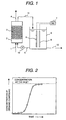
- the treatment apparatus of organic compounds shown in FIG. 1 , provides a supply pipe 1 for supplying the waste water including the organic compounds, an adsorber 2 which is filled with an adsorbent 3 such as activated carbon, a waste water discharging pipe 4, an electrolyzer 6 in which an electrolyte is supplied and a cathode 8 and an anode 9 are provided in the electrolyte, and a DC power supply 7 connected to the cathode 8 and anode 9.
- a supply pipe 1 for supplying the waste water including the organic compounds
- an adsorber 2 which is filled with an adsorbent 3 such as activated carbon
- a waste water discharging pipe 4 an electrolyzer 6 in which an electrolyte is supplied and a cathode 8 and an anode 9 are provided in the electrolyte
- a DC power supply 7 connected to the cathode 8 and anode 9.
- An electrolyte supplying pipe 5 supplies the electrolyte from the electrolyzer 6 to the adsorber 2.
- a pump 10 is connected to the electrolyte supplying pipe 5.
- An electrolyte returning pipe 11 returns the electrolyte from the adsorber 2 to the electrolyzer 6.
- a drain pipe 12 is provided to use an alkaline solution in the electrolyzer 6.
- a piping system for cleaning the adsorbent 3 is not shown in the drawing.
- the organic compound is adsorbed by the adsorbent 3, an alkaline electrolyte and an oxidizing agent, such as hypochlorous acid, that are produced in electrolysis are used to desorb or decompose the organic compounds adsorbed on the adsorbent 3.
- an alkaline electrolyte and an oxidizing agent, such as hypochlorous acid, that are produced in electrolysis are used to desorb or decompose the organic compounds adsorbed on the adsorbent 3.
- the anode 9 and cathode 8 are dipped in the electrolyte in the electrolyzer 6, in which chloride, which becomes a raw material of the oxidizing agent, is added to improve the electric conductivity.
- a DC current is supplied from the DC power supply 7 between the anode 9 and cathode 8.
- the organic compounds are removed from the adsorbent 3 by desorption or decomposition.
- the adsorbent 3 can thus be used again to separate the organic compounds in the waste water by adsorption.
- the organic compounds desorbed in the electrolyte are decomposed by the oxidizing agent produced during electrolysis, eliminating the need for post-treatment of the organic compounds.
- the adsorbent 3 is reproduced with the alkali produced during the electrolysis, so an alkali does not need to be bought.
- the oxidizing agent produced during the electrolysis is used to oxidize and decompose the organic compound, it is also possible to reuse the electrolyte after the decomposition process as alkaline water.
- the electrolyte can also be used as a neutralizing agent for acid.
- the adsorber 2 which has an inner diameter of 40 mm and a length of 200 mm and is made of glass, was internally filled with 50 ml (about 28 g) of activated carbon (Kuraray Coal kw10/32 from Kuraray Co., Ltd., with a particle diameter of 150 to 250 ⁇ m) as the adsorbent 3.
- activated carbon Kuraray Coal kw10/32 from Kuraray Co., Ltd., with a particle diameter of 150 to 250 ⁇ m
- Simulated waste water including 10 g of acetic acid per liter was supplied from the bottom of the adsorber 2 through the supply pipe 1 toward the top at a space velocity (SV) of 19 h -1 so as to have the adsorbent 3 adsorb the acetic acid included in the waste water at room temperature.
- SV space velocity
- the concentration of acetic acid was measured at the exit of the adsorber 2. Almost no acetic acid was detected at an early time of the supply, indicating that the acetic acid was adsorbed by the adsorbent 3.
- the concentration of acetic acid began to rise.
- the concentration of acetic acid became almost the same as the concentration at the inlet. This means that adsorption reached a saturated state.
- the integrated concentrations of acetic acid and the integrated amount of simulated waste water supplied were obtained to obtain the amount of acetic acid adsorbed, which was 70 mg per gram of adsorbent.
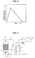
- FIG. 2 schematically shows, in the above situation, changes in the concentration of the organic compound in the waste water at the exit of the adsorber 2. Water was discharged from the adsorber 2 through a discharge pipe 4 in this state.
- the anode 9 and cathode 8 are provided in the electrolyzer 6, which has a volume of 200 ml and is made of glass.
- Sodium chloride (NaCl) was dissolved in purified water to prepare an electrolyte with an NaCl concentration of 1.6 wt%, and the prepared electrolyte was supplied to the electrolyzer 6.
- Electrolysis was then carried out at a current density of 125 mA/cm 2 . While electrolysis was in progress, the electrolyte was supplied to the adsorber 2 at a rate of 16 ml/min. The temperature of the electrolyte at that time was about 30°C.
- the electrolyte discharged from the adsorber 2 was circulated through an electrolyte supply pipe 5 and an electrolyte return pipe 11 disposed between the adsorber 2 and electrolyzer 6, so as to return the electrolyte to the electrolyzer 6.
- the initial pH of the electrolyte was 6.1. While the electrolysis proceeded, the pH shifted to alkalinity and the acetic acid concentration was raised.
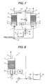
- FIG. 3 schematically shows, in the above situation, changes in the concentration of the organic compounds when the electrolyte was circulated.
- the same test was carried out by using a treatment apparatus of organic compounds, which has the same structure as the above treatment apparatus of organic compounds shown in FIG. 1 ; however, zeolite (H-ZSM-5 with a particle diameter of 1.5 mm, a length of 10 to 20 mm, and three SiO 2 /Al 2 O 3 ratios of 40, 90, and 190) was used as the adsorbent 3, instead of the activated carbon.
- the volume of the adsorbent 3 was 50 ml and the weight was 30 g.
- An electrode formed by coating a titanium substrate with ruthenium oxide and iridium oxide was used as the anode 9 disposed in the electrolyzer 6 in the treatment apparatus of organic compounds, shown in FIG. 1 .
- the cathode 8 was the same as in the treatment apparatus of organic compound, shown in FIG. 1 .
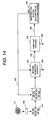
- FIG. 4 shows a treatment apparatus of organic compounds included in waste water useful for understanding the method of the present invention.
- the same reference numerals as in the structure of the treatment apparatus of organic compounds, shown in FIG. 1 indicate identical components, so their detailed explanation will be omitted.
- a chemicals vessel 13 with a volume of, for example, 50 ml was added to the treatment apparatus of organic compounds, shown in FIG. 1 , so that a chemical agent consumed in the electrolyzer 6 can be replenished.
- FIG. 5 illustrates how test was carried out using a treatment apparatus of organic compounds included in waste water useful for understanding the method of the present invention.
- Potassium chloride (KCl) was used, instead of sodium chloride, as the chemical agent in the chemicals vessel 13.
- a 20 wt% KCl solution was supplied in the chemicals vessel 13.
- the electrolyzer 6 was supplied only with water.
- the potassium chloride was supplied from the chemicals vessel 13 to the electrolyzer 6 before electrolysis so that its concentration became 1.0 wt%.
- the resulting solution was stirred with a stirrer (not shown) so that it became uniform, after which a current was supplied between the anode 9 and cathode 8. As a result, it was confirmed that the adsorbed acetic acid was removed, oxidized, and decomposed.
- FIG. 5 When components of the treatment apparatus of organic compounds, shown in FIG. 5 , have the same reference numerals as in the structure of the treatment apparatus of organic compounds, shown in FIG. 4 , these components are identical, so their detailed explanation will be omitted.
- a heat exchanger 15 was added to the electrolyte supplying pipe 5, which is the circulating line from the electrolyzer 6 to the adsorber 2, in the apparatus of FIG. 4 .
- a raw water vessel 16 to reserve the waste water is provided and the waste water in the raw water vessel 16 is supplied to the adsorber 2 through a pipe by a pump 17 provided in the pipe 1.
- the apparatus of Fig. 5 is configured such that, when the electrolyte in the electrolyzer 6 is at a low temperature, the temperature can be raised by using the heat exchanger 15 to heat the electrolyte so as to promote the desorption of the organic compounds; when the temperature of the electrolyte is too high, the electrolyte can be cooled by the heat exchanger 15, enabling the treatment apparatus to be efficiently operated.
- FIG. 6 shows a treatment apparatus of organic compounds included in waste water in an embodiment of the present invention.
- an experiment was carried out in the same way as with the treatment apparatus of organic compounds in waste water, shown in FIG. 4 , except that the electrolyte was raised up to 60°C; it was confirmed that the adsorbed acetic acid was removed, oxidized, and decomposed.
- the electrolyzer 6 is disposed within the adsorber 2 as another treatment method of organic compounds in waste water; specifically, the anode 9 and cathode 8 are disposed at the bottom of the adsorber 2 (supply side of waste water) so that they are orthogonal to the direction in which the waste water flows, and after electrolyte is supplied to the adsorber 2, a circulating pump 18 is started to circulate the electrolyte from the bottom of the adsorber 2 to the top.
- the organic compounds included in the waste water can be reduced to less than a relevant discharge criterion, as in the other examples described above.
- the anode 9 and cathode 8 were internally disposed at the bottom of the adsorber 2, which has an inner diameter of 40 mm and a length of 200 mm and is made of glass.
- the anode 9 and cathode 8 were both circular meshed electrodes with a diameter of 30 mm and a thickness of 1 mm, which were formed by coating a titanium substrate with platinum, the distance between the anode 9 and cathode 8 being 5 mm.
- 50 ml (about 28 g) of activated carbon was filled as the adsorbent 3 above the anode 9 and cathode 8.
- Simulated waste water including 10 g of acetic acid per litter was supplied from the bottom of the adsorber 2 toward the top at a space velocity of 19 h -1 so as to have the adsorbent 3 adsorb the acetic acid included in the waste water.
- the concentration of acetic acid was measured at the exit of the adsorber 2; almost no acetic acid was detected at an early time of the supply, indicating that the acetic acid was adsorbed by the adsorbent 3.
- the integrated concentrations of acetic acid and the integrated amount of simulated waste water supplied were obtained to obtain the amount of acetic acid adsorbed, which was 70 mg per gram of adsorbent.
- the supply of the simulated waste water was stopped and the waste water in the adsorber 2 was discharged through a pipe (not shown).
- the electrolyte with a NaCl concentration of 1.6 wt% stored in the chemicals vessel 13 was then supplied to the adsorber 2.
- the circulating pump 18 was started so that the electrolyte was circulated at a flow rate of 16 ml/min.
- a current with a current density of 250 mA/cm 2 (apparent area) was then supplied between the anode 9 and cathode 8 to cause electrolysis.
- the electrolyte shifted to alkalinity and the acetic acid concentration increased.
- the acetic acid concentration then began to drop and fell to 100 mg/liter or less 120 minutes later.
- the pH at that time was 13.
- the electrolyte was then discharged and the simulated waste water including 10 g of acetic acid per liter was supplied to the adsorber 2 again and adsorption of acetic acid was checked. A result indicated that acetic acid was adsorbed again.
- FIG. 7 shows a treatment apparatus of organic compound included in waste water in a further embodiment of the present invention.
- the same reference numerals as in the structure of the embodiment shown in FIG. 6 indicate identical or equivalent components, so their detailed explanation will be omitted.
- the treatment apparatus of organic compound in waste water in the embodiment shown in FIG. 6 was duplicated (systems A and B were provided side by side). While the adsorbent filled in the adsorber in one system is adsorbing organic compounds from the waste water, organic compounds adsorbed by the adsorbent in the adsorber in the other system is desorbed, oxidized, and decomposed by electrolyte, making it possible to continuously treat the waste water.
- the conditions in the embodiment shown in FIG. 7 were the same as the conditions for the treatment apparatus of organic compounds in the embodiment shown in FIG. 6 .
- a valve 19 for making a switchover of waste water supply was operated to switch over the flow of the waste water to the adsorber 2 in system B to have the adsorbent 3 filled in the adsorber adsorb acetic acid, after which the valve 19 was reversely operated to switch over the flow of the waste water back to the adsorber 2 in system A.
- treatment of the waste water is carried out continuously; while the adsorbent 3 in one adsorber 2 is reproduced, the waste water is supplied to another adsorber 2 and treated.
- the treatment begins by operating the valve 19 to supply the waste water to one adsorber 2 to have the one adsorbent 3 filled in the adsorber 2 adsorb the organic compounds.
- the concentration of the organic compound is measured at the exit of the one adsorber 2 by using an organic compound concentration meter (not shown), the concentration is nearly 0 at an early time; as the amount of adsorbent increases, the concentration of the organic compound at the exit increases.
- the concentration at the exit of the one adsorber 2 reaches a prescribed concentration, which is determined according to a relevant discharge criterion and recycling criterion, when the valve 19 is reversely operated, the destination to which to supply the waste water is switched over to the other adsorber 2; the adsorption of the organic compounds in the waste water is continued by the adsorbent 3 filled in the other adsorber 2.
- a reproduction process is carried out for the one adsorber 2 including the adsorbent 3 by which the organic compound in the waste water has been adsorbed first.
- the electrolyte in the electrolyzer 6 as shown in FIG. 1 is supplied to the adsorbent 3 filled in the adsorber 2 by circulating the electrolyte.
- the state of the reproduction process can be known by measuring the concentration of the organic compounds in the electrolyte.
- the concentration of the organic compound in the electrolyte increases tentatively, after which the organic compound is oxidized and its concentration starts to decrease.
- the reproduction of the adsorbent 3 in the adsorber 2 is completed at a point in time when the concentration of the organic compounds sufficiently decreases, and the electrolyte is stopped from circulating.
- the adsorber 2 is filled with the electrolyte, which is alkaline, at that time, so the alkaline solution is discharged and the filled adsorbent 3 is washed, as necessary.
- the adsorbent 3 is washed with acid or water. Since the organic compound has been removed with an alkaline solution, it is preferable to first wash the adsorbent 3 with acid and then wash it with water. The reproduced adsorbent 3 can thereby adsorb more organic compound.
- TOC total organic carbon
- COD chemical oxygen demand
- adsorbance indirect methods such as electrical conductivity, pH, and other physical quantities may be used instead. If variations in the organic compound concentration are small, it is also possible to operate the apparatus using the amount of waste water that has passed through the adsorbent 3.
- FIG. 8 shows a treatment apparatus of organic compounds included in waste water in a further embodiment of the present invention.
- the same reference numerals as in the structure of the embodiment shown in FIG. 6 indicate identical or equivalent components, so their detailed explanation will be omitted.
- the anode 9 and cathode 8 which are disposed inside the adsorber 2 and at its lower part, are oriented parallel to the direction in which the waste water flows.
- FIG. 9 shows a treatment system of organic compounds included in waste water useful for understanding the method of the present invention.
- the same reference numerals as in the structure of the treatment apparatus of organic compound included in waste, shown in FIG. 1 indicate identical or equivalent components, so their detailed explanation will be omitted.
- the adsorber 2 and electrolyzer 6 are disposed downstream of an oil-water separator.
- the oil-water separator in the apparatus shown in FIG. 9 comprises a coagulant vessel 56, a rotating drum 63, and a separation unit 59; in the coagulant vessel 56, a coagulant 55 and magnetic particles 54 are added from a chemicals feed unit 53 to treated raw water 51 so as to form an oil content into a flock; the rotating drum 63 provides a magnetic field generator 64 that magnetically separates the formed flock including the magnetic particle 54; the separation unit 59 provides a rotating membrane filter 60; organic compounds having large solubility to water, such as organic acids, remains in waste water that passes through the rotating membrane filter 60 and is discharged.
- the organic compounds in this waste water are separated by being adsorbed by the adsorbent 3 in the adsorber 2 disposed downstream of the water-oil separator, and the adsorbent 3 in which the organic compounds are adsorbed is reproduced by using an electrolyte in the electrolyzer 6.
- the coagulant 55 is preferably salt of iron or aluminum, such as ferric sulfate, ferrous chloride, poly aluminum chloride, or the like.
- a suitable magnetic particles are ferromagnetic material, for example, magnetite (Fe 3 O 4 ) and y hematite (Fe 2 O 3 ).
- Oil emulsion particles, solid compound suspended in water, added magnetic particles, and the like are coagulated by the coagulant 55 in the coagulant vessel 56, forming many flocks.
- a pH adjustment 57 such as sodium hydrate, the power of coagulation can be increased.
- Supply of the pH adjustment 57 can be adjusted by using, for example, a pH detector 67 disposed in the coagulant vessel 56 and a valve 68 that controls the amount of supply of the pH adjustment 57 according to a detection signal from the pH detector 67.
- auxiliary coagulant 58 such as anion macromolecular polymer
- the separation unit 59 provides a rotating membrane filter 60 by which the water including many flocks are filtered out; resulting filtered water 61 (referred to below as intermediate water) can be flowed from the rotating membrane filter 60.
- preferable mesh sizes of the rotating membrane filter 60 are 10 to 50 ⁇ m.
- Flocks which include the magnetic particle 54 and are accumulated on the surface of the rotating membrane filter 60, are removed by water jetted from a washing unit 62 disposed in the rotating membrane filter 60, and drop near a rotating drum 63.
- the rotating drum 63 internally provides a magnetic field generator 64 that uses a permanent magnet, superconducting bulk magnet, or electromagnet; the flocks including the magnetic particles 54 are attracted by a magnetic force of the magnetic field generator 64, removed by a sludge recovery plate 65 along the surface of the rotating drum 63, and collected and stored in a sludge vessel 66.
- the sludge recovery plate 65 removes the flocks in the atmosphere rather than in water, moisture drops downward to some extent, resulting in oil sludge with a low percentage of moisture content.
- the sludge can be burnt by adding little or no new fuel.
- Many flocks float in the water because they mainly include oil and thereby have a low specific gravity.
- some flocks may have a high specific gravity depending on the effect by solid substances in the water and the amount of coagulant, and thus may settle in the water. In this case, it is difficult to separate the sludge from the water with high efficiency by utilizing a difference in specific gravity.
- a magnetic force enables highly efficient removal.
- the oil content and suspended substances included in the intermediate water 61 obtained in the separation unit 59 were substantially reduced, very fine micro organic particles and ionized substances originally included in the raw water 51, which are so-called soluble COD components, were included in the intermediate water 61 by a chemical oxygen demand (CODMn) value of about 350 mg/liter.
- CODMn chemical oxygen demand
- the intermediate water 61 was supplied to the adsorber 2 and treated in the same way as in the first example. In this case, the concentration of organic compounds was evaluated with CODMn. The result was the same as in the first example. Since almost all oil contents and suspended substances are removed in advance with coagulation and separation, there is no risk that the surface of the adsorbent 3 is deteriorated.
- waste water that includes organic acids such as formic acid, acetic acid, propionic acid, butyric acid, or valeric acid as the main organic compounds to be treated, and also includes other organic compound, such as lactic acid, glycol, succinic acid, and methanol.
- organic acids such as formic acid, acetic acid, propionic acid, butyric acid, or valeric acid
- other organic compound such as lactic acid, glycol, succinic acid, and methanol.
- Activated carbon (referred to as coal activated carbon or coconut shell activated carbon depending on the raw material), which is a hydrophobic adsorbent, can be used as the adsorbent 3. Many types of activated carbons having different pore distributions and different hydrophobic properties are available. Activated carbon suitable to the type of organic compounds to be treated should be selectively used. Activated carbon also differs in shape and size; for example, it may be granular or spherical. Activated carbon suitable to the process should be selectively used.
- Zeolite can also be used as an adsorbent other than activated carbon.
- Zeolite is classified as natural zeolite, synthesized zeolite, or artificial zeolite according to the manufacturing method and raw material.
- Many types of zeolites having different structures and different SiO 2 /Al 2 O 3 ratios are known. They can also be classified into the Na type, H type, and the like according to the type of the ion in the skeleton.
- Zeolite is classified as ZSM-5, mordenite, L type, ferrierite, or Y type and the like according to the structure.
- the pore diameter ranges from 0.4 to 1.0 nm, depending on the zeolite type. An optimum material should be selected according to the size of the molecule to be treated.
- the hydrophobic property changes depending on the SiO 2 /Al 2 O 3 ratio; it is said that as the SiO 2 /Al 2 O 3 ratio increases, the hydrophobic property is enhanced. Accordingly, when water-soluble organic compound such as organic acids are adsorbed, zeolite having a large SiO 2 /Al 2 O 3 ratio should be used.
- the adsorbent 3 can be formed in granular, spherical, or columnar shape and filled in the adsorber 2.
- the adsorbent 3 can be molded in honeycomb shape or can be formed by coating a honeycomb substrate with an adhesive.
- a reaction indicated by formula (1) or reactions indicated by formulas (2) and (3) proceed at the anode 9, as described above.
- the pH is assumed to be 3 or more. How much hypochlorous acid, which is an oxidizing agent, is produced varies depending on which of formula (2) or formula (3) is dominant. If the reaction indicated by formula (2) mainly proceeds, hypochlorous acid is mainly produced, and the pH of the electrolyte shifts to alkalinity. This result is preferable for the process.
- platinum, ruthenium, iridium, palladium, or rhodium can be used alone or in combination to form the anode 9, or its alloy can also be used.
- a layer of platinum, ruthenium, iridium, palladium, or rhodium alone or in combination or its alloy can be formed on a substrate made of, for example, titanium.
- a diamond electrode for which an overvoltage to produce oxygen is high, is used, hypochlorous acid is produced efficiently.
- the cathode 8 is enough if it produces hydrogen efficiently and is a stable material.
- the cathode 8 may be made of platinum or iridium. Within a range from neutrality to alkalinity, the cathode 8 may be made of iron or nickel.
- An electrode coated on a substrate can also be used.
- the anode 9 and cathode 8 each may be a plate-like or mesh-like electrode.
- a diaphragm or ion exchange membrane may be provided between the anode 9 and cathode 8.
- the electrolyte in the cathode chamber is used for desorption and the electrolyte in the anode chamber is used for oxidization and decomposition, so as to reproduce the adsorbent.
- the electrolysers are stacked, a unipolar system or a bipolar system is applicable.
- the electrolyte needs to include chloride because hypochlorous acid produced from electrolysis is used as the main oxidizing agent.
- the electrolyte also has to fulfill the role of increasing the electric conductivity to reduce the solution resistance. Therefore, sodium chloride or potassium chloride is added.
- the amount of addition is preferably 0.5 to 3 wt% and more preferably 1 to 2 wt%. When water including chloride is used, the amount of addition may be reduced or the need to add chloride may be eliminated.
- Oil sand is dug to produce bitumen.
- Oil sand is a mixture of sand, clay, and bitumen, which is black, clay, asphalt-like hydrocarbon.
- Bitumen is mainly produced by surface mining at present.
- a bitumen collecting system based on surface mining will be described first as a comparative example, with reference to FIG. 10 .
- mined oil sand 101 is milled by a mill 102 and then transferred to a bitumen extracting process 104 by using hot water 103.
- the hot water 103 is also used to extract bitumen 105 in the bitumen extracting process 104.
- the hot water 103 used to extract the bitumen 105 becomes waste water 106.
- the waste water 106 includes suspended solids (SS), which are materials suspended in water, remaining oil, and COD components.
- SS suspended solids
- Supernatant fluid 111 in the water stored in the water reservoir 110 is pumped and sent to a boiler 120, in which the supernatant fluid 111 is heated and used as the hot water 103.
- the COD components do not settle and are left in the supernatant fluid 111, so river water 112 is used to lower the concentration of the COD components included in water to be supplied to the boiler 120.
- the method in the comparative example is significantly problematic in that an environment is destructed due to an enlarged artificial water reservoir and a river from which water is taken is exhausted.
- a bitumen collecting system in a comparative example of the present invention will be described with reference to FIG. 11 .
- bitumen collecting system shown in FIG. 11 , in the eighth embodiment collects bitumen by surface mining.
- bitumen collecting system of Fig. 11 the same reference numerals as in the structure of the bitumen collecting system in the comparative example shown in FIG. 10 indicate identical or equivalent components, so their detailed explanation will be omitted.
- the supernatant fluid 111 in the water reservoir 110 is supplied to a treatment apparatus 130 of organic compounds shown in FIG. 1 , and water produced by the treatment apparatus 130 is delivered to a boiler 120.
- the treatment apparatus 130 of organic compounds is located downstream of the water reservoir 110, the COD components in the supernatant fluid 111 in the water reservoir 110 can be decomposed and removed. Accordingly, it is possible to stop or reduce the supply of the river water 112, reducing a load to the environment.
- a bitumen collecting system in a comparative example of the present invention will be described with reference to FIG. 12 .
- the bitumen collecting system shown in FIG. 12 , is identical to the bitumen collecting system, shown in FIG. 11 , except that the water reservoir 110 is not used.
- the purifying process 108 that can treat the SS in the waste water 106 and the remaining oil at a high level is combined, so the waste water 109 can be supplied directly from the purifying process 108 to the treatment apparatus 130 of organic compounds, without the water reservoir 110 being provided.
- Water produced by the treatment apparatus 130 is then supplied to the boiler 120. Since the water reservoir 110 is eliminated, environment destruction can be suppressed.
- a bitumen collecting system in a comparative example of the present invention will be described with reference to FIG. 13 .
- the bitumen collecting system shown in FIG. 13 , is identical to the bitumen collecting system, shown in FIG. 11 , except that the boiler 120 is not used.
- the treatment apparatus of organic compound shown in FIG. 1 includes an adsorber 2 filled with an adsorbent 3, the waste water including COD components can also be decomposed just by passing the waste water through the electrolyzer 6, without passing the waste water through the adsorber 2.
- the supernatant fluid 111 passes through the electrolyzer 6 in an electrolysis system (Decompose of COD components) 140 Decompose of COD components downstream of the water reservoir 110, enabling the boiler 120 to be eliminated.
- an electrolysis system Decompose of COD components
- the supernatant fluid 111 in the water reservoir 110 is supplied to the electrolysis system 140 without being passed through the adsorber 2 so as to directly perform electrolysis for the supernatant fluid 111 and decompose the COD components.
- the treatment water which is heated by the electrolysis system 140, is then supplied as the hot water 103.
- a cost involved in hot water production by the boiler 120 can thereby be cut.
- the bitumen collecting system in this embodiment achieves both waste water treatment and reduction in energy cost expended for hot water production.
- a bitumen collecting system in a comparative example of the present invention will be described with reference to FIG. 14 .
- the bitumen collecting system shown in FIG. 14 , is identical to the bitumen collecting system, shown in FIG. 11 , except that the boiler 120 is not used.
- the purifying process 108 that can treat the SS in the waste water 106 and the remaining oil at a high level is combined to eliminate the need to use the water reservoir 110, as with the bitumen collecting system shown in FIG. 12 .
- the waste water 109 including COD components from the purifying process 108 for purifying SS and remaining oil can also be decomposed just by passing the waste water through the electrolyzer 6, without passing the waste water through the adsorber 2, so the waste water is supplied to the electrolyzer 6 in the electrolysis system 140 so as to directly perform electrolysis and decompose the COD components.
- the treatment water heated by the electrolysis system 140 is supplied as hot water.
- the bitumen collecting system which can cut the cost in hot water production by the boiler 120, is a treatment system that achieves both waste water treatment and reduction in energy cost expended for hot water production.
- the waste water can be directly supplied without having to provide the water reservoir 110, so the water reservoir 110, which is artificial, can be eliminated and thus environment destruction can be suppressed.
- a biological treatment method is also available as the waste water treatment method.
- oil sand areas where the temperature is -40°C in winter, in Canada, however, an effect by activities of living beings is reduced and efficient treatment cannot be expected.
- the above bitumen collecting systems can maintain their performance without being affected by climatic conditions.
- SAGD steam assisted gravity drainage
- FIG. 15 shows a bitumen collecting system, which is based on the SAGD method, in a second comparative example.
- two horizontal wells 151 and 152 are dipped in an oil sand layer 155.
- Steam 153 is supplied under pressure from the upper well 151 to melt bitumen 161.
- the molten bitumen 161 is collected through the lower horizontal well 152.
- the collected bitumen 161 includes waste water 163 and gas 162, which are separated by a separating unit 160.
- the waste water 163 is purified by a purifier 170 and recycled.
- the amount of water used is three times as much as the amount of bitumen.
- the use of a large amount of water results in environment destruction, exhaustion of the river from which to draw water, and other environmental loads.
- more COD components in the waste water are condensed. Since steam is used in the SAGD method, a high concentration of COD components in the waste water increases damage to equipment.
- FIG. 16 shows the bitumen collecting system, based on the SAGD method.
- the same reference numerals as in the structure of the bitumen collecting system in the comparative example shown in FIG. 15 indicate identical or equivalent components, so their detailed explanation will be omitted.
- the treated water resulting from the purification by a purifying unit 170 in the bitumen collecting system, shown in FIG. 15 , in the comparative example, is treated by the treatment apparatus 130 of organic compounds shown in FIG. 1 ; the treated water produced by the treatment apparatus 130 is supplied to a steam generator 150.
- a bitumen collecting system in a comparative example of the present invention will be described with reference to FIG. 17 .
- the treated water produced by the purifying unit 170 is passed through an electrolysis system 140 having only the electrolyzer 6, without using the adsorber 2, used to decompose organic compounds instead of the treatment apparatus 130 shown in FIG. 16 .
- the treated water is heated during electrolysis in the electrolysis system 140 and supplied to the steam generator 150.
- bitumen collecting systems using the treatment apparatus of organic compounds shown in FIG. 1 have been described, a bitumen collecting system using another treatment apparatus of organic compounds in other embodiments may be used.
- the present invention is applicable to water treatment in which organic compounds included in waste water or discharged water is separated, oxidized, and decomposed to reduce COD and TOC to less than relevant discharge criteria. It is also possible to recycle the waste water.
Landscapes
- Chemical & Material Sciences (AREA)
- Organic Chemistry (AREA)
- Chemical Kinetics & Catalysis (AREA)
- Analytical Chemistry (AREA)
- Engineering & Computer Science (AREA)
- Life Sciences & Earth Sciences (AREA)
- Environmental & Geological Engineering (AREA)
- Water Supply & Treatment (AREA)
- Hydrology & Water Resources (AREA)
- Inorganic Chemistry (AREA)
- Materials Engineering (AREA)
- Toxicology (AREA)
- Electrochemistry (AREA)
- General Chemical & Material Sciences (AREA)
- General Health & Medical Sciences (AREA)
- Physics & Mathematics (AREA)
- Health & Medical Sciences (AREA)
- Electromagnetism (AREA)
- Biodiversity & Conservation Biology (AREA)
- Microbiology (AREA)
- Water Treatment By Electricity Or Magnetism (AREA)
- Water Treatment By Sorption (AREA)
- Treatment Of Water By Oxidation Or Reduction (AREA)
- Separation Of Suspended Particles By Flocculating Agents (AREA)
- Filtration Of Liquid (AREA)
- Solid-Sorbent Or Filter-Aiding Compositions (AREA)
- Production Of Liquid Hydrocarbon Mixture For Refining Petroleum (AREA)
Abstract
Description
- The present invention relates to a treatment method of organic compounds so as to oxidize and decompose water-soluble organic compounds, such as organic acids included in waste water, a treatment apparatus of the organic compounds, a treatment system of the organic compounds, and a system for collecting bitumen.
- In an exemplary method of treatment of organic compounds in waste water, activated carbon is dipped in the waste water to remove the organic compounds by adsorption. In another method, the organic compounds are removed by flowing the waste water through an adsorber filled with an adsorbent.
- In these methods, when the adsorbent reaches its saturation state, no more organic compounds can be adsorbed, in which case the adsorbent has to be replaced, it has to be removed and heated for reproduction, or a new adsorbent has to be added. In the case of replacement, the used activated carbon, which is an adsorbent, has to be handled as a waste material. When heating is performed for reproduction, adsorbed organic compounds are desorbed and thereby treatment of it is involved. Part of the activated carbon is oxidized and consumed during the heating for reproduction.
- Another method is also known, in which the organic compounds in the waste water are oxidized and decomposed by activated oxygen generated by electrolysis. In an example of this method, waste liquid in a waste liquid storage tank is circulated between the waste liquid storage tank and an electrolyzer, and electrolysis is carried out in the electrolyzer so as to generate activated oxygen in the circulating waste liquid; the organic compounds are oxidized and decomposed by an oxidization and decomposition process by the generated activated oxygen (see Patent Document 1). In the
Patent Document 1, the use of an adsorbent is not described. - In a method in which the organic compounds are adsorbed by activated carbon and undergoes electrolysis, liquid resulting from a secondary treatment of human waste is oxidized by ozone and then passed through an electrolysis apparatus in which granular activated carbon is filled between a cathode and an anode, and a current is supplied between the electrodes so that the organic compounds are occluded and adsorbed for electrolytic oxidation (see Patent Document 2). In the method described in the
Patent Document 2, the granular adsorbent is also used as a plurality of electrodes, so the adsorbent must be electrically conductive, limiting the adsorbent to activated carbon. Since the activated carbon works as electrodes, the activated carbon used as the anode is oxidized and thus gradually consumed. - Patent Document 1: Japanese Patent Application Laid-open Publication No.
Hei 8(1996)-192162 - Patent Document 2: Japanese Application Patent Laid-open Publication No.
Sho 59(1984)-127691 -
US 2004/0007533 discloses a method of treating waste water with hypochlorous acid containing liquid produced by electrolysis, and corresponds to the preamble ofclaims 1 and 4. - A large amount of oil content is included in water yielded from an oil field, which is brought during drilling in an oil field, and waste water resulting from the retrieval of heavy crude oil from oil sand. When the waste water is discharged to an ocean or a river, the oil content must be removed to or below a relevant discharge criterion.
- Since environmental restrictions have been enforced in recent years, the amount of oil content included in waste water must be reduced to lower levels. When the waste water is recycled, the oil content must be removed because it adheres to pipes and causes other adverse effects.
- A biological process is available as a method of treatment of oil included in waste water. However, the process takes time and thus a large apparatus is required. There are two types of oil included in waste water; one type of oil is oil content, which does not dissolve in water and is present as grease spots, and the other type of oil dissolves in water like organic acids. When a phase separating agent or coagulant is added to the oil content, the oil content can be separated as a flock.
- For oil that dissolves in water, a method by which the oil is adsorbed by an adsorbent such as activated carbon to separate the oil can be used. When the absorption is saturated, however, the adsorbent must be replaced with a new one or heated to desorb organic compounds so as to reproduce the adsorbent. Post-treatment is also needed for the desorbed organic compounds; for example, the organic compounds must be burnt together with a fuel. Activated carbon also has a drawback; when the activated carbon is heated for reproduction, part of it is oxidized and consumed.
- An object of the present invention is to provide a treatment method of organic compounds included in waste water, a treatment apparatus of the organic compounds, a treatment system of the organic compounds, and a bitumen collecting system; when the organic compounds in the waste water is separated, the organic compounds adsorbed in the adsorbent can thereby be effectively desorbed and decomposed, so reproduction of the adsorbent and decomposition of the organic compounds are carried out with ease.
- (1) Thus, in a first aspect, the present invention provides a treatment method of organic compounds according to
claim 1. - (2) In a second aspect, the present invention provides a treatment apparatus of organic compounds according to claim 4.
- (3) The treatment apparatus of organic compounds of the second aspect of the invention may further comprise : a plurality of adsorbers and a selectively supplying means to supply the waste water including the organic compounds to one adsorber in a plurality of adsorbers for adsorbing the organic compounds included in the waste water by the adsorbent filled in the one adsorber and a concentration of the organic compounds are detected at an exit of the one adsorber and when adsorbing performance is lowered, a destination to supply the waste water is switched over to other adsorber in the plurality of adsorbers for adsorbing the organic compounds included in the waste water.
- (4) In the treatment apparatus of organic compounds included in waste water, described in (2) or (3), preferably a main components of the organic compounds are organic acids.
- (5) In the treatment apparatus of organic compounds included in waste water, described in (2) or (3), preferably the adsorbent is activated carbon or zeolite.
- (6) In the treatment apparatus of organic compounds included in waste water, described in (2) or (3), preferably the anode comprises a titanium substrate and a layer including at least one of platinum, ruthenium, iridium, palladium, and rhodium formed on the titanium substrate.
- (7) In the treatment apparatus of organic compounds included in waste water, described in (2) or (3), preferably the electrolyte is sodium chloride or potassium chloride.
- (8) In another possibility, the inventive treatment system of organic compounds included in waste water comprising: a coagulating vessel to add a coagulant and magnetic particles to the waste water including the organic compounds so as to form a flock including the magnetic particles; a separating unit having a magnetic separator to magnetically separate the flock formed in the waste water and a rotating membrane filter for passing the waste water from a mixture of the waste water and flock; and an apparatus according to the second aspect of the invention is disposed downstream in a direction toward the waste water passed through the rotating membrane filter.
- (9) Another possibility is the inventive bitumen collecting system comprising: a mill for milling mined oil sand; a bitumen extracting apparatus for extracting bitumen by supplying hot water to the milled oil sand; a purifying unit for purifying waste water discharged from the bitumen extracting apparatus; an organic compounds treatment apparatus according to the second aspect of the invention for decomposing the organic compounds in the waste water purified by the purifying unit; and a piping system for supplying water resulting from the treatment by the organic compound treatment apparatus to the bitumen extracting apparatus.
- According to the present invention, organic compounds included in waste water may be separated in a short time by using an adsorbent, and an electrolyte in an electrolyzer is circulated to reproduce the adsorbent, so the adsorbent does not need to be moved. Since salt is added to water only during reproduction, the amount of salt used is small and treated water includes little or no salt, thereby enabling the treated water to be discharged or recycled without additional treatment.
-
-
FIG. 1 is a drawing to show a schematic structure of a treatment apparatus for treating organic compounds included in waste water useful for understanding the method of the present invention. -
FIG. 2 is a drawing to show schematically changes in the concentration of the organic compounds at exit of an adsorber of the treatment apparatus in the embodiments of the present invention. -
FIG. 3 is a drawing to show schematically changes in the concentration of the organic compounds when an electrolyte is circulated during reproduction in the treatment apparatus in the embodiments of the present invention. -
FIG. 4 is a drawing to show a schematic structure of a treatment apparatus for treating organic compounds included in waste water useful for understanding the method of the present invention. -
FIG. 5 is a drawing to show a schematic structure of a treatment apparatus for treating organic compounds included in waste water useful for understanding the method of the present invention. -
FIG. 6 is a drawing to show a schematic structure of a treatment apparatus for treating organic compounds included in waste water in an embodiment of the present invention. -
FIG. 7 is a drawing to show a schematic structure of a treatment apparatus for treating organic compounds included in waste water in a further embodiment of the present invention. -
FIG. 8 is a drawing to show a schematic structure of a treatment apparatus for treating organic compounds included in waste water in a further embodiment of the present invention. -
FIG. 9 is a drawing to show a treatment system for treating organic compounds included in waste water useful for understanding the method of the present invention. -
FIG. 10 is a drawing to show the general structure of a bitumen collecting system, based on surface mining, in a comparative example. -
FIG. 11 is a drawing to show a schematic structure of a bitumen collecting system in a comparative example embodiment of the present invention. -
FIG. 12 is a drawing to show a schematic structure of a bitumen collecting system in a comparative example of the present invention. -
FIG. 13 is a drawing to show a schematic structure of a bitumen collecting system in a comparative example of the present invention. -
FIG. 14 is a drawing to show a schematic structure of a bitumen collecting system in acomparative example of the present invention. -
FIG. 15 is a drawing to show the general structure of a bitumen collecting system, based on the SAGD method, in a comparative example. -
FIG. 16 is a drawing to show a schematic structure of a bitumen collecting system in a comparative example of the present invention. -
FIG. 17 is a drawing to show a schematic structure of a bitumen collecting system in a comparative example of the present invention. - The principle of treatment in the present invention will be described before a mode for carrying out the invention is described.
- In the present invention, while waste water including organic compounds passes through an adsorbent layer filled with adsorbent particles, the organic compounds are adsorbed in the surfaces of the adsorbent particles. The adsorbent particle is, for example, granular, spherical, or columnar, or has a honeycomb structure or the like; there is no restriction on the shape of the adsorbent particle. When the concentration of the organic compounds in the water that has passed through the adsorbent layer is not higher than a relevant discharge criterion, the water can be discharged without additional treatment. When the water satisfies a relevant recycle criterion, the water can be recycled.
- There is a maximum amount of organic compounds that an adsorbent can adsorb (maximum amount of adsorption). When the adsorbent reaches its saturation state, it can no longer adsorb the organic compounds. Accordingly, the adsorbent needs to be replaced with a new one or a reproduction process is required.
- The maximum amount of adsorption depends on the material adsorbed and adsorption conditions; its value varies with the adsorbent.
- In the present invention, an electrolyte produced by electrolysis is used to reproduce the adsorbent. When water in which an electrolyte (sodium chloride, for example) is dissolved is electrolyzed, if the resulting electrolyte is acidic or neutral, it is said that the following reactions occur, that is, chlorine gas, hypochlorous acid, or oxygen is generated from the anode, and hydrogen is generated from the cathode (Kanzaki, Electrochemistry, 73 (No. 11), 969 (2005)).
Anode: 2Cl- + 2e → Cl2 (pH < 3) : : : (1)
Cl- + H2O + 2 e → HClO + H+ (pH > 3) : (2)
H2O → 2H+ + 1/2O2 + 2e : : : (3)
Cathode: 2H+ + 2e → H2: : : (4)
- The ease with which these reactions occur depends on the electrode material. For example, the oxygen overvoltage of platinum is high, so if platinum is used as the anode, production of chlorine or hypochlorous acid rather than oxygen first progresses. Since produced hypochlorous acid is highly oxidative, the organic compounds can be oxidized up to carbon dioxide.
- It was considered that when the hypochlorous acid produced by electrolysis is brought into contact with the adsorbent that adsorbed the organic compounds, the organic compounds can be oxidized and thereby the adsorbent can be reproduced. Part of chlorine produced in formula (1) also dissolves in water, producing hypochlorous acid. In addition to hypochlorous acid, ozone, hydrogen peroxide, or activated oxygen may be produced as an oxidizing agent.
- Accordingly, granular activated carbon was used as the adsorbent to have it adsorb acetic acid, which is one kind of organic acids. An electrolyzer having an anode and cathode made of platinum was prepared, in which electrolysis was carried out by using a sodium chloride solution as the electrolyte. While the electrolysis was in progress, the electrolyte was circulated through the adsorbent in which the acetic acids was adsorbed and changes of the concentration of the acetic acid in the electrolyte with time were observed. The concentration of the acetic acid was raised immediately after the circulation started and then lowered. A possible reason for this is that the rate at which the acetic acid is desorbed from the adsorbent at the contact with the electrolyte is higher than the rate of oxidization and decomposition, so the concentration of the acetic acid in the electrolyte is first raised, and that when the amount of acetic acid desorbed is decreased, the oxidization and decomposition of the acetic acid becomes dominant and the concentration of the acetic acid is lowered.
- A reason why the organic compound is desorbed when the electrolyte is brought into contact with the adsorbent was considered.
- In the electrolysis reactions, no hydrogen ion is produced in formula (1), but one hydrogen ion is produced per two electrons in formula (2). In a reaction on the cathode side according to formula (4), two hydrogen ions disappear per two electrons. That is, when reactions as in formulas (1) and (2) proceed on the anode and a reaction as in formula (4) proceeds on the cathode, hydrogen ions are consumed as a whole and thus the pH shifts toward alkalinity. This means that when nearly neutral water, in which sodium chloride is just dissolved, undergoes electrolysis, an alkaline electrolyte is obtained.
- It could be thought that since the alkaline electrolyte was brought into contact with the adsorbent in which the organic compound was adsorbed, the organic compound was desorbed. Accordingly, it can also be thought that if an anode chamber and cathode chamber are separated by a diaphragm or ion exchange membrane and only the electrolyte in the cathode chamber is used, the alkalinity is increased and the organic compound can be desorbed more effectively. In addition, since the electrolyte is supplied while electrolysis is in progress, a temperature rise is caused due to an electric resistance of the electrolyte. This temperature rise can also enhance the desorbment of the organic compound.
- As described above, in the present invention, an alkaline electrolyte and an oxidizing agent, such as hypochlorous, that are produced during electrolysis are used to desorb or decompose organic compounds adsorbed on an adsorbent. In the electrolysis, an anode and cathode are dipped in an electrolyte in which chloride, which becomes a raw material of the oxidizing agent, is added to improve the electric conductivity. A DC current is supplied between the anode and cathode. Since the electrolyte during electrolysis is brought into contact with the adsorbent, the organic compounds are removed from the adsorbent due to desorption or decomposition. The adsorbent can thus be used again to separate the organic compounds in the waste water by adsorption. The organic compound desorbed in the electrolyte is decomposed by the oxidizing agent produced during electrolysis, eliminating the need for post-treatment of the organic compound.
- According to the present invention, the adsorbent is reproduced with alkali produced during the electrolysis, so alkali does not need to be bought. In addition, since the oxidizing agent produced during the electrolysis is used to oxidize and decompose the organic compounds, it is also possible to reuse the electrolyte after the decomposition process as alkaline water. Of course, the electrolyte can also be used as a neutralizing agent for acid.
- Next, a treatment apparatus of organic compounds included in waste water useful for understanding the method of the above mentioned present invention will be described. The treatment apparatus of organic compounds, shown in
FIG. 1 , provides asupply pipe 1 for supplying the waste water including the organic compounds, anadsorber 2 which is filled with an adsorbent 3 such as activated carbon, a waste water discharging pipe 4, anelectrolyzer 6 in which an electrolyte is supplied and acathode 8 and ananode 9 are provided in the electrolyte, and aDC power supply 7 connected to thecathode 8 andanode 9. - An
electrolyte supplying pipe 5 supplies the electrolyte from theelectrolyzer 6 to theadsorber 2. Apump 10 is connected to theelectrolyte supplying pipe 5. Anelectrolyte returning pipe 11 returns the electrolyte from theadsorber 2 to theelectrolyzer 6. Adrain pipe 12 is provided to use an alkaline solution in theelectrolyzer 6. A piping system for cleaning theadsorbent 3 is not shown in the drawing. - In the above treatment apparatus of organic compounds, the organic compound is adsorbed by the
adsorbent 3, an alkaline electrolyte and an oxidizing agent, such as hypochlorous acid, that are produced in electrolysis are used to desorb or decompose the organic compounds adsorbed on theadsorbent 3. - In the electrolysis, the
anode 9 andcathode 8 are dipped in the electrolyte in theelectrolyzer 6, in which chloride, which becomes a raw material of the oxidizing agent, is added to improve the electric conductivity. A DC current is supplied from theDC power supply 7 between theanode 9 andcathode 8. - Since the electrolyte during electrolysis is brought into contact with the
adsorbent 3, the organic compounds are removed from theadsorbent 3 by desorption or decomposition. Theadsorbent 3 can thus be used again to separate the organic compounds in the waste water by adsorption. - The organic compounds desorbed in the electrolyte are decomposed by the oxidizing agent produced during electrolysis, eliminating the need for post-treatment of the organic compounds. The
adsorbent 3 is reproduced with the alkali produced during the electrolysis, so an alkali does not need to be bought. In addition, since the oxidizing agent produced during the electrolysis is used to oxidize and decompose the organic compound, it is also possible to reuse the electrolyte after the decomposition process as alkaline water. Of course, the electrolyte can also be used as a neutralizing agent for acid. - Test carried out with the treatment apparatus of
Fig. 1 will be described. - In the apparatus shown in
FIG. 1 , theadsorber 2, which has an inner diameter of 40 mm and a length of 200 mm and is made of glass, was internally filled with 50 ml (about 28 g) of activated carbon (Kuraray Coal kw10/32 from Kuraray Co., Ltd., with a particle diameter of 150 to 250 µm) as theadsorbent 3. - Simulated waste water including 10 g of acetic acid per liter was supplied from the bottom of the
adsorber 2 through thesupply pipe 1 toward the top at a space velocity (SV) of 19 h-1 so as to have the adsorbent 3 adsorb the acetic acid included in the waste water at room temperature. - The concentration of acetic acid was measured at the exit of the
adsorber 2. Almost no acetic acid was detected at an early time of the supply, indicating that the acetic acid was adsorbed by theadsorbent 3. When the simulated waste water was continued to be supplied for a while, the concentration of acetic acid began to rise. When about 400 ml of simulated waste water was supplied, the concentration of acetic acid became almost the same as the concentration at the inlet. This means that adsorption reached a saturated state. - The integrated concentrations of acetic acid and the integrated amount of simulated waste water supplied were obtained to obtain the amount of acetic acid adsorbed, which was 70 mg per gram of adsorbent.
-
FIG. 2 schematically shows, in the above situation, changes in the concentration of the organic compound in the waste water at the exit of theadsorber 2. Water was discharged from theadsorber 2 through a discharge pipe 4 in this state. - Next, the
anode 9 andcathode 8 are provided in theelectrolyzer 6, which has a volume of 200 ml and is made of glass. Sodium chloride (NaCl) was dissolved in purified water to prepare an electrolyte with an NaCl concentration of 1.6 wt%, and the prepared electrolyte was supplied to theelectrolyzer 6. The distance between theanode 9 andcathode 8, each of which measured 40 mm x 40 mm with a thickness of 1 mm and was formed by coating a titanium substrate with platinum, was 5 mm. Electrolysis was then carried out at a current density of 125 mA/cm2. While electrolysis was in progress, the electrolyte was supplied to theadsorber 2 at a rate of 16 ml/min. The temperature of the electrolyte at that time was about 30°C. - The electrolyte discharged from the
adsorber 2 was circulated through anelectrolyte supply pipe 5 and anelectrolyte return pipe 11 disposed between theadsorber 2 andelectrolyzer 6, so as to return the electrolyte to theelectrolyzer 6. The initial pH of the electrolyte was 6.1. While the electrolysis proceeded, the pH shifted to alkalinity and the acetic acid concentration was raised. - That is, the acetic acid was removed from the
adsorbent 3. The acetic acid concentration then began to drop and fell to 100 mg/liter or less 120 minutes later. The pH at that time was 13.FIG. 3 schematically shows, in the above situation, changes in the concentration of the organic compounds when the electrolyte was circulated. - Accordingly, it was thought that when the electrolyte was circulated through the adsorbent 3 in which acetic acid was adsorbed, the acetic acid was removed from the
adsorbent 3 and the removed acetic acid was oxidized and decomposed by hypochlorous acid, activated oxygen, or the like produced by the electrolyte. To confirm this, theadsorbent 3 was washed with dilute hydrochloric acid with a concentration of about 1% and then washed with water, after which simulated waste water including acetic acid with a concentration of 10 g/liter was flowed through theadsorber 2 again, and adsorption of acetic acid was checked. A result of the check indicated that acetic acid was adsorbed again. - The same test was carried out by using a treatment apparatus of organic compounds, which has the same structure as the above treatment apparatus of organic compounds shown in
FIG. 1 ; however, zeolite (H-ZSM-5 with a particle diameter of 1.5 mm, a length of 10 to 20 mm, and three SiO2/Al2O3 ratios of 40, 90, and 190) was used as theadsorbent 3, instead of the activated carbon. The volume of theadsorbent 3 was 50 ml and the weight was 30 g. - A test result indicated that the amounts of acetic acid adsorbed by the zeolite with SiO2/Al2O3 ratios of 40, 90, and 190 were respectively 42, 78, and 95 mg/g. It was confirmed as in the first example that the adsorbed acetic acid was removed, oxidized, and decomposed, after which acetic acid was adsorbed again.
- An electrode formed by coating a titanium substrate with ruthenium oxide and iridium oxide was used as the
anode 9 disposed in theelectrolyzer 6 in the treatment apparatus of organic compounds, shown inFIG. 1 . Thecathode 8 was the same as in the treatment apparatus of organic compound, shown inFIG. 1 . - In this example as well, it was confirmed that the adsorbed acetic acid was removed, oxidized, and decomposed.
-
FIG. 4 shows a treatment apparatus of organic compounds included in waste water useful for understanding the method of the present invention. InFIG. 4 , the same reference numerals as in the structure of the treatment apparatus of organic compounds, shown inFIG. 1 , indicate identical components, so their detailed explanation will be omitted. - In the apparatus of
Fig. 4 , achemicals vessel 13 with a volume of, for example, 50 ml was added to the treatment apparatus of organic compounds, shown inFIG. 1 , so that a chemical agent consumed in theelectrolyzer 6 can be replenished. -
FIG. 5 illustrates how test was carried out using a treatment apparatus of organic compounds included in waste water useful for understanding the method of the present invention. Potassium chloride (KCl) was used, instead of sodium chloride, as the chemical agent in thechemicals vessel 13. A 20 wt% KCl solution was supplied in thechemicals vessel 13. - The
electrolyzer 6 was supplied only with water. The potassium chloride was supplied from thechemicals vessel 13 to theelectrolyzer 6 before electrolysis so that its concentration became 1.0 wt%. The resulting solution was stirred with a stirrer (not shown) so that it became uniform, after which a current was supplied between theanode 9 andcathode 8. As a result, it was confirmed that the adsorbed acetic acid was removed, oxidized, and decomposed. - When components of the treatment apparatus of organic compounds, shown in
FIG. 5 , have the same reference numerals as in the structure of the treatment apparatus of organic compounds, shown inFIG. 4 , these components are identical, so their detailed explanation will be omitted. - In the apparatus of
Fig. 5 , to structure an electrolyte circulating line between theelectrolyzer 6 and theadsorber 2, aheat exchanger 15 was added to theelectrolyte supplying pipe 5, which is the circulating line from theelectrolyzer 6 to theadsorber 2, in the apparatus ofFIG. 4 . Araw water vessel 16 to reserve the waste water is provided and the waste water in theraw water vessel 16 is supplied to theadsorber 2 through a pipe by apump 17 provided in thepipe 1. - The apparatus of
Fig. 5 is configured such that, when the electrolyte in theelectrolyzer 6 is at a low temperature, the temperature can be raised by using theheat exchanger 15 to heat the electrolyte so as to promote the desorption of the organic compounds; when the temperature of the electrolyte is too high, the electrolyte can be cooled by theheat exchanger 15, enabling the treatment apparatus to be efficiently operated. -
FIG. 6 shows a treatment apparatus of organic compounds included in waste water in an embodiment of the present invention. In the embodiment shown inFIG. 6 , an experiment was carried out in the same way as with the treatment apparatus of organic compounds in waste water, shown inFIG. 4 , except that the electrolyte was raised up to 60°C; it was confirmed that the adsorbed acetic acid was removed, oxidized, and decomposed. - In the embodiment shown in
FIG. 6 , the same reference numerals as in the structure of the apparatus shown inFIG. 4 indicate identical or equivalent components, so their detailed explanation will be omitted. - In the embodiment of
Fig. 6 , theelectrolyzer 6 is disposed within theadsorber 2 as another treatment method of organic compounds in waste water; specifically, theanode 9 andcathode 8 are disposed at the bottom of the adsorber 2 (supply side of waste water) so that they are orthogonal to the direction in which the waste water flows, and after electrolyte is supplied to theadsorber 2, a circulatingpump 18 is started to circulate the electrolyte from the bottom of theadsorber 2 to the top. - In the embodiment of
Fig. 6 as well, the organic compounds included in the waste water can be reduced to less than a relevant discharge criterion, as in the other examples described above. - In test carried out with the treatment apparatus of organic compounds included in waste water in the embodiment shown in
FIG. 6 , theanode 9 andcathode 8 were internally disposed at the bottom of theadsorber 2, which has an inner diameter of 40 mm and a length of 200 mm and is made of glass. - The
anode 9 andcathode 8 were both circular meshed electrodes with a diameter of 30 mm and a thickness of 1 mm, which were formed by coating a titanium substrate with platinum, the distance between theanode 9 andcathode 8 being 5 mm. 50 ml (about 28 g) of activated carbon (Kuraray Coal kw10/32 from Kuraray Co., Ltd. with a particle diameter of 150 to 250 µm) was filled as theadsorbent 3 above theanode 9 andcathode 8. - Simulated waste water including 10 g of acetic acid per litter was supplied from the bottom of the
adsorber 2 toward the top at a space velocity of 19 h-1 so as to have the adsorbent 3 adsorb the acetic acid included in the waste water. The concentration of acetic acid was measured at the exit of theadsorber 2; almost no acetic acid was detected at an early time of the supply, indicating that the acetic acid was adsorbed by theadsorbent 3. - When the simulated waste water was continued to be supplied for a while, the concentration of acetic acid gradually increased. When about 400 ml of simulated waste water was supplied, the concentration of acetic acid became almost the same as the concentration at the inlet. This means that adsorption reached a saturated state.
- The integrated concentrations of acetic acid and the integrated amount of simulated waste water supplied were obtained to obtain the amount of acetic acid adsorbed, which was 70 mg per gram of adsorbent. In this state, the supply of the simulated waste water was stopped and the waste water in the
adsorber 2 was discharged through a pipe (not shown). - The electrolyte with a NaCl concentration of 1.6 wt% stored in the
chemicals vessel 13 was then supplied to theadsorber 2. After theadsorber 2 was filled with the electrolyte, the circulatingpump 18 was started so that the electrolyte was circulated at a flow rate of 16 ml/min. A current with a current density of 250 mA/cm2 (apparent area) was then supplied between theanode 9 andcathode 8 to cause electrolysis. The electrolyte shifted to alkalinity and the acetic acid concentration increased. The acetic acid concentration then began to drop and fell to 100 mg/liter or less 120 minutes later. The pH at that time was 13. - The electrolyte was then discharged and the simulated waste water including 10 g of acetic acid per liter was supplied to the
adsorber 2 again and adsorption of acetic acid was checked. A result indicated that acetic acid was adsorbed again. -
FIG. 7 shows a treatment apparatus of organic compound included in waste water in a further embodiment of the present invention. In the embodiment shown inFIG. 7 , the same reference numerals as in the structure of the embodiment shown inFIG. 6 indicate identical or equivalent components, so their detailed explanation will be omitted. - In the embodiment of
Fig. 7 , the treatment apparatus of organic compound in waste water in the embodiment shown inFIG. 6 , was duplicated (systems A and B were provided side by side). While the adsorbent filled in the adsorber in one system is adsorbing organic compounds from the waste water, organic compounds adsorbed by the adsorbent in the adsorber in the other system is desorbed, oxidized, and decomposed by electrolyte, making it possible to continuously treat the waste water. - The conditions in the embodiment shown in
FIG. 7 were the same as the conditions for the treatment apparatus of organic compounds in the embodiment shown inFIG. 6 . First, avalve 19 for making a switchover of waste water supply was operated to switch over the flow of the waste water to theadsorber 2 in system B to have the adsorbent 3 filled in the adsorber adsorb acetic acid, after which thevalve 19 was reversely operated to switch over the flow of the waste water back to theadsorber 2 in system A. - While acetic acid was being adsorbed by the
adsorbent 3 filled in theadsorber 2 in system B, the waste water was discharged from theadsorber 2 in system A, andvalves chemicals vessel 13 to theadsorbent 3 filled in theadsorber 2 in system A, after which the circulatingpump 18 was started to circulate the electrolyte. A current was then supplied between theanode 9 andcathode 8. After the current supply was continued for a fixed length of time, the electrolyte was discharged from theadsorber 2 in system B and the supply of the waste water was switched over to theadsorber 2 in system A. - In this embodiment, treatment of the waste water is carried out continuously; while the
adsorbent 3 in oneadsorber 2 is reproduced, the waste water is supplied to anotheradsorber 2 and treated. - A case in which two
adsorbers 2 are provided will be described below. The treatment begins by operating thevalve 19 to supply the waste water to oneadsorber 2 to have the oneadsorbent 3 filled in theadsorber 2 adsorb the organic compounds. - When the concentration of the organic compound is measured at the exit of the one
adsorber 2 by using an organic compound concentration meter (not shown), the concentration is nearly 0 at an early time; as the amount of adsorbent increases, the concentration of the organic compound at the exit increases. - If the concentration at the exit of the one
adsorber 2 reaches a prescribed concentration, which is determined according to a relevant discharge criterion and recycling criterion, when thevalve 19 is reversely operated, the destination to which to supply the waste water is switched over to theother adsorber 2; the adsorption of the organic compounds in the waste water is continued by theadsorbent 3 filled in theother adsorber 2. A reproduction process is carried out for the oneadsorber 2 including theadsorbent 3 by which the organic compound in the waste water has been adsorbed first. - To reproduce the
adsorbent 3 filled in theadsorber 2, the electrolyte in theelectrolyzer 6 as shown inFIG. 1 is supplied to theadsorbent 3 filled in theadsorber 2 by circulating the electrolyte. The state of the reproduction process can be known by measuring the concentration of the organic compounds in the electrolyte. - As described before, when the organic compound is desorbed from the
adsorbent 3, the concentration of the organic compound in the electrolyte increases tentatively, after which the organic compound is oxidized and its concentration starts to decrease. The reproduction of the adsorbent 3 in theadsorber 2 is completed at a point in time when the concentration of the organic compounds sufficiently decreases, and the electrolyte is stopped from circulating. - The
adsorber 2 is filled with the electrolyte, which is alkaline, at that time, so the alkaline solution is discharged and the filledadsorbent 3 is washed, as necessary. - The
adsorbent 3 is washed with acid or water. Since the organic compound has been removed with an alkaline solution, it is preferable to first wash theadsorbent 3 with acid and then wash it with water. The reproducedadsorbent 3 can thereby adsorb more organic compound. - To measure the concentration of the organic compounds, total organic carbon (TOC), chemical oxygen demand (COD), adsorbance, and indirect methods such as electrical conductivity, pH, and other physical quantities may be used instead. If variations in the organic compound concentration are small, it is also possible to operate the apparatus using the amount of waste water that has passed through the
adsorbent 3. -
FIG. 8 shows a treatment apparatus of organic compounds included in waste water in a further embodiment of the present invention. In the embodiment shown inFIG. 8 , the same reference numerals as in the structure of the embodiment shown inFIG. 6 indicate identical or equivalent components, so their detailed explanation will be omitted. - In the embodiment of
Fig. 8 , theanode 9 andcathode 8, which are disposed inside theadsorber 2 and at its lower part, are oriented parallel to the direction in which the waste water flows. - In the embodiment of
Fig.8 , an experiment was performed under the same conditions as in the embodiment shown inFIG. 6 ; results obtained were similar to the results in the embodiment ofFig. 6 . -
FIG. 9 shows a treatment system of organic compounds included in waste water useful for understanding the method of the present invention. In the treatment system of organic compounds, shown inFIG. 9 , the same reference numerals as in the structure of the treatment apparatus of organic compound included in waste, shown inFIG. 1 indicate identical or equivalent components, so their detailed explanation will be omitted. - In the treatment system of organic compound shown in
Fig. 9 , theadsorber 2 andelectrolyzer 6 are disposed downstream of an oil-water separator. - The oil-water separator in the apparatus shown in
FIG. 9 comprises acoagulant vessel 56, arotating drum 63, and aseparation unit 59; in thecoagulant vessel 56, acoagulant 55 andmagnetic particles 54 are added from achemicals feed unit 53 to treatedraw water 51 so as to form an oil content into a flock; therotating drum 63 provides amagnetic field generator 64 that magnetically separates the formed flock including themagnetic particle 54; theseparation unit 59 provides arotating membrane filter 60; organic compounds having large solubility to water, such as organic acids, remains in waste water that passes through therotating membrane filter 60 and is discharged. - The organic compounds in this waste water are separated by being adsorbed by the
adsorbent 3 in theadsorber 2 disposed downstream of the water-oil separator, and theadsorbent 3 in which the organic compounds are adsorbed is reproduced by using an electrolyte in theelectrolyzer 6. - In the apparatus of
Fig. 9 , while treatedraw water 51 including oil (which is yielded from an oil field and referred to as raw water) is flowing in apipe 52 from which the raw water is supplied to thecoagulant vessel 56, themagnetic particles 54 andcoagulant 55 are added from the chemicals feedunit 53 to the raw water. - The
coagulant 55 is preferably salt of iron or aluminum, such as ferric sulfate, ferrous chloride, poly aluminum chloride, or the like. A suitable magnetic particles are ferromagnetic material, for example, magnetite (Fe3O4) and y hematite (Fe2O3). - Oil emulsion particles, solid compound suspended in water, added magnetic particles, and the like are coagulated by the
coagulant 55 in thecoagulant vessel 56, forming many flocks. When the pH is adjusted to a suitable value by apH adjustment 57 such as sodium hydrate, the power of coagulation can be increased. - Supply of the
pH adjustment 57 can be adjusted by using, for example, apH detector 67 disposed in thecoagulant vessel 56 and avalve 68 that controls the amount of supply of thepH adjustment 57 according to a detection signal from thepH detector 67. - When an
auxiliary coagulant 58 such as anion macromolecular polymer is supplied into thecoagulant vessel 56, the flock can be enlarged and consolidated. - The
separation unit 59 provides arotating membrane filter 60 by which the water including many flocks are filtered out; resulting filtered water 61 (referred to below as intermediate water) can be flowed from the rotatingmembrane filter 60. When efficiency of flock removal is considered, preferable mesh sizes of therotating membrane filter 60 are 10 to 50 µm. - Flocks, which include the
magnetic particle 54 and are accumulated on the surface of therotating membrane filter 60, are removed by water jetted from awashing unit 62 disposed in therotating membrane filter 60, and drop near arotating drum 63. Therotating drum 63 internally provides amagnetic field generator 64 that uses a permanent magnet, superconducting bulk magnet, or electromagnet; the flocks including themagnetic particles 54 are attracted by a magnetic force of themagnetic field generator 64, removed by asludge recovery plate 65 along the surface of therotating drum 63, and collected and stored in asludge vessel 66. - Since the
sludge recovery plate 65 removes the flocks in the atmosphere rather than in water, moisture drops downward to some extent, resulting in oil sludge with a low percentage of moisture content. - Accordingly, a cost for disposing of the sludge can be reduced. In some cases, the sludge can be burnt by adding little or no new fuel. Many flocks float in the water because they mainly include oil and thereby have a low specific gravity. However, some flocks may have a high specific gravity depending on the effect by solid substances in the water and the amount of coagulant, and thus may settle in the water. In this case, it is difficult to separate the sludge from the water with high efficiency by utilizing a difference in specific gravity. By contrast, a magnetic force enables highly efficient removal.
- Although an example of separation by using a combination of a rotating membrane filter and a magnetic force has been described, the use of another separation method, such as a chemical clarification method or a coagulation and floatation method, also enables the present invention to provide the same effect.
- Although the oil content and suspended substances included in the
intermediate water 61 obtained in theseparation unit 59 were substantially reduced, very fine micro organic particles and ionized substances originally included in theraw water 51, which are so-called soluble COD components, were included in theintermediate water 61 by a chemical oxygen demand (CODMn) value of about 350 mg/liter. Theintermediate water 61 was supplied to theadsorber 2 and treated in the same way as in the first example. In this case, the concentration of organic compounds was evaluated with CODMn. The result was the same as in the first example. Since almost all oil contents and suspended substances are removed in advance with coagulation and separation, there is no risk that the surface of theadsorbent 3 is deteriorated. - In the examples and embodiments of the present invention described above, it is possible to treat waste water that includes organic acids such as formic acid, acetic acid, propionic acid, butyric acid, or valeric acid as the main organic compounds to be treated, and also includes other organic compound, such as lactic acid, glycol, succinic acid, and methanol.
- Activated carbon (referred to as coal activated carbon or coconut shell activated carbon depending on the raw material), which is a hydrophobic adsorbent, can be used as the
adsorbent 3. Many types of activated carbons having different pore distributions and different hydrophobic properties are available. Activated carbon suitable to the type of organic compounds to be treated should be selectively used. Activated carbon also differs in shape and size; for example, it may be granular or spherical. Activated carbon suitable to the process should be selectively used. - Zeolite can also be used as an adsorbent other than activated carbon. Zeolite is classified as natural zeolite, synthesized zeolite, or artificial zeolite according to the manufacturing method and raw material. Many types of zeolites having different structures and different SiO2/Al2O3 ratios are known. They can also be classified into the Na type, H type, and the like according to the type of the ion in the skeleton. Zeolite is classified as ZSM-5, mordenite, L type, ferrierite, or Y type and the like according to the structure. The pore diameter ranges from 0.4 to 1.0 nm, depending on the zeolite type. An optimum material should be selected according to the size of the molecule to be treated. The hydrophobic property changes depending on the SiO2/Al2O3 ratio; it is said that as the SiO2/Al2O3 ratio increases, the hydrophobic property is enhanced. Accordingly, when water-soluble organic compound such as organic acids are adsorbed, zeolite having a large SiO2/Al2O3 ratio should be used.
- The
adsorbent 3 can be formed in granular, spherical, or columnar shape and filled in theadsorber 2. Alternatively, theadsorbent 3 can be molded in honeycomb shape or can be formed by coating a honeycomb substrate with an adhesive. - As for the electrodes used for electrolysis, a reaction indicated by formula (1) or reactions indicated by formulas (2) and (3) proceed at the
anode 9, as described above. In the description below, the pH is assumed to be 3 or more. How much hypochlorous acid, which is an oxidizing agent, is produced varies depending on which of formula (2) or formula (3) is dominant. If the reaction indicated by formula (2) mainly proceeds, hypochlorous acid is mainly produced, and the pH of the electrolyte shifts to alkalinity. This result is preferable for the process. - Accordingly, in the present invention, platinum, ruthenium, iridium, palladium, or rhodium can be used alone or in combination to form the
anode 9, or its alloy can also be used. Alternatively, a layer of platinum, ruthenium, iridium, palladium, or rhodium alone or in combination or its alloy can be formed on a substrate made of, for example, titanium. When a diamond electrode, for which an overvoltage to produce oxygen is high, is used, hypochlorous acid is produced efficiently. In addition, it is also possible to directly oxidize and decompose the organic acids. - The
cathode 8 is enough if it produces hydrogen efficiently and is a stable material. As with theanode 9, thecathode 8 may be made of platinum or iridium. Within a range from neutrality to alkalinity, thecathode 8 may be made of iron or nickel. An electrode coated on a substrate can also be used. - The
anode 9 andcathode 8 each may be a plate-like or mesh-like electrode. A diaphragm or ion exchange membrane may be provided between theanode 9 andcathode 8. In this case, however, the electrolyte in the cathode chamber is used for desorption and the electrolyte in the anode chamber is used for oxidization and decomposition, so as to reproduce the adsorbent. When the electrolysers are stacked, a unipolar system or a bipolar system is applicable. - The electrolyte needs to include chloride because hypochlorous acid produced from electrolysis is used as the main oxidizing agent. The electrolyte also has to fulfill the role of increasing the electric conductivity to reduce the solution resistance. Therefore, sodium chloride or potassium chloride is added. The amount of addition is preferably 0.5 to 3 wt% and more preferably 1 to 2 wt%. When water including chloride is used, the amount of addition may be reduced or the need to add chloride may be eliminated.
- Next, systems in which the treatment apparatus of organic compounds included in waste water, described with referenceto
Fig. 1 above, is applied to production of bitumen from oil sand will be described with reference toFIGs. 10 to 17 . - In Canada, oil sand is dug to produce bitumen. Oil sand is a mixture of sand, clay, and bitumen, which is black, clay, asphalt-like hydrocarbon. Bitumen is mainly produced by surface mining at present.
- A bitumen collecting system based on surface mining will be described first as a comparative example, with reference to
FIG. 10 . - In the comparative example in
FIG. 10 , minedoil sand 101 is milled by amill 102 and then transferred to abitumen extracting process 104 by usinghot water 103. Thehot water 103 is also used to extractbitumen 105 in thebitumen extracting process 104. - The
hot water 103 used to extract thebitumen 105 becomeswaste water 106. Thewaste water 106 includes suspended solids (SS), which are materials suspended in water, remaining oil, and COD components. - Part of the SS and remaining oil are purified in a
purifying process 108, butwaste water 109 including SS and remainingoil 107, which have not been treated, is transferred to awater reservoir 110. The SS and remainingoil 107 are made to settle in thewater reservoir 110 by taking a time. - Much water is used to collect bitumen.
Supernatant fluid 111 in the water stored in thewater reservoir 110 is pumped and sent to aboiler 120, in which thesupernatant fluid 111 is heated and used as thehot water 103. However, the COD components do not settle and are left in thesupernatant fluid 111, soriver water 112 is used to lower the concentration of the COD components included in water to be supplied to theboiler 120. - Since much water is necessary to collect bitumen as described above, the method in the comparative example is significantly problematic in that an environment is destructed due to an enlarged artificial water reservoir and a river from which water is taken is exhausted.
- A bitumen collecting system in a comparative example of the present invention will be described with reference to
FIG. 11 . - The bitumen collecting system, shown in
FIG. 11 , in the eighth embodiment collects bitumen by surface mining. In the bitumen collecting system ofFig. 11 , the same reference numerals as in the structure of the bitumen collecting system in the comparative example shown inFIG. 10 indicate identical or equivalent components, so their detailed explanation will be omitted. - In the bitumen collecting system, shown in
FIG. 11 , thesupernatant fluid 111 in thewater reservoir 110 is supplied to atreatment apparatus 130 of organic compounds shown inFIG. 1 , and water produced by thetreatment apparatus 130 is delivered to aboiler 120. - Since the
treatment apparatus 130 of organic compounds is located downstream of thewater reservoir 110, the COD components in thesupernatant fluid 111 in thewater reservoir 110 can be decomposed and removed. Accordingly, it is possible to stop or reduce the supply of theriver water 112, reducing a load to the environment. - A bitumen collecting system in a comparative example of the present invention will be described with reference to
FIG. 12 . - The bitumen collecting system, shown in
FIG. 12 , is identical to the bitumen collecting system, shown inFIG. 11 , except that thewater reservoir 110 is not used. - In the bitumen collecting system, shown in
FIG. 12 , thepurifying process 108 that can treat the SS in thewaste water 106 and the remaining oil at a high level is combined, so thewaste water 109 can be supplied directly from thepurifying process 108 to thetreatment apparatus 130 of organic compounds, without thewater reservoir 110 being provided. - Water produced by the
treatment apparatus 130 is then supplied to theboiler 120. Since thewater reservoir 110 is eliminated, environment destruction can be suppressed. - A bitumen collecting system in a comparative example of the present invention will be described with reference to
FIG. 13 . - The bitumen collecting system, shown in
FIG. 13 , is identical to the bitumen collecting system, shown inFIG. 11 , except that theboiler 120 is not used. - In oil sand processing in which much hot water is used, cold water is heated by the
boiler 120 to make hot water used for bitumen production, consuming much energy. - Although the treatment apparatus of organic compound shown in
FIG. 1 includes anadsorber 2 filled with anadsorbent 3, the waste water including COD components can also be decomposed just by passing the waste water through theelectrolyzer 6, without passing the waste water through theadsorber 2. - In the bitumen collecting system, shown in
FIG. 13 , thesupernatant fluid 111 passes through theelectrolyzer 6 in an electrolysis system (Decompose of COD components) 140 Decompose of COD components downstream of thewater reservoir 110, enabling theboiler 120 to be eliminated. - The
supernatant fluid 111 in thewater reservoir 110 is supplied to theelectrolysis system 140 without being passed through theadsorber 2 so as to directly perform electrolysis for thesupernatant fluid 111 and decompose the COD components. - The treatment water, which is heated by the
electrolysis system 140, is then supplied as thehot water 103. A cost involved in hot water production by theboiler 120 can thereby be cut. The bitumen collecting system in this embodiment achieves both waste water treatment and reduction in energy cost expended for hot water production. - A bitumen collecting system in a comparative example of the present invention will be described with reference to
FIG. 14 . - The bitumen collecting system, shown in
FIG. 14 , is identical to the bitumen collecting system, shown inFIG. 11 , except that theboiler 120 is not used. - In the bitumen collecting system, shown in
FIG. 14 , thepurifying process 108 that can treat the SS in thewaste water 106 and the remaining oil at a high level is combined to eliminate the need to use thewater reservoir 110, as with the bitumen collecting system shown inFIG. 12 . - The
waste water 109 including COD components from thepurifying process 108 for purifying SS and remaining oil can also be decomposed just by passing the waste water through theelectrolyzer 6, without passing the waste water through theadsorber 2, so the waste water is supplied to theelectrolyzer 6 in theelectrolysis system 140 so as to directly perform electrolysis and decompose the COD components. The treatment water heated by theelectrolysis system 140 is supplied as hot water. - The bitumen collecting system, which can cut the cost in hot water production by the
boiler 120, is a treatment system that achieves both waste water treatment and reduction in energy cost expended for hot water production. - As with the bitumen collecting system shown in
FIG. 13 , the waste water can be directly supplied without having to provide thewater reservoir 110, so thewater reservoir 110, which is artificial, can be eliminated and thus environment destruction can be suppressed. - A biological treatment method is also available as the waste water treatment method. In oil sand areas, where the temperature is -40°C in winter, in Canada, however, an effect by activities of living beings is reduced and efficient treatment cannot be expected. By contrast, the above bitumen collecting systems can maintain their performance without being affected by climatic conditions.
- In addition to surface mining, the steam assisted gravity drainage (SAGD) method is available as a bitumen production method.
- A comparative example of a bitumen collecting method based on the SAGD method will be described below. In the SAGD method, steam is used to lower the viscosity of bitumen before it is collected.
FIG. 15 shows a bitumen collecting system, which is based on the SAGD method, in a second comparative example. - As shown in
FIG. 15 , twohorizontal wells oil sand layer 155.Steam 153 is supplied under pressure from theupper well 151 to meltbitumen 161. Themolten bitumen 161 is collected through the lowerhorizontal well 152. - The collected
bitumen 161 includeswaste water 163 andgas 162, which are separated by aseparating unit 160. Thewaste water 163 is purified by apurifier 170 and recycled. - When the recycling of the
waste water 163 is incomplete,river water 112 is drawn and used. - To produce one barrel of
bitumen 161, the amount of water used is three times as much as the amount of bitumen. The use of a large amount of water results in environment destruction, exhaustion of the river from which to draw water, and other environmental loads. To reduce the environmental loads, it is preferable to recycle thewaste water 163. However, as the recycle ratio is increased, more COD components in the waste water are condensed. Since steam is used in the SAGD method, a high concentration of COD components in the waste water increases damage to equipment. - A bitumen collecting system, based on the SAGD method, will be described.
FIG. 16 shows the bitumen collecting system, based on the SAGD method. In the bitumen collecting system ofFig. 16 , the same reference numerals as in the structure of the bitumen collecting system in the comparative example shown inFIG. 15 indicate identical or equivalent components, so their detailed explanation will be omitted. - In the bitumen collecting system, shown in
FIG. 16 , the treated water resulting from the purification by apurifying unit 170 in the bitumen collecting system, shown inFIG. 15 , in the comparative example, is treated by thetreatment apparatus 130 of organic compounds shown inFIG. 1 ; the treated water produced by thetreatment apparatus 130 is supplied to asteam generator 150. - When the bitumen collecting system, shown in
FIG. 16 , is used to remove and decompose the COD components in waste water, damage to the equipment can be reduced. - Checking to the equipment can thus be reduced and the availability of the apparatus can also be increased.
- A bitumen collecting system in a comparative example of the present invention will be described with reference to
FIG. 17 . - In the bitumen collecting system, shown in
FIG. 17 , the treated water produced by thepurifying unit 170 is passed through anelectrolysis system 140 having only theelectrolyzer 6, without using theadsorber 2, used to decompose organic compounds instead of thetreatment apparatus 130 shown inFIG. 16 . In this structure, the treated water is heated during electrolysis in theelectrolysis system 140 and supplied to thesteam generator 150. - Since energy cost involved in steam production by the
steam generator 150 can thereby be reduced, both treatment and recycling of waste water and a reduction in production cost can be achieved. - Although, in
Figs. 16 and17 bitumen collecting systems using the treatment apparatus of organic compounds shown inFIG. 1 have been described, a bitumen collecting system using another treatment apparatus of organic compounds in other embodiments may be used. - The present invention is applicable to water treatment in which organic compounds included in waste water or discharged water is separated, oxidized, and decomposed to reduce COD and TOC to less than relevant discharge criteria. It is also possible to recycle the waste water.
Claims (11)
- A treatment method of organic compounds included in waste water, comprising the steps of:supplying waste water to an adsorber (2) filled with an adsorbent (3) therein for adsorbing the organic compounds in the waste water by the adsorbent (3) in the adsorber (2),supplying a current between an anode (9) and a cathode (8) in water including an electrolyte having chloride therein in an electrolyser (6) for electrolysing the water including an electrolyte, and producing an electrolyte, andcirculating the electrolyte that is thus produced in a flow direction through the adsorbent (3) in the absorber (2), thereby contacting the adsorbent (3) with the electrolyte so that the organic compounds adsorbed by the adsorbent (3) are desorbed or decomposed,wherein the anode (9) and the cathode (8) are disposed upstream of the adsorbent (3) in the flow direction, andcharacterized in that the electrolyte that is produced in the electrolyser (6) is supplied to the adsorbent (3) in the adsorber (2) while the electrolysis is in progress, and
the anode (1) and the cathode (8) are disposed inside the adsorber (2). - The treatment method of organic compounds included in waste water according to claim 1, wherein the electrolyte is circulated from the electrolyser (6) to the adsorbent (3), and circulated from the adsorber (2) to the electrolyser (6) to return the electrolyte to the electrolyser (6).
- The treatment method of organic compounds included in waste water according to claim 1 or 2, including
supplying the waste water to one adsorber (2) in a plurality of adsorbers for adsorbing the organic compounds included in the waste water by the adsorbent (3) filled in the one adsorber;
detecting a concentration of the organic compound in the waste water at an exit of the one adsorber and, when adsorbing performance is lowered, switching over a destination to supply the waste water to another adsorber in the plurality of adsorbers for adsorbing the organic compounds included in the waste water by the adsorbent filled in another adsorber and discontinuing waste water supply to the one adsorber (2);
supplying an electrolyte resulting from electrolysis in the electrolyser (6) to the adsorbent (3) in the one adsorber (2) to which the waste water supply is discontinued to desorb or decompose the organic compounds adsorbed in the adsorbent (3) of which adsorbing performance is lowered. - A treatment apparatus of organic compounds included in waste water, the apparatus comprising:an adsorber (2) filled with an adsorbent (3) therein; andan electrolyser (6) having an anode (9) and a cathode (8) therein for electrolysing water including an electrolyte having chloride therein when a current is supplied between the anode (9) and cathode (8); anda circulating pump (18) for circulating the electrolyte from the electrolyser (6) in a flow direction through the adsorbent (3) in the absorber (2) to desorb or decompose the organic compounds adsorbed in the adsorbent (3),wherein the anode (9) and the cathode (8) are disposed upstream of the adsorbent (3) in the flow direction and the apparatus is configured to receive waste water including the organic compounds in the adsorber (2) for adsorbing the organic compounds by the adsorbent (3) filled in the adsorber, andcharacterized in that the electrolyser (6) is disposed inside the adsorber (2).
- A treatment apparatus of organic compounds included in waste water according to claim 4, comprising:a plurality of the adsorbers (2);a selectively supplying means (19) to supply the waste water including the organic compounds to one adsorber in the plurality of adsorbers for adsorbing the organic compounds included in the waste water by the adsorbent (3) filled in the one adsorber; anda detector for detecting a concentration of the organic compounds at an exit of the one adsorber,wherein, when the detector detects that adsorbing performance is lowered, the apparatus is arranged to switch over the selectively supplying means (19) to supply the waste water to another adsorber in the plurality of adsorbers for adsorbing the organic compounds included in the waste water.
- The treatment apparatus of organic compounds included in waste water according to claim 4, wherein a main component of the organic compounds is organic acids.
- The treatment apparatus of organic compounds included in waste water according to claim 4, wherein the adsorbent (3) is activated carbon or zeolite.
- The treatment apparatus of organic compounds included in waste water according to claim 4, wherein the anode (9) comprises a titanium substrate and a layer including at least one of platinum ruthenium, iridium, palladium, and rhodium formed on the titanium substrate.
- The treatment apparatus of organic compounds included in waste water according to claim 4, wherein the electrolyte is sodium chloride or potassium chloride.
- A treatment system of organic compounds included in waste water comprising:a coagulating vessel (56) to add a coagulant (55) and a magnetic particles (54) to the waste water including the organic compounds so as to form a flock including the magnetic particles;a separating unit (59) having a magnetic separator to magnetically separate the flock formed in the waste water and a rotating membrane filter (60) for passing the waste water from a mixture of the waste water and flock; andan organic compound treatment apparatus for the organic compounds in the waste water according to claim 4 is disposed downstream in a direction toward the waste water passed through the rotating membrane filter (60).
- A bitumen collecting system comprising:a mill (102) for milling mined oil sand (101);a bitumen extracting apparatus for extracting bitumen by supplying hot water (103) to the milled oil sand (101);a purifying unit (170) for purifying waste water discharged from the bitumen extracting apparatus;an organic compound treatment apparatus (130) for decomposing the organic compounds in the waste water purified by the purifying unit; anda piping system for supplying water resulting from the treatment by the organic compound treatment apparatus to the bitumen extracting apparatus,wherein, the organic compound treatment apparatus for decomposing the organic compounds in the waste water purified by the purifying unit is an organic compound treatment apparatus for the organic compounds in the waste water according to claim 4.
Priority Applications (1)
| Application Number | Priority Date | Filing Date | Title |
|---|---|---|---|
| EP09008038A EP2113487A3 (en) | 2007-04-09 | 2008-02-22 | An apparatus, a system and a treatment method for organic compounds included in waste water from a bitumen collecting system |
Applications Claiming Priority (1)
| Application Number | Priority Date | Filing Date | Title |
|---|---|---|---|
| JP2007101498 | 2007-04-09 |
Related Child Applications (2)
| Application Number | Title | Priority Date | Filing Date |
|---|---|---|---|
| EP09008038A Division EP2113487A3 (en) | 2007-04-09 | 2008-02-22 | An apparatus, a system and a treatment method for organic compounds included in waste water from a bitumen collecting system |
| EP09008038.3 Division-Into | 2009-06-19 |
Publications (3)
| Publication Number | Publication Date |
|---|---|
| EP1997782A2 EP1997782A2 (en) | 2008-12-03 |
| EP1997782A3 EP1997782A3 (en) | 2009-01-28 |
| EP1997782B1 true EP1997782B1 (en) | 2011-04-27 |
Family
ID=39561917
Family Applications (2)
| Application Number | Title | Priority Date | Filing Date |
|---|---|---|---|
| EP08250622A Not-in-force EP1997782B1 (en) | 2007-04-09 | 2008-02-22 | An apparatus, a system and a treatment method for organic compounds included in waste water |
| EP09008038A Withdrawn EP2113487A3 (en) | 2007-04-09 | 2008-02-22 | An apparatus, a system and a treatment method for organic compounds included in waste water from a bitumen collecting system |
Family Applications After (1)
| Application Number | Title | Priority Date | Filing Date |
|---|---|---|---|
| EP09008038A Withdrawn EP2113487A3 (en) | 2007-04-09 | 2008-02-22 | An apparatus, a system and a treatment method for organic compounds included in waste water from a bitumen collecting system |
Country Status (9)
| Country | Link |
|---|---|
| US (2) | US7722773B2 (en) |
| EP (2) | EP1997782B1 (en) |
| JP (1) | JP5052382B2 (en) |
| KR (1) | KR20080091699A (en) |
| CN (1) | CN101284704A (en) |
| AT (1) | ATE507190T1 (en) |
| AU (1) | AU2008200884B2 (en) |
| CA (1) | CA2621996C (en) |
| DE (1) | DE602008006485D1 (en) |
Cited By (2)
| Publication number | Priority date | Publication date | Assignee | Title |
|---|---|---|---|---|
| US9593032B2 (en) | 2012-11-30 | 2017-03-14 | General Electric Company | Produced water treatment to remove organic compounds |
| EP3643392A1 (en) | 2018-10-26 | 2020-04-29 | Chemion Logistik GmbH | Activated carbon adsorption unit and method for its production |
Families Citing this family (46)
| Publication number | Priority date | Publication date | Assignee | Title |
|---|---|---|---|---|
| DE102007041828A1 (en) * | 2007-09-03 | 2009-03-05 | Siemens Ag | Apparatus and method for reducing pollutants in a liquid and use of such a device |
| JP4994418B2 (en) * | 2009-04-20 | 2012-08-08 | 東洋エンジニアリング株式会社 | Oil-water separation method, water reuse method using the same, and system thereof |
| GB2470042B (en) * | 2009-05-06 | 2011-10-19 | Arvia Technology Ltd | Treatment of contaminated liquids |
| JP2011011167A (en) * | 2009-07-03 | 2011-01-20 | Omega:Kk | Wastewater treatment method |
| JP5250526B2 (en) * | 2009-10-16 | 2013-07-31 | 東洋エンジニアリング株式会社 | Oil / water separator, oil / water separation system, oil / water separation method and water reuse method using the same |
| GB0919413D0 (en) * | 2009-11-05 | 2009-12-23 | Arvia Technology Ltd | Treatment of liquids |
| CN102078803A (en) * | 2009-11-27 | 2011-06-01 | 复旦大学 | Regenerating unit for zeolite with ammonia-nitrogen saturation and application thereof |
| FR2954174B1 (en) * | 2009-12-17 | 2014-04-11 | Otvs A | PROCESS FOR POTABILIZING AND / OR PURIFYING WATER COMPRISING THE REMOVAL OF A TARGET COMPOUND AND FILTRATION WITHIN A FILTER DRUM |
| US8347960B2 (en) * | 2010-01-25 | 2013-01-08 | Water Tectonics, Inc. | Method for using electrocoagulation in hydraulic fracturing |
| JP5577113B2 (en) * | 2010-02-26 | 2014-08-20 | 株式会社日立製作所 | Seawater desalination system |
| US20110219802A1 (en) * | 2010-03-09 | 2011-09-15 | Exxonmobil Research And Engineering Company | Sorption systems having improved cycle times |
| CN101786769A (en) * | 2010-03-10 | 2010-07-28 | 中国石油青海油田钻采工艺研究院 | Treatment process for sewage in oil field |
| CN102188959A (en) * | 2010-03-12 | 2011-09-21 | 复旦大学 | Regeneration method for saturated zeolite absorbing ammonia nitrogen in sewage |
| CN102190380B (en) | 2010-03-16 | 2015-03-25 | 通用电气公司 | System and method for treating solution |
| JP5343051B2 (en) * | 2010-08-30 | 2013-11-13 | 株式会社日立製作所 | Sewage purification method, flocculant, sewage purification device and oil extraction system using the same |
| US10407322B2 (en) * | 2011-10-07 | 2019-09-10 | Robert Brian Dopp | Electrochemical digestion of organic molecules |
| CN102476881A (en) * | 2010-11-30 | 2012-05-30 | 通用电气公司 | Treatment method and device of oil-containing wastewater |
| US9731989B2 (en) * | 2010-12-17 | 2017-08-15 | General Electric Company | Chemical oxidation or electromagnetic treatment in SAGD operations |
| WO2013016821A1 (en) * | 2011-07-29 | 2013-02-07 | Xogen Technologies Inc. | System and method for oil sands tailings treatment |
| GB201214745D0 (en) * | 2012-08-17 | 2012-10-03 | Arvia Technology Ltd | Separation of components within fluids |
| CN103232093B (en) * | 2013-05-09 | 2014-10-29 | 哈尔滨工业大学 | Method for quickly removing ammonia nitrogen out of water discharged by municipal sewage plant by means of electrochemical coupling zeolite absorption |
| JP5911457B2 (en) * | 2013-07-02 | 2016-04-27 | 株式会社オメガ | Wastewater treatment mechanism |
| JP2015123442A (en) * | 2013-12-27 | 2015-07-06 | 株式会社オメガ | Wastewater treatment mechanism |
| KR102208817B1 (en) * | 2014-03-28 | 2021-01-28 | 삼성전자주식회사 | Softening apparatus |
| JP6239442B2 (en) * | 2014-05-23 | 2017-11-29 | 水ing株式会社 | Organic wastewater treatment method and treatment apparatus |
| WO2015178458A1 (en) * | 2014-05-23 | 2015-11-26 | 株式会社クラレ | Adsorption material for adsorbing membrane-fouling-causing substance, water treatment method using same, and method for regenerating adsorption material |
| JP6242761B2 (en) * | 2014-07-14 | 2017-12-06 | 株式会社オメガ | Waste water treatment apparatus and treatment method |
| DE202015103696U1 (en) * | 2015-07-14 | 2016-10-17 | Grünbeck Wasseraufbereitung GmbH | Device for disinfecting water |
| CN105569629B (en) * | 2016-02-19 | 2018-01-12 | 中石化节能环保工程科技有限公司 | A kind of oil field mining liquid divides water and water treatment facilities on the spot |
| ES2977708T3 (en) * | 2016-09-12 | 2024-08-29 | Aecom Delaware Corp | Use of electrochemical oxidation for the treatment of per- and polyfluoroalkyl substances (PFAS) in waste generated in sorbent and resin regeneration processes |
| CN106882887A (en) * | 2017-03-06 | 2017-06-23 | 常州大学 | For heavily contaminated organic wastewater continuity preatreating reactors |
| CN107171007A (en) * | 2017-06-27 | 2017-09-15 | 清华大学 | Metal air fuel cell system and its application |
| KR101949517B1 (en) | 2017-07-12 | 2019-02-19 | 경북대학교 산학협력단 | Electrodes for electrochemical water treatment comprising mixed metal oxide coating layer, fabrication method thereof and water treatment method using the same |
| CN108704360B (en) * | 2018-04-30 | 2021-09-28 | 广东知识城运营服务有限公司 | Sewage equipment |
| CN109292882A (en) * | 2018-10-11 | 2019-02-01 | 陕西蓝深特种树脂有限公司 | A method for removing organic matter in high brine |
| CN109205869A (en) * | 2018-10-25 | 2019-01-15 | 中科协创环境科技江苏有限公司 | A kind of purification device handling coal chemical industry high-concentration sewage |
| FR3108601B1 (en) * | 2020-03-31 | 2022-11-25 | Univ Grenoble Alpes | Device for converting biomass to reduced mediator, system for converting biomass to dihydrogen comprising it, and associated method |
| US11655168B2 (en) | 2020-05-22 | 2023-05-23 | Halliburton Energy Services, Inc. | Methods for wastewater treatment using alcohol ethoxylate surfactants |
| FR3114094B1 (en) * | 2020-09-17 | 2023-01-20 | Suez Groupe | FLUID TREATMENT PROCESS AND PLANT |
| CN112547033A (en) * | 2020-11-18 | 2021-03-26 | 江西尚绿科技有限公司 | Method for improving activity of activated carbon |
| EP4308507A4 (en) * | 2021-03-15 | 2024-08-07 | Viridis Research Inc. | DEVICE FOR ELECTROCHEMICAL REGENERATIVE WATER TREATMENT AND METHOD OF USE |
| CN113428945A (en) * | 2021-07-16 | 2021-09-24 | 王麒宁 | Electrochemical treatment method and device capable of constantly and timely updating electrode material |
| CN113979517A (en) * | 2021-11-17 | 2022-01-28 | 辽宁大学 | Electrochemical device based on ruthenium-iridium electrode and method for advanced oxidation of anaerobic digestion solution |
| CN116924531B (en) * | 2023-06-30 | 2024-07-02 | 高频(北京)科技股份有限公司 | Equipment for grinding wastewater treatment process for recycling semiconductor ultrapure water |
| CN116924550B (en) * | 2023-08-25 | 2025-11-21 | 武汉纺织大学 | Modified micrometer zero-valent iron, and preparation method and application thereof |
| WO2025208229A1 (en) * | 2024-04-04 | 2025-10-09 | Viridis Research Inc. | Improved apparatus for electrochemical treatment of water and methods of use |
Family Cites Families (23)
| Publication number | Priority date | Publication date | Assignee | Title |
|---|---|---|---|---|
| US3502566A (en) * | 1968-05-29 | 1970-03-24 | Great Canadian Oil Sands | Bacterial treatment of hot water process effluent discharge |
| GB1284572A (en) | 1969-01-28 | 1972-08-09 | Henri Bernard Beer | Improvements in or relating to a lavatory cistern |
| JPS6057369B2 (en) * | 1978-08-31 | 1985-12-14 | 株式会社日立製作所 | How to regenerate activated carbon |
| JPS55127189A (en) * | 1979-03-22 | 1980-10-01 | Hitachi Ltd | Method and apparatus for preparation of industrial water from waste water |
| JPS55159893A (en) * | 1979-05-31 | 1980-12-12 | Hitachi Plant Eng & Constr Co Ltd | Remover for ammonium ion in water |
| CA1152017A (en) * | 1980-07-01 | 1983-08-16 | Edmund J. Ciepiela | Treatment of brackish water |
| JPS59127691A (en) | 1983-01-05 | 1984-07-23 | Showa Eng Kk | Higher level treatment method for secondary treated human waste water |
| JPH06269776A (en) | 1993-03-16 | 1994-09-27 | Penta Ocean Constr Co Ltd | Device for removing ammoniacal nitrogen in water |
| JP3668902B2 (en) | 1995-01-13 | 2005-07-06 | 株式会社オメガ | Waste liquid treatment mechanism |
| RU2110482C1 (en) | 1997-03-19 | 1998-05-10 | Вестерн Пасифик Компани Инк. | Method and apparatus for controlled sorption of soluble organic substances and heavy metal ions from aqueous solution |
| JP3449549B2 (en) * | 2000-05-18 | 2003-09-22 | 三井金属鉱業株式会社 | Copper electrolyte filtration method |
| JP3461328B2 (en) * | 2000-06-16 | 2003-10-27 | キヤノン株式会社 | Gas processing apparatus and method |
| JPWO2002094719A1 (en) * | 2001-05-21 | 2004-09-09 | 三菱電機株式会社 | Method and apparatus for treating nitrogen compound-containing water |
| TW200306954A (en) * | 2002-04-23 | 2003-12-01 | Kurita Water Ind Ltd | Methods and apparatuses for treating wastewater containing organic compounds |
| JP4186523B2 (en) | 2002-06-26 | 2008-11-26 | 株式会社日立製作所 | Waste water purification device and waste water purification system |
| GB0221439D0 (en) * | 2002-09-16 | 2002-10-23 | Enpar Technologies Inc | Ion-exchange/electrochemical treatment of ammonia in waste-water |
| JP4353466B2 (en) | 2003-09-02 | 2009-10-28 | 月島機械株式会社 | Adsorbent continuous supply / discharge type high gradient magnetic separator |
| JP4821085B2 (en) | 2003-10-29 | 2011-11-24 | 株式会社日立プラントテクノロジー | Magnetic separation and purification apparatus and magnetic separation and purification method |
| WO2006049149A1 (en) * | 2004-11-05 | 2006-05-11 | Hitachi, Ltd. | Method and apparatus for removing organic substance from oily water from oilfield |
| JP4760120B2 (en) * | 2005-05-13 | 2011-08-31 | 栗田工業株式会社 | Apparatus and method for treating water containing hardly biodegradable organic matter |
| US7731920B2 (en) * | 2005-06-03 | 2010-06-08 | Brookhaven Science Associates | System and method for separating tellurium from cadmium waste |
| US7614222B2 (en) * | 2005-07-29 | 2009-11-10 | Delphi Technologies, Inc. | System and method for directing fluid flow |
| GB2438850B (en) | 2006-04-28 | 2010-04-21 | Univ Manchester | Liquid treatment apparatus |
-
2008
- 2008-02-04 CN CNA2008100055206A patent/CN101284704A/en active Pending
- 2008-02-05 KR KR1020080011832A patent/KR20080091699A/en not_active Ceased
- 2008-02-21 CA CA2621996A patent/CA2621996C/en not_active Expired - Fee Related
- 2008-02-22 EP EP08250622A patent/EP1997782B1/en not_active Not-in-force
- 2008-02-22 DE DE602008006485T patent/DE602008006485D1/en active Active
- 2008-02-22 AT AT08250622T patent/ATE507190T1/en not_active IP Right Cessation
- 2008-02-22 EP EP09008038A patent/EP2113487A3/en not_active Withdrawn
- 2008-02-26 AU AU2008200884A patent/AU2008200884B2/en not_active Ceased
- 2008-02-29 US US12/039,768 patent/US7722773B2/en not_active Expired - Fee Related
- 2008-03-28 JP JP2008086902A patent/JP5052382B2/en not_active Expired - Fee Related
-
2010
- 2010-03-25 US US12/731,448 patent/US7993529B2/en not_active Expired - Fee Related
Cited By (2)
| Publication number | Priority date | Publication date | Assignee | Title |
|---|---|---|---|---|
| US9593032B2 (en) | 2012-11-30 | 2017-03-14 | General Electric Company | Produced water treatment to remove organic compounds |
| EP3643392A1 (en) | 2018-10-26 | 2020-04-29 | Chemion Logistik GmbH | Activated carbon adsorption unit and method for its production |
Also Published As
| Publication number | Publication date |
|---|---|
| JP5052382B2 (en) | 2012-10-17 |
| EP1997782A3 (en) | 2009-01-28 |
| EP1997782A2 (en) | 2008-12-03 |
| US20080245739A1 (en) | 2008-10-09 |
| AU2008200884B2 (en) | 2010-05-27 |
| CA2621996A1 (en) | 2008-10-09 |
| EP2113487A2 (en) | 2009-11-04 |
| CN101284704A (en) | 2008-10-15 |
| ATE507190T1 (en) | 2011-05-15 |
| KR20080091699A (en) | 2008-10-14 |
| US7993529B2 (en) | 2011-08-09 |
| US20100176039A1 (en) | 2010-07-15 |
| DE602008006485D1 (en) | 2011-06-09 |
| CA2621996C (en) | 2012-06-05 |
| AU2008200884A1 (en) | 2008-10-23 |
| JP2008279435A (en) | 2008-11-20 |
| US7722773B2 (en) | 2010-05-25 |
| EP2113487A3 (en) | 2009-12-30 |
Similar Documents
| Publication | Publication Date | Title |
|---|---|---|
| US7722773B2 (en) | Method of treating organic compounds in wastewater | |
| Xu et al. | Treatment of brackish produced water using carbon aerogel-based capacitive deionization technology | |
| Zhang et al. | A study of the long-term operation of capacitive deionisation in inland brackish water desalination | |
| Dermentzis et al. | Removal of nickel, copper, zinc and chromium from synthetic and industrial wastewater by electrocoagulation | |
| KR101997877B1 (en) | HYBRID DEVICE FOR generating electricity and Ground WATER TREATMENT | |
| WO2020209719A1 (en) | Method, device and wastewater treatment system for phosphorus, such as phosphate, removal from a feed solution | |
| Amin et al. | Electrochemical techniques applied for industrial wastewater treatment: a review | |
| JP3227921B2 (en) | Apparatus and method for treating wastewater containing oil composed of ester | |
| AU2007200853B1 (en) | Electroflocculation | |
| Abou-Shady et al. | Controlling the pH of soil, catholyte, and anolyte for sustainable soil electrokinetics remediation: A descriptive review | |
| Khan et al. | Hazardous wastewater treatment by low‐cost sorbent with in situ regeneration using hybrid solar energy‐electrochemical system | |
| CN105621761B (en) | A kind of oilfield produced water processing method, processing unit | |
| KR102536237B1 (en) | Water treatment system | |
| JPS638835B2 (en) | ||
| CN117926279A (en) | Complex organic wastewater electrolytic treatment and resource recovery system with pressure driving membrane as diaphragm | |
| US12454469B2 (en) | Current based water treatment process and system | |
| RU2138581C1 (en) | Method of isolating iodine and bromine from natural waters | |
| US12540093B2 (en) | Methods of Lipid recovery and leachate treatment | |
| US20200131057A1 (en) | Externally enhanced electrocoagulation | |
| CN103112976A (en) | Method for applying waste water of viscous oil after treated to low-pressure steam boilers | |
| CN120943465A (en) | An electrochemical-based process for treating high-oil-content emulsified wastewater | |
| PLAKAS et al. | Efficient Degradation of Recalcitrant Pharmaceuticals By a Novel Electro-Fenton System: the Case of Diclofenac | |
| Hemeidan et al. | Practical study on the electrochemical simultaneous removal of copper and cadmium from simulated wastewater using rotating tubular packed bed cathode | |
| CN111196654A (en) | Process for treating saponification waste water of 1, 1-dichloroethylene | |
| KR20210080073A (en) | Water treatment system |
Legal Events
| Date | Code | Title | Description |
|---|---|---|---|
| PUAI | Public reference made under article 153(3) epc to a published international application that has entered the european phase |
Free format text: ORIGINAL CODE: 0009012 |
|
| 17P | Request for examination filed |
Effective date: 20080314 |
|
| AK | Designated contracting states |
Kind code of ref document: A2 Designated state(s): AT BE BG CH CY CZ DE DK EE ES FI FR GB GR HR HU IE IS IT LI LT LU LV MC MT NL NO PL PT RO SE SI SK TR |
|
| AX | Request for extension of the european patent |
Extension state: AL BA MK RS |
|
| PUAL | Search report despatched |
Free format text: ORIGINAL CODE: 0009013 |
|
| RIC1 | Information provided on ipc code assigned before grant |
Ipc: C10G 1/04 20060101ALI20081218BHEP Ipc: B01J 20/34 20060101ALI20081218BHEP Ipc: C02F 1/461 20060101ALI20081218BHEP Ipc: C02F 1/28 20060101AFI20080724BHEP |
|
| AK | Designated contracting states |
Kind code of ref document: A3 Designated state(s): AT BE BG CH CY CZ DE DK EE ES FI FR GB GR HR HU IE IS IT LI LT LU LV MC MT NL NO PL PT RO SE SI SK TR |
|
| AX | Request for extension of the european patent |
Extension state: AL BA MK RS |
|
| AKX | Designation fees paid |
Designated state(s): AT BE BG CH CY CZ DE DK EE ES FI FR GB GR HR HU IE IS IT LI LT LU LV MC MT NL NO PL PT RO SE SI SK TR |
|
| 17Q | First examination report despatched |
Effective date: 20091130 |
|
| GRAP | Despatch of communication of intention to grant a patent |
Free format text: ORIGINAL CODE: EPIDOSNIGR1 |
|
| RIN1 | Information on inventor provided before grant (corrected) |
Inventor name: SAHO, NORIHIDE,C/O HITACHI LTD. INTELL. PROP.GROUP Inventor name: MOCHIZUKI, AKIRA,C/O HITACHI LTD. INTELL. PROP.GRO Inventor name: ISHII, HAYAHITO Inventor name: HONJI, AKIO,C/O HITACHI LTD. INTELL. PROPERTY GROU Inventor name: TSUYAMA, TSUTOMU,C/O HITACHI LTD. INTELL. PROP.GRO Inventor name: ISOGAMI, HISASHI,C/O HITACHI LTD. INTELL. PROP.GRO |
|
| GRAS | Grant fee paid |
Free format text: ORIGINAL CODE: EPIDOSNIGR3 |
|
| GRAA | (expected) grant |
Free format text: ORIGINAL CODE: 0009210 |
|
| AK | Designated contracting states |
Kind code of ref document: B1 Designated state(s): AT BE BG CH CY CZ DE DK EE ES FI FR GB GR HR HU IE IS IT LI LT LU LV MC MT NL NO PL PT RO SE SI SK TR |
|
| REG | Reference to a national code |
Ref country code: GB Ref legal event code: FG4D |
|
| REG | Reference to a national code |
Ref country code: CH Ref legal event code: EP |
|
| REG | Reference to a national code |
Ref country code: IE Ref legal event code: FG4D |
|
| REF | Corresponds to: |
Ref document number: 602008006485 Country of ref document: DE Date of ref document: 20110609 Kind code of ref document: P |
|
| REG | Reference to a national code |
Ref country code: DE Ref legal event code: R096 Ref document number: 602008006485 Country of ref document: DE Effective date: 20110609 |
|
| REG | Reference to a national code |
Ref country code: NO Ref legal event code: T2 Effective date: 20110427 |
|
| REG | Reference to a national code |
Ref country code: NL Ref legal event code: T3 |
|
| LTIE | Lt: invalidation of european patent or patent extension |
Effective date: 20110427 |
|
| PG25 | Lapsed in a contracting state [announced via postgrant information from national office to epo] |
Ref country code: PT Free format text: LAPSE BECAUSE OF FAILURE TO SUBMIT A TRANSLATION OF THE DESCRIPTION OR TO PAY THE FEE WITHIN THE PRESCRIBED TIME-LIMIT Effective date: 20110829 Ref country code: SE Free format text: LAPSE BECAUSE OF FAILURE TO SUBMIT A TRANSLATION OF THE DESCRIPTION OR TO PAY THE FEE WITHIN THE PRESCRIBED TIME-LIMIT Effective date: 20110427 Ref country code: LT Free format text: LAPSE BECAUSE OF FAILURE TO SUBMIT A TRANSLATION OF THE DESCRIPTION OR TO PAY THE FEE WITHIN THE PRESCRIBED TIME-LIMIT Effective date: 20110427 Ref country code: HR Free format text: LAPSE BECAUSE OF FAILURE TO SUBMIT A TRANSLATION OF THE DESCRIPTION OR TO PAY THE FEE WITHIN THE PRESCRIBED TIME-LIMIT Effective date: 20110427 |
|
| PG25 | Lapsed in a contracting state [announced via postgrant information from national office to epo] |
Ref country code: LV Free format text: LAPSE BECAUSE OF FAILURE TO SUBMIT A TRANSLATION OF THE DESCRIPTION OR TO PAY THE FEE WITHIN THE PRESCRIBED TIME-LIMIT Effective date: 20110427 Ref country code: FI Free format text: LAPSE BECAUSE OF FAILURE TO SUBMIT A TRANSLATION OF THE DESCRIPTION OR TO PAY THE FEE WITHIN THE PRESCRIBED TIME-LIMIT Effective date: 20110427 Ref country code: ES Free format text: LAPSE BECAUSE OF FAILURE TO SUBMIT A TRANSLATION OF THE DESCRIPTION OR TO PAY THE FEE WITHIN THE PRESCRIBED TIME-LIMIT Effective date: 20110807 Ref country code: AT Free format text: LAPSE BECAUSE OF FAILURE TO SUBMIT A TRANSLATION OF THE DESCRIPTION OR TO PAY THE FEE WITHIN THE PRESCRIBED TIME-LIMIT Effective date: 20110427 Ref country code: GR Free format text: LAPSE BECAUSE OF FAILURE TO SUBMIT A TRANSLATION OF THE DESCRIPTION OR TO PAY THE FEE WITHIN THE PRESCRIBED TIME-LIMIT Effective date: 20110728 Ref country code: SI Free format text: LAPSE BECAUSE OF FAILURE TO SUBMIT A TRANSLATION OF THE DESCRIPTION OR TO PAY THE FEE WITHIN THE PRESCRIBED TIME-LIMIT Effective date: 20110427 Ref country code: IS Free format text: LAPSE BECAUSE OF FAILURE TO SUBMIT A TRANSLATION OF THE DESCRIPTION OR TO PAY THE FEE WITHIN THE PRESCRIBED TIME-LIMIT Effective date: 20110827 Ref country code: BE Free format text: LAPSE BECAUSE OF FAILURE TO SUBMIT A TRANSLATION OF THE DESCRIPTION OR TO PAY THE FEE WITHIN THE PRESCRIBED TIME-LIMIT Effective date: 20110427 Ref country code: CY Free format text: LAPSE BECAUSE OF FAILURE TO SUBMIT A TRANSLATION OF THE DESCRIPTION OR TO PAY THE FEE WITHIN THE PRESCRIBED TIME-LIMIT Effective date: 20110427 |
|
| PG25 | Lapsed in a contracting state [announced via postgrant information from national office to epo] |
Ref country code: CZ Free format text: LAPSE BECAUSE OF FAILURE TO SUBMIT A TRANSLATION OF THE DESCRIPTION OR TO PAY THE FEE WITHIN THE PRESCRIBED TIME-LIMIT Effective date: 20110427 Ref country code: EE Free format text: LAPSE BECAUSE OF FAILURE TO SUBMIT A TRANSLATION OF THE DESCRIPTION OR TO PAY THE FEE WITHIN THE PRESCRIBED TIME-LIMIT Effective date: 20110427 |
|
| PG25 | Lapsed in a contracting state [announced via postgrant information from national office to epo] |
Ref country code: PL Free format text: LAPSE BECAUSE OF FAILURE TO SUBMIT A TRANSLATION OF THE DESCRIPTION OR TO PAY THE FEE WITHIN THE PRESCRIBED TIME-LIMIT Effective date: 20110427 Ref country code: RO Free format text: LAPSE BECAUSE OF FAILURE TO SUBMIT A TRANSLATION OF THE DESCRIPTION OR TO PAY THE FEE WITHIN THE PRESCRIBED TIME-LIMIT Effective date: 20110427 Ref country code: DK Free format text: LAPSE BECAUSE OF FAILURE TO SUBMIT A TRANSLATION OF THE DESCRIPTION OR TO PAY THE FEE WITHIN THE PRESCRIBED TIME-LIMIT Effective date: 20110427 Ref country code: SK Free format text: LAPSE BECAUSE OF FAILURE TO SUBMIT A TRANSLATION OF THE DESCRIPTION OR TO PAY THE FEE WITHIN THE PRESCRIBED TIME-LIMIT Effective date: 20110427 |
|
| PLBE | No opposition filed within time limit |
Free format text: ORIGINAL CODE: 0009261 |
|
| STAA | Information on the status of an ep patent application or granted ep patent |
Free format text: STATUS: NO OPPOSITION FILED WITHIN TIME LIMIT |
|
| 26N | No opposition filed |
Effective date: 20120130 |
|
| REG | Reference to a national code |
Ref country code: DE Ref legal event code: R097 Ref document number: 602008006485 Country of ref document: DE Effective date: 20120130 |
|
| PG25 | Lapsed in a contracting state [announced via postgrant information from national office to epo] |
Ref country code: IT Free format text: LAPSE BECAUSE OF FAILURE TO SUBMIT A TRANSLATION OF THE DESCRIPTION OR TO PAY THE FEE WITHIN THE PRESCRIBED TIME-LIMIT Effective date: 20110427 |
|
| REG | Reference to a national code |
Ref country code: NO Ref legal event code: CHAD Owner name: HITACHI PLANT TECHNOLOGIES LTD Free format text: NEW ADDRESS: 5-2, HIGASHI-IKEBUKUR, 4-CHOME TOSHIMAKU, JP-TOKYO |
|
| PG25 | Lapsed in a contracting state [announced via postgrant information from national office to epo] |
Ref country code: MC Free format text: LAPSE BECAUSE OF NON-PAYMENT OF DUE FEES Effective date: 20120229 |
|
| REG | Reference to a national code |
Ref country code: CH Ref legal event code: PL |
|
| PG25 | Lapsed in a contracting state [announced via postgrant information from national office to epo] |
Ref country code: LI Free format text: LAPSE BECAUSE OF NON-PAYMENT OF DUE FEES Effective date: 20120229 Ref country code: CH Free format text: LAPSE BECAUSE OF NON-PAYMENT OF DUE FEES Effective date: 20120229 |
|
| REG | Reference to a national code |
Ref country code: GB Ref legal event code: 732E Free format text: REGISTERED BETWEEN 20121004 AND 20121010 |
|
| REG | Reference to a national code |
Ref country code: FR Ref legal event code: TQ Owner name: HITACHI KYOWA ENGINEERING CO., LTD., JP Effective date: 20121004 Ref country code: FR Ref legal event code: TQ Owner name: HITACHI PLANT TECHNOLOGIES, LTD., JP Effective date: 20121004 |
|
| REG | Reference to a national code |
Ref country code: DE Ref legal event code: R081 Ref document number: 602008006485 Country of ref document: DE Owner name: HITACHI PLANT TECHNOLOGIES, LTD., JP Free format text: FORMER OWNER: HITACHI, LTD., HITACHI KYOWA ENGINEERING CO.,, , JP Effective date: 20120913 Ref country code: DE Ref legal event code: R082 Ref document number: 602008006485 Country of ref document: DE Representative=s name: STREHL, SCHUEBEL-HOPF & PARTNER, DE Effective date: 20120913 Ref country code: DE Ref legal event code: R081 Ref document number: 602008006485 Country of ref document: DE Owner name: HITACHI KYOWA ENGINEERING CO., LTD., JP Free format text: FORMER OWNER: HITACHI, LTD., HITACHI KYOWA ENGINEERING CO.,, , JP Effective date: 20120913 Ref country code: DE Ref legal event code: R082 Ref document number: 602008006485 Country of ref document: DE Representative=s name: PATENTANWAELTE STREHL, SCHUEBEL-HOPF & PARTNER, DE Effective date: 20120913 Ref country code: DE Ref legal event code: R081 Ref document number: 602008006485 Country of ref document: DE Owner name: HITACHI, LTD., JP Free format text: FORMER OWNER: HITACHI, LTD., HITACHI KYOWA ENGINEERING CO.,, , JP Effective date: 20120913 Ref country code: DE Ref legal event code: R081 Ref document number: 602008006485 Country of ref document: DE Owner name: HITACHI KYOWA ENGINEERING CO., LTD., HITACHI, JP Free format text: FORMER OWNER: HITACHI, LTD., HITACHI KYOWA ENGINEERING CO.,, , JP Effective date: 20120913 Ref country code: DE Ref legal event code: R081 Ref document number: 602008006485 Country of ref document: DE Owner name: HITACHI KYOWA ENGINEERING CO., LTD., HITACHI, JP Free format text: FORMER OWNERS: HITACHI, LTD., TOKYO, JP; HITACHI KYOWA ENGINEERING CO., LTD., HITACHI, IBARAKI, JP Effective date: 20120913 Ref country code: DE Ref legal event code: R081 Ref document number: 602008006485 Country of ref document: DE Owner name: HITACHI, LTD., JP Free format text: FORMER OWNERS: HITACHI, LTD., TOKYO, JP; HITACHI KYOWA ENGINEERING CO., LTD., HITACHI, IBARAKI, JP Effective date: 20120913 |
|
| REG | Reference to a national code |
Ref country code: IE Ref legal event code: MM4A |
|
| REG | Reference to a national code |
Ref country code: NL Ref legal event code: SD Effective date: 20130118 |
|
| PG25 | Lapsed in a contracting state [announced via postgrant information from national office to epo] |
Ref country code: IE Free format text: LAPSE BECAUSE OF NON-PAYMENT OF DUE FEES Effective date: 20120222 |
|
| PG25 | Lapsed in a contracting state [announced via postgrant information from national office to epo] |
Ref country code: BG Free format text: LAPSE BECAUSE OF FAILURE TO SUBMIT A TRANSLATION OF THE DESCRIPTION OR TO PAY THE FEE WITHIN THE PRESCRIBED TIME-LIMIT Effective date: 20110727 |
|
| PG25 | Lapsed in a contracting state [announced via postgrant information from national office to epo] |
Ref country code: MT Free format text: LAPSE BECAUSE OF FAILURE TO SUBMIT A TRANSLATION OF THE DESCRIPTION OR TO PAY THE FEE WITHIN THE PRESCRIBED TIME-LIMIT Effective date: 20110427 |
|
| REG | Reference to a national code |
Ref country code: DE Ref legal event code: R082 Ref document number: 602008006485 Country of ref document: DE Representative=s name: PATENTANWAELTE STREHL, SCHUEBEL-HOPF & PARTNER, DE |
|
| REG | Reference to a national code |
Ref country code: NO Ref legal event code: CHAD Owner name: HITACHI LTD, JP |
|
| REG | Reference to a national code |
Ref country code: NL Ref legal event code: SD Effective date: 20140226 |
|
| REG | Reference to a national code |
Ref country code: GB Ref legal event code: 732E Free format text: REGISTERED BETWEEN 20140220 AND 20140226 |
|
| REG | Reference to a national code |
Ref country code: DE Ref legal event code: R082 Ref document number: 602008006485 Country of ref document: DE Representative=s name: PATENTANWAELTE STREHL, SCHUEBEL-HOPF & PARTNER, DE Effective date: 20140218 Ref country code: DE Ref legal event code: R081 Ref document number: 602008006485 Country of ref document: DE Owner name: HITACHI, LTD., JP Free format text: FORMER OWNER: HITACHI KYOWA ENGINEERING CO., , HITACHI PLANT TECHNOLOGIES, LTD, , JP Effective date: 20140218 Ref country code: DE Ref legal event code: R081 Ref document number: 602008006485 Country of ref document: DE Owner name: HITACHI KYOWA ENGINEERING CO., LTD., JP Free format text: FORMER OWNER: HITACHI KYOWA ENGINEERING CO., , HITACHI PLANT TECHNOLOGIES, LTD, , JP Effective date: 20140218 Ref country code: DE Ref legal event code: R081 Ref document number: 602008006485 Country of ref document: DE Owner name: HITACHI KYOWA ENGINEERING CO., LTD., HITACHI, JP Free format text: FORMER OWNER: HITACHI KYOWA ENGINEERING CO., , HITACHI PLANT TECHNOLOGIES, LTD, , JP Effective date: 20140218 Ref country code: DE Ref legal event code: R081 Ref document number: 602008006485 Country of ref document: DE Owner name: HITACHI, LTD., JP Free format text: FORMER OWNERS: HITACHI KYOWA ENGINEERING CO., LTD., HITACHI, IBARAKI, JP; HITACHI PLANT TECHNOLOGIES, LTD., TOKYO, JP Effective date: 20140218 Ref country code: DE Ref legal event code: R081 Ref document number: 602008006485 Country of ref document: DE Owner name: HITACHI KYOWA ENGINEERING CO., LTD., HITACHI, JP Free format text: FORMER OWNERS: HITACHI KYOWA ENGINEERING CO., LTD., HITACHI, IBARAKI, JP; HITACHI PLANT TECHNOLOGIES, LTD., TOKYO, JP Effective date: 20140218 |
|
| REG | Reference to a national code |
Ref country code: GB Ref legal event code: 732E Free format text: REGISTERED BETWEEN 20140313 AND 20140319 |
|
| PG25 | Lapsed in a contracting state [announced via postgrant information from national office to epo] |
Ref country code: TR Free format text: LAPSE BECAUSE OF FAILURE TO SUBMIT A TRANSLATION OF THE DESCRIPTION OR TO PAY THE FEE WITHIN THE PRESCRIBED TIME-LIMIT Effective date: 20110427 |
|
| PGFP | Annual fee paid to national office [announced via postgrant information from national office to epo] |
Ref country code: NO Payment date: 20140211 Year of fee payment: 7 Ref country code: NL Payment date: 20140110 Year of fee payment: 7 |
|
| PG25 | Lapsed in a contracting state [announced via postgrant information from national office to epo] |
Ref country code: LU Free format text: LAPSE BECAUSE OF NON-PAYMENT OF DUE FEES Effective date: 20120222 |
|
| PGFP | Annual fee paid to national office [announced via postgrant information from national office to epo] |
Ref country code: FR Payment date: 20140211 Year of fee payment: 7 |
|
| PGFP | Annual fee paid to national office [announced via postgrant information from national office to epo] |
Ref country code: GB Payment date: 20140219 Year of fee payment: 7 |
|
| REG | Reference to a national code |
Ref country code: FR Ref legal event code: TQ Owner name: HITACHI, LTD., JP Effective date: 20140612 Ref country code: FR Ref legal event code: TQ Owner name: HITACHI KYOWA ENGINEERING CO., LTD., JP Effective date: 20140612 |
|
| PG25 | Lapsed in a contracting state [announced via postgrant information from national office to epo] |
Ref country code: HU Free format text: LAPSE BECAUSE OF FAILURE TO SUBMIT A TRANSLATION OF THE DESCRIPTION OR TO PAY THE FEE WITHIN THE PRESCRIBED TIME-LIMIT Effective date: 20080222 |
|
| PGFP | Annual fee paid to national office [announced via postgrant information from national office to epo] |
Ref country code: DE Payment date: 20140417 Year of fee payment: 7 |
|
| REG | Reference to a national code |
Ref country code: DE Ref legal event code: R119 Ref document number: 602008006485 Country of ref document: DE |
|
| REG | Reference to a national code |
Ref country code: NL Ref legal event code: V1 Effective date: 20150901 |
|
| REG | Reference to a national code |
Ref country code: NO Ref legal event code: MMEP |
|
| PG25 | Lapsed in a contracting state [announced via postgrant information from national office to epo] |
Ref country code: NL Free format text: LAPSE BECAUSE OF NON-PAYMENT OF DUE FEES Effective date: 20150901 |
|
| GBPC | Gb: european patent ceased through non-payment of renewal fee |
Effective date: 20150222 |
|
| PG25 | Lapsed in a contracting state [announced via postgrant information from national office to epo] |
Ref country code: NO Free format text: LAPSE BECAUSE OF NON-PAYMENT OF DUE FEES Effective date: 20150228 |
|
| REG | Reference to a national code |
Ref country code: FR Ref legal event code: ST Effective date: 20151030 |
|
| PG25 | Lapsed in a contracting state [announced via postgrant information from national office to epo] |
Ref country code: GB Free format text: LAPSE BECAUSE OF NON-PAYMENT OF DUE FEES Effective date: 20150222 Ref country code: DE Free format text: LAPSE BECAUSE OF NON-PAYMENT OF DUE FEES Effective date: 20150901 |
|
| PG25 | Lapsed in a contracting state [announced via postgrant information from national office to epo] |
Ref country code: FR Free format text: LAPSE BECAUSE OF NON-PAYMENT OF DUE FEES Effective date: 20150302 |