EP1997215B1 - Elektrische maschine - Google Patents
Elektrische maschine Download PDFInfo
- Publication number
- EP1997215B1 EP1997215B1 EP07726203A EP07726203A EP1997215B1 EP 1997215 B1 EP1997215 B1 EP 1997215B1 EP 07726203 A EP07726203 A EP 07726203A EP 07726203 A EP07726203 A EP 07726203A EP 1997215 B1 EP1997215 B1 EP 1997215B1
- Authority
- EP
- European Patent Office
- Prior art keywords
- brush
- armature
- commutator
- coil elements
- coil
- Prior art date
- Legal status (The legal status is an assumption and is not a legal conclusion. Google has not performed a legal analysis and makes no representation as to the accuracy of the status listed.)
- Active
Links
Images
Classifications
-
- H—ELECTRICITY
- H02—GENERATION; CONVERSION OR DISTRIBUTION OF ELECTRIC POWER
- H02K—DYNAMO-ELECTRIC MACHINES
- H02K3/00—Details of windings
- H02K3/04—Windings characterised by the conductor shape, form or construction, e.g. with bar conductors
- H02K3/28—Layout of windings or of connections between windings
-
- H—ELECTRICITY
- H02—GENERATION; CONVERSION OR DISTRIBUTION OF ELECTRIC POWER
- H02K—DYNAMO-ELECTRIC MACHINES
- H02K23/00—DC commutator motors or generators having mechanical commutator; Universal AC/DC commutator motors
- H02K23/02—DC commutator motors or generators having mechanical commutator; Universal AC/DC commutator motors characterised by arrangement for exciting
- H02K23/20—DC commutator motors or generators having mechanical commutator; Universal AC/DC commutator motors characterised by arrangement for exciting having additional brushes spaced intermediately of the main brushes on the commutator, e.g. cross-field machines, metadynes, amplidynes or other armature-reaction excited machines
Definitions
- the invention relates to an electrical machine, in particular a DC machine, according to the preamble of claim 1.
- the symmetrically arranged armature winding consists of a first coil which is wound between any two Ankernuten and is electrically contacted on adjacent Kommutatorlamellen.
- a second coil is wound between two armature slots, which are in point-symmetrical position with respect to the center point of the armature shaft and are wound in the opposite direction to the two armature slots of the first coil.
- the number of armature slots is equal to the number of commutator blades.
- the engine has a brush for high and low speeds and a common brush.
- the first and second spools are arranged to be in a symmetrical position with respect to a center passing through the center of the high-speed brush and the center of the rotary shaft when the high-speed brush comes in contact with the adjacent commutator fin and thereby first coil is shorted to the second coil.
- the arrangement of the brushes with respect to the symmetrically arranged first and second coil according to WO 2005/076442 has the disadvantage that in each case a switching conductor of each coil is guided directly from the armature to the commutator.
- a switching conductor is understood to be the section of a coil wire that is guided by the coil to the commutator. This means that this switching conductor between coil and Kommutatorhaken is virtually free stretched.
- the strained switching conductor blocks so the Space for the following switching conductors of the other coils. This leads to a large winding head structure and, if necessary, to wire breakage at the commutator hook of the stressed switching conductor under oscillatory load, which can lead to field failures.
- the electric machine comprises an armature with armature slots for receiving armature coils.
- At least one armature coil is formed from two with respect to an axis of symmetry, which passes through the center of the armature shaft of the armature, arranged symmetrically to each other partial coils, wherein the partial coils are connected to two adjacent commutator of a commutator.
- the armature coils are formed so that in each case two partial coils with respect to an axis of symmetry, which runs through the center of the axis of rotation of the armature, are arranged symmetrically to each other.
- the two partial coils arranged symmetrically to each other are connected to two adjacent commutator bars of a commutator.
- the electric machine further comprises a first brush, a second brush and a third brush which slidably abut the commutator, the second brush cooperating with the first brush or the third brush.
- the third brush is arranged relative to the two sub-coils such that when contacting the two adjacent commutator, the third brush forms an axis with the center of the axis of rotation, which forms an angle to the axis of symmetry of the two sub-coils 90 ⁇ ° - 180 ⁇ ° / number of sipes - 180 ⁇ ° / 3 ⁇ number of sipes to 90 ⁇ ° + 180 ⁇ ° / number of sipes + 180 ⁇ ° / 3 ⁇ number of sipes forms.
- the angle is in a range of 90 ° -15 ° -5 ° to 90 ° + 15 ° + 5 °, preferably in a range of 90 ° -15 ° -4 ° to 90 ° + 15 ° + 4 ° , more preferably from 90 ° -15 ° -2 ° to 90 ° + 15 ° + 2 °.
- the angle is for example 90 ° + 15 ° +/- 4 °.
- the axis passes through the third brush and the center of the axis of rotation when the third brush, the two adjacent Kommutatorlamellen contacted, so that the two coil sections are short-circuited, substantially perpendicular, ie 90 °, to the axis of symmetry of the two coil sections.
- the two switching conductors of the two symmetrical partial coils in series connection or the vien switching conductors of the two partial coils in parallel connection are guided after emerging from the armature by about 180 ° to the armature shaft before they are connected to the respective Kommutatorhaken. This ensures that the switching conductors are not freely stretched, but lie in their entire length either on the armature shaft or on switching conductors of previously wound coils.
- This at least partial wrapping of the armature shaft through the coil ends in the region of the winding head between armature and commutator is also referred to as a hook winding.
- the electric machine according to the invention has the advantage that the winding head between armature and commutator compared to the prior art is more stable and compact.
- Umhakenwicklung the oscillation of the switching conductors is avoided under shaking, in particular, whereby wire break is avoided on the switching conductors.
- this requires a more robust winding head structure and a reduced field risk.
- the commutator is preferably additionally angled relative to the armature In the range of + / - 180 ⁇ ° / number of sipes + 180 ⁇ ° / 3 ⁇ number of sipes turned. This causes a slight increase or decrease in the speed of the electric machine, with which a fine-tuning of the speed succeeds.
- the number of conductors ie the number of windings, per armature groove and the coil wire thickness is determined first due to the speed requirement of the lower speed stage.
- the speed of the higher speed level in relation to the speed of the lower speed level is determined by the angular position of the third brush in relation to the first brush, whereby the higher speed level can be roughly adjusted to the desired value with unchanged low speed level.
- This angular position is typically defined in a tool and thus is usually fixed for a whole series of electrical machine and can only be changed by means of a tool change.
- a fine adjustment of the speed jump can be achieved by an additional commutator rotation by an angle of - (180 ° / 3 ⁇ number of slats) to + (180 ° / 3 ⁇ number of slats).
- a commutator rotation of about 1 °, for example, causes a change in the higher speed level by about 1 revolution per minute.
- the electric machine according to the invention has three brushes.
- the first and second brush are arranged substantially diametrically opposite each other.
- the third brush is disposed radially between the opposing brushes so that the third brush rotates by a certain angle less than 180 ° with respect to the first brush in the direction of rotation, e.g. 70 °, offset.
- the two opposing brushes i. the first and second brush
- the third brush is de-energized.
- the second and the third brush are energized, whereas the first brush is de-energized.
- the second brush thus forms the common brush, which cooperates at low speeds with the first brush and at high speeds with the third brush.
- Each non-energized brush connects two adjacent commutator bars. It closes in a conventional winding the intermediate coil short, with a short-circuit current is formed, which is directed against the feed current and leads to a radial force on the armature. This radial force is avoided in the electric machine according to the invention, since instead of a coil two symmetrically arranged partial coils rest on adjacent commutator. If two adjacent commutator bars are connected by the respectively non-energized brush, a short-circuit current occurs in both partial coils, so that the radial forces of the two partial coils are compensated.
- the two partial coils are arranged symmetrically with respect to one another such that when the partial coils are energized in a magnetic field, substantially no radial forces act on the armature.
- the two partial coils can be commutated at the same time, for example by being connected to adjacent commutator segments.
- the resulting radial forces are particularly well compensated by the fact that the two partial coils substantially geometrically parallel to each other and at the same distance from Rotary axis of the armature are arranged.
- the radial forces can be compensated particularly well by the fact that the two sub-coils have the same number of turns.
- the radial forces can also be compensated particularly well by the two sub-coils are wound in opposite directions to each other. In particular, it is a two-pole electrical winding.
- the two partial coils can either be connected electrically in series or in parallel with each other.
- the two partial coils In the series connection, the two partial coils have two ends, which are connected to adjacent commutator bars.
- each of the two partial coils In the case of the parallel connection, on the other hand, each of the two partial coils has two ends, wherein in each case the ends of a partial coil are connected to adjacent commutator segments.
- the commutator has an even number of fins. Furthermore, the number of lamellae is preferably equal to the number of armature slots.
- the symmetrically arranged partial coils are designed as a double winding with reduced, e.g. formed with the half, coil wire cross section in two layers. As a result, an increased Nut Shelltex can be achieved.
- the electric machine according to the invention can be used in particular as a windscreen wiper motor in motor vehicles.
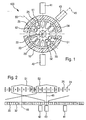
- FIG. 1 an embodiment of the electric machine 100 according to the invention is shown schematically in cross section.
- the stator is formed of two poles 10. Within the pole 10, an armature 20 on an armature shaft 22 with a rotation axis 23 rotatably stored.
- the armature 20 is equipped with 12 anchor teeth 24 and 12 between the anchor teeth 24 armature grooves 25.
- a commutator 30 with commutator blades 32 rotatably mounted on the armature shaft 22 ( Fig. 2 ).
- three brushes 41, 42, 43 are provided, wherein the first and second brush 41, 42 are arranged diametrically to each other, while the third brush 43 in the direction of rotation by a certain angle less than 180 °, here for example 45 °, offset from the first brush 41 is arranged.
- the second brush 42 serves as a common brush or mass brush by cooperating with the first brush 41 at low speeds, and with the third brush 43 at high speeds.
- the commutator 30 has 12 commutator bars 32 and the armature 20 has 12 armature teeth 24 or armature slots 25.
- An armature coil is formed from two partial coils 51, 52, which are arranged symmetrically to each other with respect to an axis of symmetry 55 which passes through the center 23 of the axis of rotation 22 of the armature 20.
- the partial coils 51, 52 are therefore arranged substantially geometrically parallel to one another and at the same distance from the axis of rotation 22 of the armature 20.
- the two sub-coils 51, 52 are connected to two adjacent commutator blades 32 of a commutator 30.
- the third brush 43, the two adjacent Kommutatorlamellen 32 (in Fig. 2 Slat 3 and blade 4) contacted the two sub-coils 51, 52 are short-circuited.
- the two adjacent Kommutatorlamellen 32 forms the third brush 43 with the center 23 of the armature shaft 22 has an axis 45 which is perpendicular to the axis of symmetry 55 of the two coil sections 51, 52 ( Fig. 1 ).
- the winding scheme according to Fig. 2 shows a partial development of a first embodiment of armature coils of two sub-coils 51, 52.
- the armature coil is wound in the manner of the loop winding in the form of a tendon winding.
- the winding of a first partial coil 51 is located in the Ankernut designated by 3 25 and the Ankernut designated 8 8.
- the winding of a second coil part 52 is located in the Ankernut designated by 2 25 and the Ankernut designated with 9.
- the two ends of the first and second sub-coil 51, 52 are electrically connected to adjacent (here the third and fourth) commutator blades 32.
- the two sub-coils 51, 52 are therefore in series connected.
- the third and eighth anchoring groove 25 and the second and ninth anchor groove 25 are opposite to each other, so that the two partial coils 51, 52 with respect to an axis passing through the center 23 of the armature shaft 22 are arranged symmetrically to each other.
- the two partial coils 51, 52 are arranged substantially parallel to one another, so that they are in a symmetrical position with respect to an axis of symmetry 55 arranged parallel to the partial coils 51, 52.
- the two partial coils 51, 52 are wound in the opposite direction of the winding.
- Fig. 2 shows an embodiment of a series connection of the two partial coils 51, 52. According to the illustrated principle of the winding of two symmetrically arranged partial coils 51, 52 further winding schemes can be realized.
Landscapes
- Engineering & Computer Science (AREA)
- Power Engineering (AREA)
- Dc Machiner (AREA)
- Windings For Motors And Generators (AREA)
- Motor Or Generator Current Collectors (AREA)
Description
- Die Erfindung betrifft eine elektrische Maschine, insbesondere eine Gleichstrommaschine, nach dem Oberbegriff des Anspruchs 1.
- Aus
WO 2005/076442 A ist ein elektrischer Motor mit einer symmetrisch angeordneten Ankerwicklung bekannt. Die symmetrisch angeordnete Ankerwicklung besteht aus einer ersten Spule, die zwischen zwei beliebigen Ankernuten gewickelt ist und an benachbarten Kommutatorlamellen elektrisch kontaktiert ist. Eine zweite Spule ist zwischen zwei Ankernuten gewickelt, die zu den beiden Ankernuten der ersten Spule in Bezug auf den Mittelpunkt der Ankerwelle in punktsymmetrischer Stellung stehen und in entgegengesetzter Richtung gewickelt ist. Bei dem Motor ist die Anzahl der Ankernuten gleich der Anzahl der Kommutatorlamellen. Der Motor hat je eine Bürste für hohe und niedrige Geschwindigkeiten sowie eine gemeinsame Bürste. Die erste und zweite Spule sind derart angeordnet, dass sie sich in einer symmetrischen Stellung zu einer den Mittelpunkt der Bürste für hohe Geschwindigkeiten und den Mittelpunkt der Drehwelle durchgehenden Achse befinden, wenn die Bürste für hohe Geschwindigkeiten in Kontakt mit der benachbarten Kommutatorlamelle kommt und dadurch die erste Spule mit der zweiten Spule kurzgeschlossen wird. - Die Anordnung der Bürsten bezüglich der symmetrisch zueinander angeordneten ersten und zweiten Spule gemäß
WO 2005/076442 hat den Nachteil, dass jeweils ein Schaltleiter jeder Spule direkt von der Ankernut an den Kommutator geführt wird. Unter einem Schaltleiter wird dabei der Abschnitt eines Spulendrahts verstanden, der von der Spule an den Kommutator geführt wird. Dies bedeutet, dass dieser Schaltleiter zwischen Spule und Kommutatorhaken quasi frei gespannt ist. Der gespannte Schaltleiter versperrt so den Platz für die nachfolgenden Schaltleiter der übrigen Spulen. Dies führt zu einem großen Wickelkopfaufbau und ggf. zu Drahtbruch an den Kommutatorhaken der gespannten Schaltleiter unter Schwingbelastung, was zu Feldausfällen führen kann. - Die erfindungsgemäße elektrische Maschine umfasst einen Anker mit Ankernuten zur Aufnahme von Ankerspulen. Wenigstens eine Ankerspule ist aus zwei bezüglich einer Symmetrieachse, die durch den Mittelpunkt der Ankerwelle des Ankers verläuft, symmetrisch zueinander angeordnete Teilspulen gebildet, wobei die Teilspulen mit zwei benachbarten Kommutatorlamellen eines Kommutators verbunden sind. Dies bedeutet, dass die Ankerspulen so ausgebildet sind, dass jeweils zwei Teilspulen bezüglich einer Symmetrieachse, die durch den Mittelpunkt der Drehachse des Ankers verläuft, symmetrisch zueinander angeordnet sind. Die beiden symmetrisch zueinander angeordneten Teilspulen sind mit zwei benachbarten Kommutatorlamellen eines Kommutators verbunden. Die elektrische Maschine umfasst ferner eine erste Bürste, eine zweite Bürste und eine dritte Bürste, welche gleitbar an dem Kommutator anliegen, wobei die zweite Bürste mit der ersten Bürste oder der dritten Bürste zusammenwirkt. Erfindungsgemäß ist die dritte Bürste relativ zu den beiden Teilspulen derart angeordnet, dass beim Kontaktieren der beiden benachbarten Kommutatorlamellen die dritte Bürste mit dem Mittelpunkt der Drehachse eine Achse bildet, welche zu der Symmetrieachse der beiden Teilspulen einen Winkel von

bis
- Beträgt die Anzahl der Lamellen z.B. 12, so liegt der Winkel in einem Bereich von 90°-15°-5° bis 90°+15°+5°, bevorzugt in einem Bereich von 90°-15°-4° bis 90°+15°+4°, besonders bevorzugt von 90°-15°-2° bis 90°+15°+2°. Der Winkel beträgt beispielsweise 90°+15°+/-4°.
- Erfindungsgemäß steht die Achse, die durch die dritte Bürste und den Mittelpunkt der Drehachse geht, wenn die dritte Bürste die beiden benachbarten Kommutatorlamellen kontaktiert, so dass die beiden Teilspulen kurzgeschlossen sind, im Wesentlichen senkrecht, d.h. 90°, zu der Symmetrieachse der beiden Teilspulen.
- Die beiden Schaltleiter der beiden symmetrischen Teilspulen in Reihenschaltung bzw. die vien Schaltleiter der beiden Teilspulen in Parallelschaltung werden nach dem Austreten aus der Ankernut um ca. 180° um die Ankerwelle geführt, bevor sie mit den jeweiligen Kommutatorhaken verbunden werden. Dadurch ist gewährleistet, dass die Schaltleiter nicht frei gespannt sind, sondern in ihrer gesamten Länge entweder auf der Ankerwelle oder auf Schaltleitern von zuvor gewickelten Spulen liegen. Diese zumindest teilweise Umwicklung der Ankerwelle durch die Spulenenden im Bereich des Wickelkopfes zwischen Anker und Kommutator wird auch als Umhakenwicklung bezeichnet.
- Die erfindungsgemäße elektrische Maschine hat den Vorteil, dass der Wickelkopf zwischen Anker und Kommutator im Vergleich zum Stand der Technik stabiler und kompakter aufgebaut ist. Durch die Umhakenwicklung wird insbesondere das Schwingen der Schaltleiter unter Schüttelbelastung vermieden, wodurch Drahtbruch an den Schaltleitern vermieden wird. Dies bedingt insgesamt einen robusteren Wickelkopfaufbau und ein reduziertes Feldrisiko.
- Gegenüber dieser im Wesentlichen senkrechten Anordnung zwischen der Achse, die durch die dritte Bürste und den Mittelpunkt der Drehachse geht, wenn die dritte Bürste die beiden benachbarten Kommutatorlamellen kontaktiert, und der Symmetrieachse der beiden Teilspulen ist der Kommutator relativ zu dem Anker vorzugsweise zusätzlich um einen Winkel im Bereich von

- Bei der Auslegung der Ankerwicklung wird zunächst aufgrund der Drehzahlanforderung der geringeren Drehzahlstufe die Anzahl der Leiter, d.h. die Anzahl der Wicklungen, pro Ankernut und die Spulendrahtstärke festgelegt. Die Drehzahl der höheren Drehzahlstufe in Relation zu der Drehzahl der geringeren Drehzahlstufe, der sogenannte Drehzahlsprung, wird durch die Winkelposition der dritten Bürste in Relation zu ersten Bürste festgelegt, wodurch bei unveränderter geringer Drehzahlstufe die höhere Drehzahlstufe grob auf den gewünschten Wert eingestellt werden kann. Diese Winkelposition ist typischerweise in einem Werkzeug festgelegt und liegt damit in der Regel für eine ganze Baureihe einer elektrischen Maschine fest und ist nur mittels einer Werkzeugänderung veränderbar.
- Eine Feinabstimmung des Drehzahlsprungs kann durch eine zusätzliche Kommutatorverdrehung um einen Winkel von - (180°/3·Lamellenanzahl) bis + (180°/3·Lamellenanzahl) erreicht werden. Eine Kommutatorverdrehung um etwa 1° bewirkt beispielsweise eine Veränderung der höheren Drehzahlstufe um etwa 1 Umdrehung pro Minute.
- Die erfindungsgemäße elektrische Maschine weist drei Bürsten auf. Die erste und zweite Bürste sind im Wesentlichen diametral zueinander angeordnet. Die dritte Bürste ist radial zwischen den einander gegenüberliegenden Bürsten angeordnet, so dass die dritte Bürste gegenüber der ersten Bürste in Drehrichtung um einen bestimmten Winkel kleiner als 180°, z.B. 70°, versetzt angeordnet ist. Dabei werden in der niedrigen Drehzahlstufe die beiden einander gegenüber liegenden Bürsten, d.h. die erste und zweite Bürste, bestromt, während die dritte Bürste stromlos ist. In der hohen Drehzahlstufe werden die zweite und die dritte Bürste bestromt, wohingegen die erste Bürste stromlos ist. Die zweite Bürste bildet demnach die gemeinsame Bürste, welche bei niedrigen Drehzahlen mit der ersten Bürste und bei hohen Drehzahlen mit der dritten Bürste zusammenwirkt. Die jeweils unbestromte Bürste verbindet jeweils zwei benachbarte Kommutatorlamellen. Sie schließt dadurch bei einer herkömmlichen Wicklung die dazwischen liegende Spule kurz, wobei sich ein Kurzschlussstrom ausbildet, der dem Speisestrom entgegen gesetzt gerichtet ist und zu einer Radialkraft auf den Anker führt. Diese Radialkraft wird bei der erfindungsgemäßen elektrischen Maschine vermieden, da anstelle einer Spule zwei symmetrisch zueinander angeordnete Teilspulen an benachbarten Kommutatorlamellen anliegen. Werden zwei benachbarte Kommutatorlamellen durch die jeweils unbestromte Bürste verbunden, tritt ein Kurzschlussstrom in beiden Teilspulen auf, sodass sich die Radialkräfte der beiden Teilspulen kompensieren.
- Die beiden Teilspulen sind erfindungsgemäß derart symmetrisch zueinander angeordnet, dass bei Bestromung der Teilspulen in einem Magnetfeld im Wesentlichen keine radialen Kräfte auf den Anker wirken. Die beiden Teilspulen sind gleichzeitig kommutierbar, beispielsweise indem sie an benachbarte Kommutatorlamellen angeschlossen sind. Die resultierenden Radialkräfte werden besonders gut dadurch kompensiert, dass die beiden Teilspulen im Wesentlichen geometrisch parallel zueinander und in gleichem Abstand zur Drehachse des Ankers angeordnet sind. Außerdem lassen sich die Radialkräfte besonders gut dadurch kompensieren, dass die beiden Teilspulen gleich viele Windungen aufweisen. Die Radialkräfte lassen sich ferner besonders gut kompensieren, indem die beiden Teilspulen in umgekehrtem Wickelsinn zueinander gewickelt sind. Insbesondere handelt es sich um eine zweipolige elektrische Wicklung.
- Die beiden Teilspulen können entweder elektrisch in Reihe oder parallel zueinander geschaltet sein. Bei der Reihenschaltung weisen die beiden Teilspulen zwei Enden auf, die mit benachbarten Kommutatorlamellen verbunden sind. Bei der Parallelschaltung hingegen weist jede der beiden Teilspulen zwei Enden auf, wobei jeweils die Enden einer Teilspule mit benachbarten Kommutatorlamellen verbunden sind.
- In einer bevorzugten Ausführungsform weist der Kommutator eine gerade Anzahl an Lamellen auf. Weiterhin ist bevorzugt die Anzahl der Lamellen gleich der Anzahl der Ankernuten.
- In einer weiteren bevorzugten Ausführungsform sind die symmetrisch angeordneten Teilspulen als Doppelwicklung mit reduziertem, z.B. mit dem halben, Spulendrahtquerschnitt in zwei Lagen ausgebildet. Dadurch kann ein erhöhter Nutfüllfaktor erzielt werden.
- Die erfindungsgemäße elektrische Maschine kann insbesondere als Scheibenwischermotor in Kraftfahrzeugen eingesetzt werden.
- Nachfolgend wird die Erfindung anhand der beigefügten Zeichnungen näher erläutert. Es zeigen:
- Figur 1
- einen schematischen Querschnitt durch eine Ausführungsform der erfindungsgemäßen elektrischen Maschine
- Figur 2
- eine Ausführungform eines Wickelschemas der erfmdungsgemäßen elektrischen Maschine
- In
Fig. 1 ist eine Ausführungsform der erfindungsgemäßen elektrischen Maschine 100 schematisch im Querschnitt dargestellt. Der Stator ist aus zwei Polen 10 gebildet. Innerhalb der Pole 10 ist ein Anker 20 auf einer Ankerwelle 22 mit einer Drehachse 23 drehfest gelagert. Der Anker 20 ist mit 12 Ankerzähnen 24 und 12 zwischen den Ankerzähnen 24 liegenden Ankernuten 25 ausgestattet. Außerdem ist ein Kommutator 30 mit Kommutatorlamellen 32 drehfest auf der Ankerwelle 22 befestigt (Fig. 2 ). Des Weiteren sind drei Bürsten 41, 42, 43 vorgesehen, wobei die erste und zweite Bürste 41, 42 zueinander diametral angeordnet sind, während die dritte Bürste 43 in Drehrichtung um einen bestimmten Winkel kleiner als 180°, hier z.B. 45°, versetzt zu der ersten Bürste 41 angeordnet ist. Die zweite Bürste 42 dient als gemeinsame Bürste oder Massebürste, indem sie bei niedrigen Drehzahlen mit der ersten Bürste 41, bei hohen Drehzahlen mit der dritten Bürste 43 zusammenwirkt. - In der dargestellten Ausführungsform gemäß
Fig. 1 und 2 hat der Kommutator 30 12 Kommutatorlamellen 32 und der Anker 20 12 Ankerzähne 24 bzw. Ankernuten 25. - Eine Ankerspule ist aus jeweils zwei Teilspulen 51, 52 gebildet, die bezüglich einer Symmetrieachse 55, die durch den Mittelpunkt 23 der Drehachse 22 des Ankers 20 verläuft, symmetrisch zueinander angeordnet sind. Die Teilspulen 51, 52 sind demnach im Wesentlichen geometrisch parallel zueinander und in gleichem Abstand zur Drehachse 22 des Ankers 20 angeordnet.
- Wie in
Fig. 2 ersichtlich, sind die beiden Teilspulen 51, 52 mit zwei benachbarten Kommutatorlamellen 32 eines Kommutators 30 verbunden. Wenn die dritte Bürste 43 die beiden benachbarten Kommutatorlamellen 32 (inFig. 2 Lamelle 3 und Lamelle 4) kontaktiert, werden die beiden Teilspulen 51, 52 kurzgeschlossen. Beim Kontaktieren der beiden benachbarten Kommutatorlamellen 32 bildet die dritte Bürste 43 mit dem Mittelpunkt 23 der Ankerwelle 22 eine Achse 45, welche zur Symmetrieachse 55 der beiden Teilspulen 51, 52 senkrecht steht (Fig. 1 ). - Das Wickelschema gemäß
Fig. 2 zeigt eine teilweise Abwicklung einer ersten Ausführungsform von Ankerspulen aus zwei Teilspulen 51, 52. Die Ankerspule ist nach Art der Schleifenwicklung in Form einer Sehnenwicklung gewickelt. Die Wicklung einer ersten Teilspule 51 liegt in der mit 3 bezeichneten Ankernut 25 und der mit 8 bezeichneten Ankernut 25. Die Wicklung einer zweiten Teilspule 52 liegt in der mit 2 bezeichneten Ankernut 25 und der mit 9 bezeichneten Ankernut 25. Die beiden Enden der ersten und zweiten Teilspule 51, 52 sind mit benachbarten (hier der dritten und vierten) Kommutatorlamellen 32 elektrisch verbunden. Die beiden Teilspulen 51, 52 sind demnach in Reihe geschaltet. Die dritte und achte Ankernut 25 sowie die zweite und neunte Ankernut 25 liegen einander gegenüber, so dass die beiden Teilspulen 51, 52 bezüglich einer Achse, die durch den Mittelpunkt 23 der Ankerwelle 22 geht, symmetrisch zueinander angeordnet sind. Die beiden Teilspulen 51, 52 sind im Wesentlichen parallel zueinander angeordnet, so dass sie sich bezüglich einer parallel zu den Teilspulen 51, 52 angeordneten Symmetrieachse 55 in symmetrischer Stellung befinden. Die beiden Teilspulen 51, 52 sind in umgekehrtem Wickelsinn gewickelt. -
Fig. 2 zeigt eine Ausführungsform einer Reihenschaltung der beiden Teilspulen 51, 52. Nach dem dargestellten Prinzip der Wicklung zweier symmetrisch angeordneter Teilspulen 51, 52 sind weitere Wicklungsschemata realisierbar.
Claims (6)
- Elektrische Maschine umfassend einen Anker (20) mit Ankernuten (25) zur Aufnahme von Ankerspulen, wobei wenigstens eine Ankerspule aus zwei bezüglich einer Symmetrieachse (55), die durch den Mittelpunkt (23) der Ankerwelle (22) des Ankers (20) verläuft, symmetrisch zueinander angeordnete Teilspulen (51, 52) gebildet ist, wobei die Teilspulen (51, 52) mit zwei benachbarten Kommutatorlamellen (32) eines Kommutators (30) verbunden sind, sowie eine erste Bürste (41), eine zweite Bürste (42) und eine dritte Bürste (43), welche gleitbar an dem Kommutator (30) anliegen, wobei die zweite Bürste (42) mit der ersten Bürste (41) oder der dritten Bürste (43) zusammenwirkt, dadurch gekennzeichnet, dass die dritte Bürste (43) relativ zu den beiden Teilspulen (51, 52) derart angeordnet ist, dass beim Kontaktieren der beiden benachbarten Kommutatorlamellen (30) die dritte Bürste (43) mit dem Mittelpunkt (23) der Ankerwelle (22) eine Achse (45) bildet, welche zu der Symmetrieachse (55) der beiden Teilspulen (51, 52) einen Winkel von


- Elektrische Maschine nach Anspruch 1, dadurch gekennzeichnet, dass die beiden Teilspulen (51, 52) im Wesentlichen geometrisch parallel zueinander angeordnet sind.
- Elektrische Maschine nach einem der Ansprüche 1 oder 2, dadurch gekennzeichnet, dass die beiden Teilspulen (51, 52) gleich viele Windungen aufweisen.
- Elektrische Maschine nach einem der vorhergehenden Ansprüche, dadurch gekennzeichnet, dass die beiden Teilspulen (51, 52) in umgekehrtem Wickelsinn zueinander gewickelt sind.
- Elektrische Maschine nach einem der Ansprüche 1-4, dadurch gekennzeichnet, dass die beiden Teilspulen (51, 52) elektrisch in Reihe geschaltet sind.
- Elektrische Maschine nach Anspruch 5, dadurch gekennzeichnet, dass die beiden in Reihe geschalteten Teilspulen (51, 52) zwei Enden aufweisen, die mit benachbarten Kommutatorlamellen (32) verbunden sind.
Applications Claiming Priority (2)
| Application Number | Priority Date | Filing Date | Title |
|---|---|---|---|
| DE102006011547A DE102006011547A1 (de) | 2006-03-14 | 2006-03-14 | Elektrische Maschine |
| PCT/EP2007/050483 WO2007104591A1 (de) | 2006-03-14 | 2007-01-18 | Elektrische maschine |
Publications (2)
| Publication Number | Publication Date |
|---|---|
| EP1997215A1 EP1997215A1 (de) | 2008-12-03 |
| EP1997215B1 true EP1997215B1 (de) | 2013-03-13 |
Family
ID=37944562
Family Applications (1)
| Application Number | Title | Priority Date | Filing Date |
|---|---|---|---|
| EP07726203A Active EP1997215B1 (de) | 2006-03-14 | 2007-01-18 | Elektrische maschine |
Country Status (6)
| Country | Link |
|---|---|
| US (1) | US7919899B2 (de) |
| EP (1) | EP1997215B1 (de) |
| JP (1) | JP2009529854A (de) |
| KR (2) | KR101133461B1 (de) |
| DE (1) | DE102006011547A1 (de) |
| WO (1) | WO2007104591A1 (de) |
Families Citing this family (9)
| Publication number | Priority date | Publication date | Assignee | Title |
|---|---|---|---|---|
| JP5414318B2 (ja) * | 2008-06-30 | 2014-02-12 | 株式会社ミツバ | 電動モータ |
| USRE45912E1 (en) * | 2008-06-30 | 2016-03-01 | Mitsuba Corporation | Electric motor |
| WO2010058851A1 (ja) * | 2008-11-21 | 2010-05-27 | アスモ株式会社 | モータ及びブラシの設定方法 |
| FR2959360B1 (fr) * | 2010-04-27 | 2013-01-18 | Valeo Equip Electr Moteur | Machine electrique comportant un rotor muni d'un bobinage permettant de faciliter la commutation, et demarreur associe |
| DE102014118185A1 (de) * | 2014-12-09 | 2016-06-09 | Valeo Systèmes d'Essuyage | Kommutatormotor, Verfahren zum Herstellen eines Kommutatormotors und Scheibenwischermotor |
| CN107147236B (zh) * | 2017-07-14 | 2023-06-13 | 成都华川电装有限责任公司 | 电机刷架及有刷直流电机 |
| US9941651B1 (en) * | 2017-09-25 | 2018-04-10 | Chris Coody | Systems and methods for generating electric power with an electric motor |
| US20210057965A1 (en) * | 2019-08-20 | 2021-02-25 | Nidec Motors & Actuators (Germany) Gmbh | Noise reduction for direct current excited brushed asymmetric motor |
| US11818117B2 (en) | 2021-07-20 | 2023-11-14 | Bank Of America Corporation | Multi-party exchange platform |
Family Cites Families (7)
| Publication number | Priority date | Publication date | Assignee | Title |
|---|---|---|---|---|
| US3733506A (en) * | 1971-10-29 | 1973-05-15 | Singer Co | Commutated wound armature assemblies |
| US5485049A (en) * | 1994-05-25 | 1996-01-16 | United Technologies Motor Systems, Inc. | Multi-speed motor |
| US6580237B2 (en) | 2000-12-25 | 2003-06-17 | Asmo Co., Ltd | Direct-current motor and manufacturing method of the same |
| JP3839428B2 (ja) * | 2003-06-10 | 2006-11-01 | アスモ株式会社 | 直流機 |
| JP4772508B2 (ja) * | 2004-02-10 | 2011-09-14 | 株式会社ミツバ | 電動モータ |
| US7265475B2 (en) | 2004-03-30 | 2007-09-04 | Trico Products Corporation | Electric motor having convex high-speed brush |
| JP4613091B2 (ja) * | 2005-04-27 | 2011-01-12 | 株式会社マキタ | モータおよびモータの製造方法 |
-
2006
- 2006-03-14 DE DE102006011547A patent/DE102006011547A1/de not_active Withdrawn
-
2007
- 2007-01-18 WO PCT/EP2007/050483 patent/WO2007104591A1/de not_active Ceased
- 2007-01-18 KR KR1020117024203A patent/KR101133461B1/ko not_active Expired - Fee Related
- 2007-01-18 US US12/280,909 patent/US7919899B2/en not_active Expired - Fee Related
- 2007-01-18 EP EP07726203A patent/EP1997215B1/de active Active
- 2007-01-18 JP JP2008558737A patent/JP2009529854A/ja not_active Ceased
- 2007-01-18 KR KR1020087022411A patent/KR101165281B1/ko not_active Expired - Fee Related
Also Published As
| Publication number | Publication date |
|---|---|
| KR20110128928A (ko) | 2011-11-30 |
| KR101133461B1 (ko) | 2012-04-09 |
| DE102006011547A1 (de) | 2007-09-20 |
| US7919899B2 (en) | 2011-04-05 |
| US20090009023A1 (en) | 2009-01-08 |
| KR20080105081A (ko) | 2008-12-03 |
| KR101165281B1 (ko) | 2012-07-19 |
| JP2009529854A (ja) | 2009-08-20 |
| WO2007104591A1 (de) | 2007-09-20 |
| EP1997215A1 (de) | 2008-12-03 |
Similar Documents
| Publication | Publication Date | Title |
|---|---|---|
| EP3402047B1 (de) | Schneid-klemm-kontakt | |
| EP1997215A1 (de) | Elektrische maschine | |
| EP1702401A1 (de) | Elektrische maschine mit kommutatorläufer | |
| EP2248246A1 (de) | Verfahren zur herstellung der läuferwicklung einer elektrischen maschine sowie elektrische maschine mit einer nach diesem verfahren hergestellten läuferwicklung | |
| WO2019020659A1 (de) | Verfahren zum montieren einer schalteinheit an einer komponente eines elektromotors | |
| DE102006011550A1 (de) | Elektrische Maschine | |
| WO2007104589A1 (de) | Elektrische maschine | |
| DE102014217289A1 (de) | Wicklungsanordnung und Verfahren zur Herstellung einer Wicklungsanordnung | |
| WO2013023819A2 (de) | Elektrische maschine | |
| DE3320805C2 (de) | ||
| WO2019170751A1 (de) | Statoranordnung mit wicklungsanordnung | |
| WO2016023934A1 (de) | Verfahren zum herstellen eines bürstenkommutierten gleichstrommotors | |
| DE102010064323A1 (de) | Anker für eine elektrische Maschine, Herstellungsverfahren dafür und elektrische Maschine | |
| WO2014184180A2 (de) | Bürstenkommutierter gleichstrommotor | |
| DE102006061673A1 (de) | Elektrischer Vierpolmotor | |
| DE102009017870B4 (de) | Stator für einen Gleichstrommotor | |
| DE202006003982U1 (de) | Elektrische Maschine | |
| DE102005035411A1 (de) | Elektrische Maschine | |
| WO2021219368A1 (de) | Stator für eine elektrische maschine und elektrische maschine mit einem stator | |
| DE102010044713A1 (de) | Bürstenloser Gleichstrommotor | |
| DE102019122347B4 (de) | Kohlebürste für einen gleichstromerregten bürstenbehafteten Motor mit einer einzigen schmalen Anlauffläche | |
| EP3525322A1 (de) | Stabwicklung für einen stator einer elektrischen rotierenden maschine | |
| DE102019122348B4 (de) | Gleichstromerregter bürstenbehafteter Motor mit asymmetrischer Teilung aufweisend Dreischichtbürsten | |
| DE102018125827A1 (de) | Stator für eine elektrische Maschine | |
| WO2022161788A1 (de) | Verfahren und vorrichtung zum herstellen eines stators für einen bürstenloser gleichstrommotor |
Legal Events
| Date | Code | Title | Description |
|---|---|---|---|
| PUAI | Public reference made under article 153(3) epc to a published international application that has entered the european phase |
Free format text: ORIGINAL CODE: 0009012 |
|
| 17P | Request for examination filed |
Effective date: 20081014 |
|
| AK | Designated contracting states |
Kind code of ref document: A1 Designated state(s): DE FR |
|
| RBV | Designated contracting states (corrected) |
Designated state(s): DE FR |
|
| 17Q | First examination report despatched |
Effective date: 20100720 |
|
| DAX | Request for extension of the european patent (deleted) | ||
| GRAP | Despatch of communication of intention to grant a patent |
Free format text: ORIGINAL CODE: EPIDOSNIGR1 |
|
| GRAS | Grant fee paid |
Free format text: ORIGINAL CODE: EPIDOSNIGR3 |
|
| GRAA | (expected) grant |
Free format text: ORIGINAL CODE: 0009210 |
|
| AK | Designated contracting states |
Kind code of ref document: B1 Designated state(s): DE FR |
|
| REG | Reference to a national code |
Ref country code: DE Ref legal event code: R096 Ref document number: 502007011463 Country of ref document: DE Effective date: 20130502 |
|
| PLBE | No opposition filed within time limit |
Free format text: ORIGINAL CODE: 0009261 |
|
| STAA | Information on the status of an ep patent application or granted ep patent |
Free format text: STATUS: NO OPPOSITION FILED WITHIN TIME LIMIT |
|
| 26N | No opposition filed |
Effective date: 20131216 |
|
| REG | Reference to a national code |
Ref country code: DE Ref legal event code: R097 Ref document number: 502007011463 Country of ref document: DE Effective date: 20131216 |
|
| REG | Reference to a national code |
Ref country code: FR Ref legal event code: PLFP Year of fee payment: 10 |
|
| REG | Reference to a national code |
Ref country code: FR Ref legal event code: PLFP Year of fee payment: 11 |
|
| REG | Reference to a national code |
Ref country code: FR Ref legal event code: PLFP Year of fee payment: 12 |
|
| PGFP | Annual fee paid to national office [announced via postgrant information from national office to epo] |
Ref country code: FR Payment date: 20200123 Year of fee payment: 14 |
|
| PG25 | Lapsed in a contracting state [announced via postgrant information from national office to epo] |
Ref country code: FR Free format text: LAPSE BECAUSE OF NON-PAYMENT OF DUE FEES Effective date: 20210131 |
|
| PGFP | Annual fee paid to national office [announced via postgrant information from national office to epo] |
Ref country code: DE Payment date: 20250317 Year of fee payment: 19 |