EP1997203B1 - System zur versorgung von elektrischen verbrauchern mit energie und daten - Google Patents
System zur versorgung von elektrischen verbrauchern mit energie und daten Download PDFInfo
- Publication number
- EP1997203B1 EP1997203B1 EP07722781.7A EP07722781A EP1997203B1 EP 1997203 B1 EP1997203 B1 EP 1997203B1 EP 07722781 A EP07722781 A EP 07722781A EP 1997203 B1 EP1997203 B1 EP 1997203B1
- Authority
- EP
- European Patent Office
- Prior art keywords
- voltage
- supply module
- phase
- loads
- line
- Prior art date
- Legal status (The legal status is an assumption and is not a legal conclusion. Google has not performed a legal analysis and makes no representation as to the accuracy of the status listed.)
- Active
Links
Images


Classifications
-
- H—ELECTRICITY
- H04—ELECTRIC COMMUNICATION TECHNIQUE
- H04B—TRANSMISSION
- H04B3/00—Line transmission systems
- H04B3/54—Systems for transmission via power distribution lines
-
- H—ELECTRICITY
- H04—ELECTRIC COMMUNICATION TECHNIQUE
- H04B—TRANSMISSION
- H04B2203/00—Indexing scheme relating to line transmission systems
- H04B2203/54—Aspects of powerline communications not already covered by H04B3/54 and its subgroups
- H04B2203/5404—Methods of transmitting or receiving signals via power distribution lines
- H04B2203/5412—Methods of transmitting or receiving signals via power distribution lines by modofying wave form of the power source
-
- H—ELECTRICITY
- H04—ELECTRIC COMMUNICATION TECHNIQUE
- H04B—TRANSMISSION
- H04B2203/00—Indexing scheme relating to line transmission systems
- H04B2203/54—Aspects of powerline communications not already covered by H04B3/54 and its subgroups
- H04B2203/5462—Systems for power line communications
- H04B2203/547—Systems for power line communications via DC power distribution
Definitions
- the invention relates to a system.
- the invention is therefore based on the object of developing a system for the decentralized supply of drives, with as cost as possible cabling should be foreseeable.
- Three-phase cables for the supply of consumers with a three-phase voltage system ie three-phase voltage system, are also known and inexpensive manufacturable.
- Essential features of the invention in the system are that it comprises a supply module via which consumers can be supplied with energy and data , wherein the consumers are connected to the supply module by means of at least three lines, wherein two of the lines form a power supply for the consumers and the third line is provided for data transmission.
- the advantage here is that a single supply module for an automation cell is necessary. So it drives with energy and information from such a module can be supplied via a wiring that includes only commercially available and therefore cost-effective three-phase cable.
- a 24V control voltage supply and / or a fieldbus connection is superfluous.
- the data are surprisingly exchangeable via a line of the three-phase cable.
- the laying of a single cable in the system is sufficient. There is no need to lay a separate cable for data transmission. Nevertheless, energy and information are separated from each other and not on the same physical carrier, in particular to reduce the interference in information transmission.
- a braking resistor is provided in the supply module for the destruction of excess Energy. This resistance is therefore centrally providable, making the consumer compact and inexpensive manufacturable.
- the drives can therefore be equipped without such an external braking resistor.
- the drives are additionally equipped with an integrated braking resistor.
- Another advantage is that the network interference and overvoltage protection can be provided centrally in the supply module.
- the respective drives therefore do not need these means and are therefore more compact, easier and cheaper to produce.
- the invention is therefore particularly advantageous for the simple and fast wiring of an automation cell usable, with low interference voltages to occur during data transmission.
- a single-phase AC voltage or a unipolar voltage, such as DC voltage or the like, is provided as the voltage supply via the two lines.
- a unipolar voltage such as DC voltage or the like.
- the consumers are connected to the supply module by means of a three-wire three-phase cable.
- the advantage here is that known commercially available three-phase cables can be used.
- the supply module comprises means for producing a unipolar voltage, in particular DC link voltage.
- a unipolar voltage in particular DC link voltage.
- the third line can be brought to two different electrical potentials, in particular for digital data transmission.
- the advantage here is that the positive or negative potential of the DC link voltage can be switched to the data line and thus digital information is transferable.
- the supply module and / or a drive comprises at least one transmitting and / or one receiving circuit, which are provided for data transmission via the third line.
- the third line is galvanically isolated and is essentially undisturbed by the interference voltages that can occur on the power lines.
- the supply module comprises a braking resistor.
- the drive comprises a converter and an electric motor that can be supplied by it.
- the advantage here is that a regulated and thus well controllable drive is provided, in particular a drive with high efficiency.
- the supply module comprises a rectifier and a smoothing capacitor, in particular intermediate circuit capacitor, for producing the unipolar voltage.
- a rectifier and a smoothing capacitor, in particular intermediate circuit capacitor, for producing the unipolar voltage.
- an output stage comprising electronic power semiconductor switch
- IGBT or similar low-loss switch can be used.
- each drive comprises a braking resistor.
- the advantage here is that the braking resistor is integrated executable and the heat is spread over the entire system. Thus, the heat removal problem of high temperature level components is mitigated.
- the cabling between the supply module and drives comprises three-phase cables and three-phase distribution boxes, in particular for the T-shaped three-phase current distribution.
- the T-shaped three-phase distribution is realized within the consumer.
- the three-phase wiring must be looped through the consumer, so that the next downstream consumer can be connected.
- the housing of the consumer also includes the T-point. So it is not necessary a separate housing for the T-distribution.
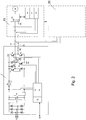
- FIG. 1 a system according to the invention is shown schematically.
- the system comprises a supply module 1, which can be supplied by the network via the mains supply 5 and via a data line 6 with a PLC or other computer for data exchange is connectable.
- the supply module comprises a rectifier, to which a network interference suppression 2 is arranged downstream.
- An intermediate circuit capacitor 3 is provided for smoothing the unipolar rectified voltage.
- the intermediate circuit capacitor 3, a low / boost converter 4 are arranged downstream for the production of the desired intermediate circuit voltage from which the power amplifier is supplied.
- a braking resistor R_BR is provided which can be switched on or off via an electronic semiconductor switch, such as an IGBT transistor or the like.
- the control circuit 8 is provided. This is connected to means for detecting the intermediate circuit voltage and the DC link current.
- the switch is voltage-dependent controllable.
- a measure of the electrical power can be determined. This can also be used for regulation.
- the DC link current detection is performed on the upper and lower potential of the DC link voltage.
- overcurrent detection is foreseeable but also a ground fault detection.
- the consumers thus do not need their own such detections, in particular no earth fault detection.
- From the PLC or the other higher-level computer data is transferable to the communication and control unit 7, which is connected to the control circuit 8.
- the data line 6 is executed accordingly.
- the output stage includes switches for connecting or disconnecting the intermediate circuit voltage to the connected drives.
- the switches T2, T3 are provided. Two lines 11 of the three-phase cable thus supply the connected drives with DC voltage.
- the data line 12 is fed by a half-bridge of the output stage, which comprises two switches (T4, T5).
- the potential of this data line 12 can be applied to positive or negative potential (+ Uz, -Uz) of the intermediate circuit voltage. In this way, therefore, digital information is transferable.
- the transmission circuit 9 is provided and connected to the switches T4, T5 of the half-bridge. Accordingly, the receiving circuit 10 is connected to the data line 12 of the three-phase cable.
- Two of the three power lines of the three-phase cable are thus provided for the power supply of the drives and one of the lines for data transmission.
- the drives each comprise a motor M, which can be supplied from a converter 14 which can be operated with direct voltage, and a transmitting circuit 18 and a receiving circuit 19, which can be supplied from a supply part, such as power supply 17, and via a communication and control circuit 16 to the converter 14 are connected.
- the power supply can be supplied from the three-phase cable, in particular from the lines 11.
- the supply module comprises a rectifier, to which the network interference suppression 2 is not arranged downstream but upstream of the network.
- the supply module has only one transmission unit and the respective drives have only reception units.
- the communication and control circuit 16 is executable as a simple protocol and / or level shifter.
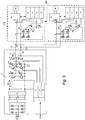
- the output stage comprises three half bridges, wherein the first two half bridges of the generation of a single-phase AC voltage are used, which is applied to the lines 11 for supplying the drives.
- the third half bridge is opposite FIG. 1 unchanged.
- the wiring in turn includes a commercially available three-phase cable.
- the first two half-bridges, each comprising two switches, are pulse-width-modulated or can be driven with square-wave voltage such that a single-phase alternating voltage can be generated in two lines of the three-phase cable, with which the connected drives (13 to 20) can be supplied.
- the advantage here is that the aging of the insulation system, comprising the three-phase cable and other insulation provided for components of the system is reduced by avoiding a permanently unipolar polarization.
- the drives require in this embodiment a rectifier and also a smoothing capacitor.
- the rectifier is single-phase.
- equivalently acting rectifiers are also usable, such as three-phase rectifiers or the like.
- the supply module comprises a matrix converter and is thus network-regenerative.
- the braking resistor R_BR can be saved.
- the supply module has an output stage with three half-bridges.
- the drives can be equipped with a single-phase rectifier.
- the third line 12 is as well as at FIG. 2 used for data transmission.
- the supply module 40 only a loop through three-phase cables, with a network interference is provided.
- two of the lines of the three-phase power supply becomes a DC voltage generated and fed to a half-bridge.
- This is connected to the third line 42 of the three-phase cabling for feeding a data transmission signal.
- the third line is the neutral of a three-phase cable, which provides three lines 41, namely the first, second and fourth line, for the three-phase phases and also comprises a neutral conductor and a PE conductor.
- the supply module is designed without looping, so the three-phase cabling is performed outside the supply module.
- the DC voltage is generated from three of the lines of the three-phase power supply.
- the network interference in the consumer is arranged in each case.
- the supply module is supplied from another source, for example from an independent 24 V supply in the industrial plant or the like.
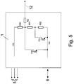
- FIG. 5 is an advantageous modification of the output half-bridge for data signal generation of FIG. 2 or the other figures shown.
- the switches T3, T4 are replaced by the circuit of FIG. 5 .
- the resistors R50, R51, R52 are connected in series for voltage division.
- the switches T50 and T51 With which parts of the series circuit can be short-circuited, three different potentials can be generated.
- the information is transferable, the coding is not binary but tertiary.
- further potentials for the data transmission can be generated instead of the three potentials that can be generated.
Landscapes
- Engineering & Computer Science (AREA)
- Power Engineering (AREA)
- Computer Networks & Wireless Communication (AREA)
- Signal Processing (AREA)
- Inverter Devices (AREA)
- Dc Digital Transmission (AREA)
- Remote Monitoring And Control Of Power-Distribution Networks (AREA)
- Cable Transmission Systems, Equalization Of Radio And Reduction Of Echo (AREA)
Description
- Die Erfindung betrifft ein System.
- Aus der
DE 199 21 654 ist ein System bekannt, bei dem Antriebe aus einem Versorgungsmodul mit Gleichspannung versorgbar sind. - Aus der
US 5 637 933 ist ein elektrisches System bekannt, das T-förmige Verteiler aufweist. - Aus der
DE 1 613 569 ist eine simultane Ausnutzung der Leitungen von Wechsel- oder Drehstromnetzen zur Energie- und Informationsübertragung bekannt. - Aus der
EP 0 664 598 A3 ist ein elektrisches Leistungsversorgungssystem bekannt. - Aus der
US 5 194 858 ist ein System zur Steuerung von elektrischer Leistung in einer Anlage bekannt. - Aus der
FR 2 684 250 - Aus der
DE 10 2004 043 186 A1 ist als nächstliegender Stand der Technik ein multifunktionelles integriertes Automatisierungskabelsystem bekannt. - Aus der
WO 02/43220 A1 - Der Erfindung liegt daher die Aufgabe zugrunde, ein System zur dezentralen Versorgung von Antrieben weiterzubilden, wobei eine möglichst kostengünstige Verkabelung vorsehbar sein soll.
- Drehstromkabel für die Versorgung von Verbrauchern mit einem dreiphasigen Spannungssystem, also Drehspannungssystem, sind ebenfalls bekannt und kostengünstig fertigbar.
- Erfindungsgemäß wird die Aufgabe bei dem System nach den in Anspruch 1 angegebenen Merkmalen gelöst.
- Wesentliche Merkmale der Erfindung bei dem System sind, dass es ein Versorgungsmodul umfasst, über welches Verbraucher mit Energie und Daten versorgbar sind,
wobei die Verbraucher mit dem Versorgungsmodul mittels zumindest drei Leitungen verbunden sind,
wobei zwei der Leitungen eine Spannungsversorgung für die Verbraucher bilden und die dritte Leitung zur Datenübertragung vorgesehen ist. - Von Vorteil ist dabei, dass ein einziges Versorgungsmodul für eine Automatisierungszelle notwendig ist. Es sind also Antriebe mit Energie und Information aus einem solchem Modul versorgbar über eine Verkabelung, die nur handelsübliche und daher kostengünstige Drehstromkabel umfasst. Eine 24V Steuerspannungsversorgung und/oder ein Feldbusanschluss ist überflüssig. Die Daten werden überraschenderweise über eine Leitung des Drehstromkabels austauschbar. Somit ist die Verlegung eines einzigen Kabels in der Anlage ausreichend. Es muss kein separates Kabel für Datenübertragung verlegt werden. Trotzdem sind Energie und Information voneinander separiert und nicht auf demselben physikalischen Träger, insbesondere zur Verminderung der Störungen bei Informationsübertragung.
- Weiter ist vorteilhaft, dass die von einem Umrichter bei generatorischer Betriebsart des jeweiligen Antriebs, insbesondere bei Verwendung von rückspeisefähigen Umrichtern oder Matrix-Umrichtern, gegebenenfalls in die Drehstromkabel-Verkabelung rückgespeiste Energie anderen Antrieben zur Verfügung stellbar ist. Erfindungsgemäß ist im Versorgungsmodul einen Bremswiderstand vorgesehen zur Vernichtung überschüssiger Energie. Dieser Widerstand ist also zentral vorsehbar, wodurch die Verbraucher kompakter und kostengünstiger fertigbar sind. Außerdem ist deren Dichtungsproblematik vereinfacht. Die Antriebe sind also ohne einen solchen externen Bremswiderstand ausstattbar. Somit sind auch Probleme bei Dichtigkeit und der erhöhte Montageaufwand sowie die Materialkosten einsparbar.
- Erfindungsgemäß sind die Antriebe mit einem integrierten Bremswiderstand zusätzlich ausgestattet.
- Weiter vorteilig ist, dass die Netzentstörung und ein Überspannungsschutz zentral im Versorgungsmodul versehbar sind. Die jeweiligen Antriebe benötigen daher diese Mittel nicht und sind somit kompakter, einfacher und kostengünstiger herstellbar.
- Die Erfindung ist also besonders vorteilhaft zur einfachen und schnellen Verkabelung einer Automatisierungszelle verwendbar, wobei geringe Störspannungen bei der Datenübertragung auftreten sollen.
- Vorteilig ist auch, dass schon bestehende Verkabelungsstrukturen in Anlagen oder Maschinen für die Erfindung nutzbar sind. Es müssen also nur die entsprechenden Antriebe und das Versorgungsmodul in der Anlage eingebaut werden.
- Erfindungsgemäß sind Verbraucher elektrische Antriebe. Von Vorteil ist dabei, dass die Verbraucher steuerbar und mit hohem Wirkungsgrad betreibbar sind.
- Bei einer vorteilhaften Ausgestaltung ist als Spannungsversorgung über die beiden Leitungen eine einphasige Wechselspannung oder eine unipolare Spannung, wie Gleichspannung oder dergleichen, vorgesehen. Von Vorteil ist dabei, dass die Erfindung mit beiden Sorten von Versorgungsspannung wahlweise ausführbar ist.
- Bei einer vorteilhaften Ausgestaltung sind die Verbraucher mit dem Versorgungsmodul mittels eines drei Leitungen umfassenden Drehstromkabels verbunden. Von Vorteil ist dabei, dass bekannte handelsübliche Drehstromkabel verwendbar sind.
- Bei einer vorteilhaften Ausgestaltung umfasst das Versorgungsmodul Mittel zur Herstellung einer unipolaren Spannung, insbesondere Zwischenkreisspannung. Von Vorteil ist dabei, dass diese den Antrieben zur Verfügung stellbar ist.
- Bei einer vorteilhaften Ausgestaltung sind vom Versorgungsmodul oder einem jeweiligen Antrieb die dritte Leitung auf zwei verschiedene elektrische Potentiale bringbar, insbesondere zur digitalen Datenübertragung. Von Vorteil ist dabei, dass das positive oder negative Potential der Zwischenkreisspannung auf die Datenleitung schaltbar ist und somit digitale Information übertragbar ist.
- Bei einer vorteilhaften Ausgestaltung umfasst das Versorgungsmodul und/oder ein Antrieb zumindest eine Sende- und/oder eine Empfangsschaltung, die zur Datenübertragung über die dritte Leitung vorgesehen sind. Von Vorteil ist dabei, dass die dritte Leitung galvanisch getrennt ist und im Wesentlichen ungestört von den Störspannungen ist, welche auf den Energie-Leitungen auftreten können.
- Erfindungsgemäß umfasst das Versorgungsmodul einen Bremswiderstand. Von Vorteil ist dabei, dass ein einziger genügt für das gesamte System. Somit sind Dichtigkeitsprobleme bei den versorgten Antrieben vermeidbar, auch wenn sie generatorisch betreibbar sind.
- Bei einer vorteilhaften Ausgestaltung umfasst der Antrieb einen Umrichter und einen von diesem versorgbaren Elektromotor. Von Vorteil ist dabei, dass ein geregelter und somit gut steuerbarer Antrieb vorgesehen ist, insbesondere ein Antrieb mit hohem Wirkungsgrad.
- Bei einer vorteilhaften Ausgestaltung umfasst das Versorgungsmodul einen Gleichrichter und einen Glättungskondensator, insbesondere Zwischenkreiskondensator, zur Herstellung der unipolaren Spannung. Von Vorteil ist dabei, dass die Gleichspannung zur Versorgung der Wechselrichter-Endstufen der Antreibe zentral zur Verfügung stellbar ist.
- Bei einer vorteilhaften Ausgestaltung ist aus der unipolaren Spannung eine Endstufe, umfassend elektronische Leistungshalbleiterschalter, versorgbar. Von Vorteil ist dabei, dass IGBT oder ähnlich verlustarme Schalter verwendbar sind.
- Erfindungsgemäß umfasst jeder Antrieb einen Bremswiderstand. Von Vorteil ist dabei, dass der Bremswiderstand integriert ausführbar ist und die Wärme über die gesamte Anlage aufgespreizt ist. Somit ist das Wärmeabfuhrproblem von Komponenten hohen Temperaturniveaus entschärft.
- Erfindungsgemäß umfasst die Verkabelung zwischen Versorgungsmodul und Antrieben Drehstromkabel und Drehstrom-Verteilerkästen, insbesondere zur T-förmiger Drehstromverteilung. Von Vorteil ist dabei, dass einfache Mittel vorgesehen sind. Insbesondere sind schon bestehende Mittel bei Einführung der Erfindung verwendbar.
- Bei einer vorteilhaften Ausgestaltung ist die T-förmige Drehstromverteilung innerhalb der Verbraucher realisiert. Somit muss also die Drehstromverdrahtung durch den Verbraucher durchgeschleift werden, damit der nächste nachgeordnete Verbraucher anschließbar ist. Das Gehäuse des Verbrauchers umfasst dabei auch den T-Punkt. Es ist also kein separates Gehäuse für die T-Verteilung notwendig.
- Weitere Vorteile ergeben sich aus den Unteransprüchen.
- Die Erfindung wird nun anhand von Abbildungen näher erläutert:
In derFigur 1 ist eine erfindungsgemäße Anlage schematisch gezeichnet. - Dabei umfasst die Anlage ein Versorgungsmodul 1, das vom Netz versorgbar ist über die Netzversorgung 5 und über eine Datenleitung 6 mit einer SPS oder einem anderen Rechner zum Datenaustausch verbindbar ist.
- Das Versorgungsmodul umfasst einen Gleichrichter, dem eine Netzentstörung 2 nachgeordnet ist. Ein Zwischenkreiskondensator 3 ist zur Glättung der unipolar gleichgerichteten Spannung vorgesehen. Wahlweise kann dem Zwischenkreiskondensator 3 ein Tief/Hochsetzsteller 4 nachgeordnet werden zur Herstellung der gewünschten Zwischenkreisspannung, aus der die Endstufe versorgbar ist.
- Zur Regelung der Zwischenkreisspannung ist ein Bremswiderstand R_BR vorgesehen, der über einen elektronischen Halbleiterschalter, wie IGBT Transistor oder dergleichen, zu- oder abschaltbar ist. Zur Ansteuerung dieses Schalters ist die Steuerschaltung 8 vorgesehen. Diese ist mit Mitteln zur Erfassung der Zwischenkreisspannung und des Zwischenkreisstroms verbunden. Somit wird der Schalter spannungsabhängig ansteuerbar.
- Aus den erfassten Messwerten ist ein Maß für die elektrische Leistung bestimmbar. Dies ist auch zur Regelung verwendbar.
- Dabei ist die Zwischenkreisstromerfassung auf dem oberen und unteren Potential der Zwischenkreisspannung ausgeführt. Auf diese Weise ist nicht nur eine Kurzschlusserkennung, Überstromerkennung vorsehbar sondern auch eine Erdschlusserkennung. Die Verbraucher benötigen somit keine eigenen solchen Erkennungen, insbesondere keine Erdschlusserkennung.
- Von der SPS oder dem anderen übergeordneten Rechner sind Daten übertragbar an die Kommunikations- und Steuereinheit 7, die mit der Steuerschaltung 8 verbunden ist. Hierzu ist die Datenleitung 6 entsprechend ausgeführt.
- Die Endstufe umfasst Schalter zum Zuschalten oder Abschalten der Zwischenkreisspannung zu den verbundenen Antrieben. Hierzu sind die Schalter (T2, T3) vorgesehen. Zwei Leitungen 11 des Drehstromkabels versorgen somit die verbundenen Antriebe mit Gleichspannung.
- Die Datenleitung 12 wird von einer Halbbrücke der Endstufe gespeist, welche zwei Schalter (T4, T5) umfasst. Somit ist das Potential dieser Datenleitung 12 auf positives oder negatives Potential (+Uz, -Uz) der Zwischenkreisspannung legbar. Auf diese Weise ist daher digitale Information übertragbar. Hierzu ist die Sendeschaltung 9 vorgesehen und mit den Schaltern T4, T5 der Halbbrücke verbunden. Entsprechend ist die Empfangsschaltung 10 mit der Datenleitung 12 des Drehstromkabels verbunden.
- Zwei der drei Starkstromleitungen des Drehstromkabels sind also für die Leistungsversorgung der Antriebe und eine der Leitungen zur Datenübertragung vorgesehen.
- Die Antriebe umfassen jeweils einen Motor M, der aus einem mit Gleichspannung betreibbaren Umrichter 14 versorgbar ist und eine Sendeschaltung 18 und eine Empfangsschaltung 19, welche aus einem Versorgungsteil, wie Netzteil 17, versorgbar sind und über eine Kommunikations- und Steuerschaltung 16 mit dem Umrichter 14 verbunden sind. Das Netzteil ist aus dem Drehstromkabel versorgbar, insbesondere aus den Leitungen 11.
- Bei weiteren erfindungsgemäßen Ausführungsbeispielen umfasst das Versorgungsmodul einen Gleichrichter, dem die Netzentstörung 2 nicht nachgeordnet sondern netzseitig vorgeschaltet ist.
- In dem weiteren Ausführungsbeispiel nach
Figur 2 weist das Versorgungsmodul nur eine Sendeeinheit auf und die jeweiligen Antriebe nur Empfangseinheiten auf. - Somit ist die Kommunikations- und Steuerschaltung 16 als einfacher Protokoll- und/oder Pegelumsetzer ausführbar.
- Auf diese Weise ist das gesamte System einfacher und kostengünstiger ausführbar, wobei allerdings die Datenübertragung nur unidirektional und nicht bidirektional wie bei
Figur 1 ist. - Bei weiteren erfindungsgemäßen Ausführungsbeispielen sind statt der Antriebe auch andere Verbraucher anschließbar.
- Bei weiteren erfindungsgemäßen Ausführungsbeispielen umfasst die Endstufe drei Halbbrücken, wobei die ersten beiden Halbbrücken der Erzeugung einer einphasigen Wechselspannung dienen, die an die Leitungen 11 zur Versorgung der Antriebe gelegt wird. Die dritte Halbbrücke ist gegenüber
Figur 1 unverändert. Die Verkabelung umfasst wiederum ein handelsübliches Drehstromkabel. Die ersten beiden Halbbrücken, umfassend jeweils zwei Schalter, sind derart pulsweitenmoduliert oder mit Rechtecksignalspannung ansteuerbar, dass in zwei Leitungen des Drehstromkabels eine einphasige Wechselspannung erzeugbar ist, mit der die verbundenen Antriebe (13 bis 20) versorgbar sind. Vorteil ist dabei, dass die Alterung des Isoliersystems, umfassend das Drehstromkabel und weitere zur Isolierung vorgesehene Komponenten der Anlage, vermindert wird durch die Vermeidung einer dauerhaft unipolaren Polarisation. Die Antriebe benötigen in diesem Ausführungsbeispiel einen Gleichrichter und ebenfalls einen Glättungskondensator. Vorzugsweise ist der Gleichrichter einphasig ausgeführt. Es sind jedoch auch äquivalent wirkende Gleichrichter verwendbar, wie dreiphasige Gleichrichter oder dergleichen. - Bei weiteren Ausführungsbeispielen umfasst das Versorgungsmodul einen Matrix-Umrichter und ist somit netz-rückspeisefähig. In dieser Ausführung ist der Bremswiderstand R_BR einsparbar.
- In dem weiteren Ausführungsbeispiel nach
Figur 3 weist das Versorgungsmodul eine Endstufe mit drei Halbbrücken auf. Somit ist über die zwei Leitungen 11 zur Leistungsversorgungen einphasige Wechselspannung einspeisbar. Die Antriebe sind mit einem einphasigen Gleichrichter ausstattbar. Die dritte Leitung 12 wird wie auch beiFigur 2 zur Datenübertragung verwendet. - In dem weiteren Ausführungsbeispiel nach
Figur 4 weist das Versorgungsmodul 40 nur eine Durchschleifung von Drehstromkabeln auf, wobei eine Netzentstörung vorgesehen ist. Außerdem wird aus zwei der Leitungen der Drehstromversorgung eine Gleichspannung erzeugt und einer Halbbrücke zugeführt. Diese ist mit der dritten Leitung 42 der Drehstromverkabelung verbunden zur Einspeisung eines Datenübertragungssignals. Vorzugsweise ist die dritte Leitung der Nullleiter eines Drehstromkabels, das drei Leitungen 41, nämlich die erste, zweite und vierte Leitung, für die Drehstromphasen vorsieht und darüber hinaus einen Nullleiter und einen PE-Leiter umfasst. - Bei weiteren erfindungsgemäßen Ausführungsbeispielen ist das Versorgungsmodul ohne Durchschleifung ausgeführt, also ist die Drehstromverkabelung außerhalb des Versorgungsmoduls ausgeführt.
- Bei weiteren erfindungsgemäßen Ausführungsbeispielen wird die Gleichspannung aus drei der Leitungen der Drehstromversorgung erzeugt.
- Bei weiteren erfindungsgemäßen Ausführungsbeispielen ist die Netzentstörung in den Verbrauchern jeweils angeordnet.
- Bei weiteren erfindungsgemäßen Ausführungsbeispielen wird das Versorgungsmodul aus einer anderen Quelle versorgt, beispielsweise aus einer unabhängigen 24 V Versorgung in der industriellen Anlage oder dergleichen.
- In dem weiteren Ausführungsbeispiel nach
Figur 5 ist eine vorteilhafte Abwandlung der Endstufenhalbbrücke zur Datensignalerzeugung derFigur 2 oder auch der anderen Figuren gezeigt. InFigur 2 werden also die Schalter T3, T4 ersetzt durch die Schaltung derFigur 5 . - Dabei sind die Widerstände R50, R51, R52 zur Spannungsteilung in Serie geschaltet. Durch geeignete Ansteuerung der Schalter T50 und T51, mit denen Teile der Serienschaltung kurzschließbar sind, sind drei verschiedene Potentiale erzeugbar. Somit ist die Information übertragbar, wobei die Codierung nicht binär sondern tertiär erfolgt.
- Bei weiteren erfindungsgemäßen Ausführungsbeispielen sind statt der drei erzeugbaren Potentiale weitere Potentiale für die Datenübertragung erzeugbar.
-
- 1 Versorgungsmodul
- 2 Netzentstörung
- 3 Zwischenkreiskondensator
- 4 Optionaler Tief/Hochsetzsteller
- 5 Netzversorgung
- 6 Datenleitung zur SPS
- 7 Kommunikations- und Steuereinheit
- 8 Steuerschaltung
- 9 Sendeschaltung
- 10 Empfangsschaltung
- 11 Leistungsübertragung
- 12 Datenleitung
- 13 Erster Antrieb
- 14 Erster Umrichter, einphasig betreibbar
- 16 Kommunikations- und Steuerschaltung
- 17 Netzteil
- 18 Sendeschaltung
- 19 Empfangsschaltung
- 20 weiterer Antrieb
- 21 Protokoll / Pegelumsetzer
- 40 Versorgungsmodul
- 41 drei Leitungen des Drehstromkabels
- 42 dritte Leitung, insbesondere Nullleiter
- R_BR Bremswiderstand
- D1, D2, D3, D4, D5 Diode
- T1, T2, T3, T4, T5 Halbleiterschalter
Claims (5)
- System, umfassend ein Versorgungsmodul, eine Verkabelung und Verbraucher über welches Verbraucher mit Daten versorgbar sind,
wobei die Verbraucher über ein Drehstrom-Verkabelungssystem versorgt sind,
wobei eine erste, zweite und vierte Leitung der Drehstromkabel zur Drehspannungsversorgung für die Verbraucher vorgesehen sind
wobei die dritte Leitung zur digitalen Datenübertragung vorgesehen ist,
wobei das Drehstromkabel Nullleiter, PE-Leiter und drei weitere Leitungen umfasst oder das Drehstromkabel nur PE-Leiter und drei weitere Leitungen umfasst,
wobei die dritte Leitung ein für eine Phase vorgesehener Leiter ist,
wobei die Verbraucher mit dem Versorgungsmodul mittels der zumindest vier Leitungen umfassendem Drehstromkabel verbunden sind,
wobei die Verkabelung zwischen Versorgungsmodul und Antrieben Drehstromkabel und Mittel zur T-förmigen Drehstromverteilung, also Drehstrom-Verteilerkästen, umfasst
wobei die Verbraucher Mittel zur T-förmiger Drehstromverteilung umfassen,
wobei als Spannungsversorgung über die beiden Leitungen eine unipolare Spannung, wie Gleichspannung, vorgesehen ist,
wobei das Versorgungsmodul Mittel zur Herstellung der unipolaren Spannung umfasst, insbesondere Zwischenkreisspannung,
wobei das Versorgungsmodul einen Gleichrichter und einen Glättungskondensator, insbesondere Zwischenkreiskondensator, umfasst zur Herstellung der unipolaren Spannung,
wobei vom Versorgungsmodul oder einem jeweiligen Antrieb die dritte Leitung auf zwei oder mehr verschiedene elektrische Potentiale bringbar sind zur digitalen Datenübertragung,
wobei die Verbraucher elektrische Antriebe sind,
wobei das Versorgungsmodul einen Bremswiderstand umfasst,
wobei jeder Antrieb einen Bremswiderstand umfasst. - System nach Anspruch 1,
dadurch gekennzeichnet, dass
die zwei verschiedenen elektrischen Potentiale dem oberen beziehungsweise dem unteren Potential der Zwischenkreisspannung entsprechen oder zumindest im Wesentlichen entsprechen. - System nach mindestens einem der vorangegangenen Ansprüche,
dadurch gekennzeichnet, dass
das Versorgungsmodul und/oder ein Antrieb zumindest eine Sende- und/oder eine Empfangsschaltung umfasst oder umfassen, die zur Datenübertragung über die dritte Leitung vorgesehen sind. - System nach mindestens einem der vorangegangenen Ansprüche,
dadurch gekennzeichnet, dass
der Antrieb einen Umrichter und einen von diesem versorgbaren Elektromotor umfasst. - System nach mindestens einem der vorangegangenen Ansprüche,
dadurch gekennzeichnet, dass
aus der unipolaren Spannung eine Endstufe, umfassend elektronische Leistungshalbleiterschalter, versorgbar ist.
Applications Claiming Priority (2)
| Application Number | Priority Date | Filing Date | Title |
|---|---|---|---|
| DE102006012307A DE102006012307A1 (de) | 2006-03-15 | 2006-03-15 | System |
| PCT/EP2007/000856 WO2007104384A2 (de) | 2006-03-15 | 2007-02-01 | System zur versorgung von elektrischen verbrauchern mit energie und daten |
Publications (2)
| Publication Number | Publication Date |
|---|---|
| EP1997203A2 EP1997203A2 (de) | 2008-12-03 |
| EP1997203B1 true EP1997203B1 (de) | 2019-04-17 |
Family
ID=38105132
Family Applications (1)
| Application Number | Title | Priority Date | Filing Date |
|---|---|---|---|
| EP07722781.7A Active EP1997203B1 (de) | 2006-03-15 | 2007-02-01 | System zur versorgung von elektrischen verbrauchern mit energie und daten |
Country Status (4)
| Country | Link |
|---|---|
| EP (1) | EP1997203B1 (de) |
| CN (1) | CN101401274B (de) |
| DE (1) | DE102006012307A1 (de) |
| WO (1) | WO2007104384A2 (de) |
Citations (2)
| Publication number | Priority date | Publication date | Assignee | Title |
|---|---|---|---|---|
| WO2002043220A1 (fr) * | 2000-11-27 | 2002-05-30 | Point Lumineux | Systeme de cablage pour synoptiques de grandes dimensions |
| DE102004043186A1 (de) * | 2003-09-15 | 2005-04-14 | Rockwell Automation Technologies, Inc., Mayfield Heights | Multifunktionelles integriertes Automatisierungskabelsystem und Verfahren |
Family Cites Families (9)
| Publication number | Priority date | Publication date | Assignee | Title |
|---|---|---|---|---|
| DE1613569A1 (de) * | 1967-05-20 | 1970-10-08 | Bbc Brown Boveri & Cie | Simultane Ausnutzung der Leitungen von Wechsel- oder Drehstromnetzen zur Energie- und Informationsuebertragung |
| US5191520A (en) * | 1989-02-06 | 1993-03-02 | Boral Johns Perry Industries Pty. Ltd. | Power supply system |
| US5194858A (en) * | 1991-08-29 | 1993-03-16 | The Genlyte Group Incorporated | Lighting control system with set/reset ground remote |
| FR2684250B1 (fr) * | 1991-11-27 | 1994-04-01 | Merlin Gerin | Systeme de distribution d'energie electrique de haute qualite. |
| GB9406625D0 (en) * | 1994-04-05 | 1994-05-25 | Smiths Industries Plc | Electrical systems and connectors |
| DE19747157B4 (de) * | 1997-10-24 | 2018-02-15 | Robert Bosch Gmbh | Schaltaktor zur Steuerung elektrischer Verbraucher |
| DE19921654C1 (de) * | 1999-04-03 | 2000-12-21 | Sew Eurodrive Gmbh & Co | Kabelsystem zur Verkabelung einer Zelle |
| DE10206107B4 (de) * | 2001-02-27 | 2020-08-13 | Sew-Eurodrive Gmbh & Co Kg | Umrichter und Verwendung |
| JP3626152B2 (ja) * | 2002-06-19 | 2005-03-02 | ファナック株式会社 | モータ駆動用制御装置 |
-
2006
- 2006-03-15 DE DE102006012307A patent/DE102006012307A1/de active Pending
-
2007
- 2007-02-01 CN CN2007800086994A patent/CN101401274B/zh active Active
- 2007-02-01 WO PCT/EP2007/000856 patent/WO2007104384A2/de not_active Ceased
- 2007-02-01 EP EP07722781.7A patent/EP1997203B1/de active Active
Patent Citations (2)
| Publication number | Priority date | Publication date | Assignee | Title |
|---|---|---|---|---|
| WO2002043220A1 (fr) * | 2000-11-27 | 2002-05-30 | Point Lumineux | Systeme de cablage pour synoptiques de grandes dimensions |
| DE102004043186A1 (de) * | 2003-09-15 | 2005-04-14 | Rockwell Automation Technologies, Inc., Mayfield Heights | Multifunktionelles integriertes Automatisierungskabelsystem und Verfahren |
Also Published As
| Publication number | Publication date |
|---|---|
| WO2007104384A2 (de) | 2007-09-20 |
| DE102006012307A1 (de) | 2007-09-20 |
| CN101401274B (zh) | 2012-12-12 |
| EP1997203A2 (de) | 2008-12-03 |
| CN101401274A (zh) | 2009-04-01 |
| WO2007104384A3 (de) | 2007-12-13 |
Similar Documents
| Publication | Publication Date | Title |
|---|---|---|
| DE102019211553B4 (de) | Bidirektionale DC-Wallbox für Elektrofahrzeuge | |
| DE10356514A1 (de) | Stromversorgungseinrichtung | |
| DE102021108233A1 (de) | Ladestation, System und Verfahren | |
| DE102007010998B4 (de) | System und Verfahren | |
| DE112009004869B4 (de) | Leistungsverteilung an computersysteme | |
| DE19908045C2 (de) | Kabelsystem, umfassend Kabel zur Verkabelung mindestens eines Umrichters mit Elektromotor | |
| DE102011110197B4 (de) | System mit einem Gleichspannungszwischenkreis als gemeinsamer Verbindungsschiene und Verfahren zum Betreiben eines Systems mit in verschiedenen Gehäusen angeordneten Stellern | |
| EP2478420B1 (de) | Schaltungsanordnung mit einem umrichterteil umfassend eine zentrale steuereinheit | |
| DE102012202856B4 (de) | Ladeschaltung für eine Energiespeichereinrichtung und Verfahren zum Laden einer Energiespeichereinrichtung | |
| EP2071693A2 (de) | Verfahren und Schaltungsanordnung zum Steuern der Energieeinspeisung von mehreren einphasigen Wechselrichtern in ein Mehrphasennetz | |
| DE102005060354A1 (de) | Modulares Umrichtersystem | |
| DE102014200464A1 (de) | Vorrichtung und Verfahren zum kombinierten Betreiben eines elektrischen Verbrauchers mit Netzstrom und/oder elektrischer Energie aus einer unabhängigen Energiequelle | |
| EP2208281B1 (de) | Photovoltaik-wechselrichtereinheit mit umschaltmöglichkeit zwischen einem stromversorgungsnetz fester frequenz und einer last variabler frequenz | |
| EP2206412B1 (de) | Verfahren und system zur ansteuerung und energieversorgung von mindestens einem elektrischen verbraucher | |
| DE102013212692A1 (de) | Energiespeichereinrichtung mit Gleichspannungsversorgungsschaltung | |
| EP2270947A2 (de) | Vorrichtung zur Energieverteilung und Verfahren | |
| EP1997208B1 (de) | System und verfahren | |
| EP1997203A2 (de) | System zur versorgung von elektrischen verbrauchern mit energie und daten | |
| DE102013226603B4 (de) | Sicherheitstechnik-spannungsinsel, stromrichter, versorger, und verfahren zur sicheren ansteuerung von parallel geschalteten leistungsteilen eines stromrichters | |
| EP3596792B1 (de) | Elektrisches energieversorgungsnetz und verfahren zu dessen betrieb | |
| DE19964437B4 (de) | Verteiler | |
| DE102014203382A1 (de) | Modular aufgebautes Wechselrichtersystem sowie Wandlermodule zum Aufbau eines entsprechenden Wechselrichtersystems | |
| EP2416981B1 (de) | Stromrichtersystem sowie verfahren zum betreiben eines stromrichtersystems | |
| EP4629455A1 (de) | Hausstromunterverteiler | |
| DE102009007795A1 (de) | Unabhängiger Mehrmotorbetrieb über gemeinsame Motorstromleitung |
Legal Events
| Date | Code | Title | Description |
|---|---|---|---|
| PUAI | Public reference made under article 153(3) epc to a published international application that has entered the european phase |
Free format text: ORIGINAL CODE: 0009012 |
|
| 17P | Request for examination filed |
Effective date: 20081015 |
|
| AK | Designated contracting states |
Kind code of ref document: A2 Designated state(s): AT BE BG CH CY CZ DE DK EE ES FI FR GB GR HU IE IS IT LI LT LU LV MC NL PL PT RO SE SI SK TR |
|
| DAX | Request for extension of the european patent (deleted) | ||
| 17Q | First examination report despatched |
Effective date: 20160608 |
|
| STAA | Information on the status of an ep patent application or granted ep patent |
Free format text: STATUS: EXAMINATION IS IN PROGRESS |
|
| GRAP | Despatch of communication of intention to grant a patent |
Free format text: ORIGINAL CODE: EPIDOSNIGR1 |
|
| STAA | Information on the status of an ep patent application or granted ep patent |
Free format text: STATUS: GRANT OF PATENT IS INTENDED |
|
| INTG | Intention to grant announced |
Effective date: 20181130 |
|
| GRAS | Grant fee paid |
Free format text: ORIGINAL CODE: EPIDOSNIGR3 |
|
| GRAA | (expected) grant |
Free format text: ORIGINAL CODE: 0009210 |
|
| STAA | Information on the status of an ep patent application or granted ep patent |
Free format text: STATUS: THE PATENT HAS BEEN GRANTED |
|
| AK | Designated contracting states |
Kind code of ref document: B1 Designated state(s): AT BE BG CH CY CZ DE DK EE ES FI FR GB GR HU IE IS IT LI LT LU LV MC NL PL PT RO SE SI SK TR |
|
| REG | Reference to a national code |
Ref country code: GB Ref legal event code: FG4D Free format text: NOT ENGLISH |
|
| REG | Reference to a national code |
Ref country code: CH Ref legal event code: EP Ref country code: CH Ref legal event code: NV Representative=s name: HEPP WENGER RYFFEL AG, CH |
|
| REG | Reference to a national code |
Ref country code: DE Ref legal event code: R096 Ref document number: 502007016645 Country of ref document: DE |
|
| REG | Reference to a national code |
Ref country code: AT Ref legal event code: REF Ref document number: 1122612 Country of ref document: AT Kind code of ref document: T Effective date: 20190515 Ref country code: IE Ref legal event code: FG4D Free format text: LANGUAGE OF EP DOCUMENT: GERMAN |
|
| REG | Reference to a national code |
Ref country code: NL Ref legal event code: FP |
|
| REG | Reference to a national code |
Ref country code: LT Ref legal event code: MG4D |
|
| PG25 | Lapsed in a contracting state [announced via postgrant information from national office to epo] |
Ref country code: LT Free format text: LAPSE BECAUSE OF FAILURE TO SUBMIT A TRANSLATION OF THE DESCRIPTION OR TO PAY THE FEE WITHIN THE PRESCRIBED TIME-LIMIT Effective date: 20190417 Ref country code: SE Free format text: LAPSE BECAUSE OF FAILURE TO SUBMIT A TRANSLATION OF THE DESCRIPTION OR TO PAY THE FEE WITHIN THE PRESCRIBED TIME-LIMIT Effective date: 20190417 Ref country code: ES Free format text: LAPSE BECAUSE OF FAILURE TO SUBMIT A TRANSLATION OF THE DESCRIPTION OR TO PAY THE FEE WITHIN THE PRESCRIBED TIME-LIMIT Effective date: 20190417 Ref country code: PT Free format text: LAPSE BECAUSE OF FAILURE TO SUBMIT A TRANSLATION OF THE DESCRIPTION OR TO PAY THE FEE WITHIN THE PRESCRIBED TIME-LIMIT Effective date: 20190819 |
|
| PG25 | Lapsed in a contracting state [announced via postgrant information from national office to epo] |
Ref country code: BG Free format text: LAPSE BECAUSE OF FAILURE TO SUBMIT A TRANSLATION OF THE DESCRIPTION OR TO PAY THE FEE WITHIN THE PRESCRIBED TIME-LIMIT Effective date: 20190717 Ref country code: PL Free format text: LAPSE BECAUSE OF FAILURE TO SUBMIT A TRANSLATION OF THE DESCRIPTION OR TO PAY THE FEE WITHIN THE PRESCRIBED TIME-LIMIT Effective date: 20190417 Ref country code: LV Free format text: LAPSE BECAUSE OF FAILURE TO SUBMIT A TRANSLATION OF THE DESCRIPTION OR TO PAY THE FEE WITHIN THE PRESCRIBED TIME-LIMIT Effective date: 20190417 Ref country code: GR Free format text: LAPSE BECAUSE OF FAILURE TO SUBMIT A TRANSLATION OF THE DESCRIPTION OR TO PAY THE FEE WITHIN THE PRESCRIBED TIME-LIMIT Effective date: 20190718 |
|
| PG25 | Lapsed in a contracting state [announced via postgrant information from national office to epo] |
Ref country code: IS Free format text: LAPSE BECAUSE OF FAILURE TO SUBMIT A TRANSLATION OF THE DESCRIPTION OR TO PAY THE FEE WITHIN THE PRESCRIBED TIME-LIMIT Effective date: 20190817 |
|
| REG | Reference to a national code |
Ref country code: DE Ref legal event code: R097 Ref document number: 502007016645 Country of ref document: DE |
|
| PG25 | Lapsed in a contracting state [announced via postgrant information from national office to epo] |
Ref country code: RO Free format text: LAPSE BECAUSE OF FAILURE TO SUBMIT A TRANSLATION OF THE DESCRIPTION OR TO PAY THE FEE WITHIN THE PRESCRIBED TIME-LIMIT Effective date: 20190417 Ref country code: SK Free format text: LAPSE BECAUSE OF FAILURE TO SUBMIT A TRANSLATION OF THE DESCRIPTION OR TO PAY THE FEE WITHIN THE PRESCRIBED TIME-LIMIT Effective date: 20190417 Ref country code: EE Free format text: LAPSE BECAUSE OF FAILURE TO SUBMIT A TRANSLATION OF THE DESCRIPTION OR TO PAY THE FEE WITHIN THE PRESCRIBED TIME-LIMIT Effective date: 20190417 Ref country code: DK Free format text: LAPSE BECAUSE OF FAILURE TO SUBMIT A TRANSLATION OF THE DESCRIPTION OR TO PAY THE FEE WITHIN THE PRESCRIBED TIME-LIMIT Effective date: 20190417 Ref country code: CZ Free format text: LAPSE BECAUSE OF FAILURE TO SUBMIT A TRANSLATION OF THE DESCRIPTION OR TO PAY THE FEE WITHIN THE PRESCRIBED TIME-LIMIT Effective date: 20190417 |
|
| PLBE | No opposition filed within time limit |
Free format text: ORIGINAL CODE: 0009261 |
|
| STAA | Information on the status of an ep patent application or granted ep patent |
Free format text: STATUS: NO OPPOSITION FILED WITHIN TIME LIMIT |
|
| 26N | No opposition filed |
Effective date: 20200120 |
|
| PG25 | Lapsed in a contracting state [announced via postgrant information from national office to epo] |
Ref country code: TR Free format text: LAPSE BECAUSE OF FAILURE TO SUBMIT A TRANSLATION OF THE DESCRIPTION OR TO PAY THE FEE WITHIN THE PRESCRIBED TIME-LIMIT Effective date: 20190417 |
|
| PG25 | Lapsed in a contracting state [announced via postgrant information from national office to epo] |
Ref country code: SI Free format text: LAPSE BECAUSE OF FAILURE TO SUBMIT A TRANSLATION OF THE DESCRIPTION OR TO PAY THE FEE WITHIN THE PRESCRIBED TIME-LIMIT Effective date: 20190417 |
|
| REG | Reference to a national code |
Ref country code: BE Ref legal event code: MM Effective date: 20200229 |
|
| PG25 | Lapsed in a contracting state [announced via postgrant information from national office to epo] |
Ref country code: MC Free format text: LAPSE BECAUSE OF FAILURE TO SUBMIT A TRANSLATION OF THE DESCRIPTION OR TO PAY THE FEE WITHIN THE PRESCRIBED TIME-LIMIT Effective date: 20190417 Ref country code: LU Free format text: LAPSE BECAUSE OF NON-PAYMENT OF DUE FEES Effective date: 20200201 |
|
| PG25 | Lapsed in a contracting state [announced via postgrant information from national office to epo] |
Ref country code: IE Free format text: LAPSE BECAUSE OF NON-PAYMENT OF DUE FEES Effective date: 20200201 |
|
| PG25 | Lapsed in a contracting state [announced via postgrant information from national office to epo] |
Ref country code: BE Free format text: LAPSE BECAUSE OF NON-PAYMENT OF DUE FEES Effective date: 20200229 |
|
| PG25 | Lapsed in a contracting state [announced via postgrant information from national office to epo] |
Ref country code: CY Free format text: LAPSE BECAUSE OF FAILURE TO SUBMIT A TRANSLATION OF THE DESCRIPTION OR TO PAY THE FEE WITHIN THE PRESCRIBED TIME-LIMIT Effective date: 20190417 |
|
| PGFP | Annual fee paid to national office [announced via postgrant information from national office to epo] |
Ref country code: FR Payment date: 20251231 Year of fee payment: 20 |
|
| PGFP | Annual fee paid to national office [announced via postgrant information from national office to epo] |
Ref country code: NL Payment date: 20260106 Year of fee payment: 20 |
|
| REG | Reference to a national code |
Ref country code: CH Ref legal event code: U11 Free format text: ST27 STATUS EVENT CODE: U-0-0-U10-U11 (AS PROVIDED BY THE NATIONAL OFFICE) Effective date: 20260301 |
|
| PGFP | Annual fee paid to national office [announced via postgrant information from national office to epo] |
Ref country code: GB Payment date: 20260106 Year of fee payment: 20 |
|
| PGFP | Annual fee paid to national office [announced via postgrant information from national office to epo] |
Ref country code: DE Payment date: 20260228 Year of fee payment: 20 |
|
| PGFP | Annual fee paid to national office [announced via postgrant information from national office to epo] |
Ref country code: AT Payment date: 20260210 Year of fee payment: 20 |
|
| PGFP | Annual fee paid to national office [announced via postgrant information from national office to epo] |
Ref country code: FI Payment date: 20260213 Year of fee payment: 20 Ref country code: IT Payment date: 20260122 Year of fee payment: 20 |
|
| PGFP | Annual fee paid to national office [announced via postgrant information from national office to epo] |
Ref country code: CH Payment date: 20260301 Year of fee payment: 20 |