EP1995483A2 - Automatische Vorrichtung zur Steuerung einer Kupplungsgruppe mit einer hydraulischen Nachverfolgungsverbindung zur gesteuerten Verschiebung der Kupplungsscheiben - Google Patents
Automatische Vorrichtung zur Steuerung einer Kupplungsgruppe mit einer hydraulischen Nachverfolgungsverbindung zur gesteuerten Verschiebung der Kupplungsscheiben Download PDFInfo
- Publication number
- EP1995483A2 EP1995483A2 EP08153769A EP08153769A EP1995483A2 EP 1995483 A2 EP1995483 A2 EP 1995483A2 EP 08153769 A EP08153769 A EP 08153769A EP 08153769 A EP08153769 A EP 08153769A EP 1995483 A2 EP1995483 A2 EP 1995483A2
- Authority
- EP
- European Patent Office
- Prior art keywords
- clutch
- oil
- plates
- thrust shaft
- hole
- Prior art date
- Legal status (The legal status is an assumption and is not a legal conclusion. Google has not performed a legal analysis and makes no representation as to the accuracy of the status listed.)
- Withdrawn
Links
Images



Classifications
-
- F—MECHANICAL ENGINEERING; LIGHTING; HEATING; WEAPONS; BLASTING
- F16—ENGINEERING ELEMENTS AND UNITS; GENERAL MEASURES FOR PRODUCING AND MAINTAINING EFFECTIVE FUNCTIONING OF MACHINES OR INSTALLATIONS; THERMAL INSULATION IN GENERAL
- F16D—COUPLINGS FOR TRANSMITTING ROTATION; CLUTCHES; BRAKES
- F16D25/00—Fluid-actuated clutches
- F16D25/06—Fluid-actuated clutches in which the fluid actuates a piston incorporated in, i.e. rotating with the clutch
- F16D25/062—Fluid-actuated clutches in which the fluid actuates a piston incorporated in, i.e. rotating with the clutch the clutch having friction surfaces
- F16D25/063—Fluid-actuated clutches in which the fluid actuates a piston incorporated in, i.e. rotating with the clutch the clutch having friction surfaces with clutch members exclusively moving axially
- F16D25/0635—Fluid-actuated clutches in which the fluid actuates a piston incorporated in, i.e. rotating with the clutch the clutch having friction surfaces with clutch members exclusively moving axially with flat friction surfaces, e.g. discs
- F16D25/0638—Fluid-actuated clutches in which the fluid actuates a piston incorporated in, i.e. rotating with the clutch the clutch having friction surfaces with clutch members exclusively moving axially with flat friction surfaces, e.g. discs with more than two discs, e.g. multiple lamellae
Definitions
- the present invention refers to an automatic device for controlling a clutch group, integrated with a hydraulic follow-up link, to carry out the controlled sliding of the plates of the clutch of a vehicle, in particular but not necessarily a two-wheeled vehicle.
- slipper clutches have been studied, whose purpose is to limit the excess braking torque by means of a controlled slipping of the clutch plates, actually separating the primary transmission from the secondary transmission.
- the bounce-prevention function ensures stability during deceleration, since the clutch dampens the repeated bumps of the tyre on the ground, preventing it from locking.
- the known bounce-prevention devices currently used on motorcycles are integrated in the clutch group, where in general a biasing is established on the plates, due to springs, which is what is considered optimal to limit bouncing but which is insufficient to transmit the maximum torque of the engine.
- biasing is thus provided by ramp or propeller systems which, based upon the value of the inclination, provide under torque the necessary increased thrust.
- this value being slaved to the torque of the engine, cancels out at the moment when the gas is turned off, making the clutch go back into the low prebiasing conditions.
- the propeller system slaved to the torque is used with double effect, i.e. to increase biasing on the plates during acceleration and reduction of biasing when, with the turning off of the gas, the torque inverts arriving from the drive wheel.
- Another type of bounce-prevention device foresees the use of a conventional clutch, with a sufficient biasing of springs on the plates to transmit all of the torque of the engine.
- the reduction of the biasing to cause the slipping of the plates is carried out by a depression system, through an airtight chamber formed inside the clutch cover, with a membrane that creates a mobile wall connected to the thrust plate.
- the depression value at the manifold increases, generating a force on the wall of the membrane that lightens the biasing of the springs in this way making the bounce-prevention condition.
- the purpose of the present invention is therefore to make an automatic device for controlling a clutch group, integrated with a hydraulic follow-up link, to carry out the controlled sliding of the plates of the clutch of a vehicle, in particular but not necessarily a two-wheeled vehicle, able to be combined with ease with any type of conventional clutch group.
- Another purpose of the invention is to make an automatic device for controlling a clutch group that requires an effort that is reduced to the minimum from the user of the vehicle to actuate the clutch.
- Yet another purpose of the invention is to make an automatic device for controlling a clutch group that is simple to construct and low-cost, thus also adaptable to motorcycles of average displacement with not particularly high-level performance.
- a clutch group is shown, wholly indicated with reference numeral 10, applicable in particular to a motorcycle and of the type comprising one or more plates 12, 14 biased by one or more springs 16.
- a cylindrical block 26 is arranged, provided with one or more longitudinal grooves 28 for the passage of oil.
- a spherical impression 30 is formed where it houses the control shaft 32 of the clutch 10.
- an elastic element 34 is arranged between the other end of the cylindrical block 26, opposite the one on which the spherical impression 30 is formed, and the base of the seat formed inside the thrust shaft 18 consisting in the illustrated example embodiment of a Belleville or diaphragm spring orientated like in the aforementioned figures, which performs the function of an oil delivery valve.
- a longitudinal hole 36 is also formed with which a first hole 38 and a second hole 40 communicate, both formed transversally on the thrust shaft 18 itself, preferably in the direction perpendicular to the axis of the longitudinal hole 36.
- a oil pressure limitation valve 42 is formed, which is made up of a bowl 44 free to slide along its own housing diameter, in other words in the longitudinal direction of the thrust shaft 18.
- the limitation valve 42 is provided with transversal holes 46 and 48 for the passage of the pressurised oil and inside of it a spring 50 is foreseen that keeps the bowl 44 prebiased on its own retaining ring 52 when the oil pressure does not reach a certain predetermined value.
- a hub 54 is inserted, provided with a port 56 to discharge the oil in communication with the outside through a transversal hole 58, an inner throat 60 intercepted by a further longitudinal hole 62 for sending the oil into an airtight chamber 64, and a shaping 66 of its outer collar where a membrane 68 and a plate 70 are housed, fixedly connected to the hub 54 by means of a calking, which, with a sealed coupling with the hub 54 itself, make the mobile wall of the aforementioned chamber 64.
- the chamber 64 is closed by a cover 72 provided with screws 74 that engage on the circular crown-shaped interface formed on the casing 76 of the clutch 10, where the outer seat for the collar 78 of the membrane 68 is also located.
- the oil that feeds the thrust chamber 64 comes from the gap existing between the inner hole of the shaft 20 of the gearshift and the control shaft 32 and crosses the longitudinal grooves 28 of the cylindrical block 26, until it reaches the delivery valve consisting of the diaphragm spring 34.
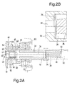
- the spring a diaphragm 34 is in its natural conical shape, as can be seen in the detail of figure 2B , leaving an adequate section for the passage of the oil.
- the oil thus continues on its path reaching the thrust chamber 64, after having crossed the longitudinal 36 and transversal 40 holes formed on the thrust shaft 18, the throat 60 and the hole 62 formed on the hub 54.
- the transversal hole 38 that intercepts the main longitudinal hole 36 on the thrust shaft 18 has multiple functions. In addition to ensuring the lubrication of the moving members of the clutch group 10, it has a precise calibration, with a lower passage section, based upon a predetermined ratio, with respect to that made by the valve with the Belleville spring 34. In this way, the flow rate of the oil, increasing with the revolutions of the engine up to a certain operating speed, does not create pressure because it flows out from the hole 38. As the flow rate of the oil increases, the pressure on the entire channelling up to the chamber 64 also increases, giving rise to an additional biasing on the plates 12 and 14 through the mobile equipment of the device, consisting of the hub 54 and the membrane 68 on whose surface the pressure of the oil acts. This generates an axial force that, through the bearing 22 and the relative containment ring 80, acts upon the thrust plate 24.
- the pressure of the oil shall gradually increase with the revolutions of the engine, until the pressure limitation valve 42 is made to open, as represented in figure 2A .
- the bowl 44 thrusted by the pressurised oil, pulls back compressing the inner spring 50, expels the air contained inside of it through the holes 48 until the holes 46, arranged downstream of the holes 48, are opened, through which the pressurised oil transits from the discharge port 56 to finally come out from the hole 58.
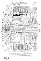
- Figure 4 represents the automatic control device according to the invention precisely in this condition, in other words when, with the manual control of the clutch 10 completely actuated, the hydraulic follow-up link is excluded.
- the clutch springs 16 are compressed by the thrust plate 24, the clutch plates 12 and 14 are free and the mobile wall with the membrane 68 connected to the hub 54 has moved towards the cover 72, reducing the volume of the oil chamber 64, which in the meantime has flowed out from the transversal hole 38 through the channels that will make the oil itself go back towards the chamber 64 when the control of the clutch 10 shall be released.
- the automatic device for controlling a clutch group integrated with a hydraulic follow-up link in addition to offering the advantage quoted above of being able to use a conventional clutch with a reduced spring biasing to cause the slipping of the plates 12 and 14, also makes it possible to have a biasing on the control that has never been above that of the springs 16 and, even during deceleration, in certain conditions, the biasing on the plates 12 and 14 increases through the follow-up link.
- the follow-up link can be excluded by acting just on the first portion of the manual control of the clutch, putting the drive wheel of the vehicle in bounce-prevention conditions.
- the biasing of the springs 16 on the plates 12 and 14 is not altered, with the advantage of making it easier to perform a possible bump start in an emergency. It is important to highlight that the device according to the invention can be applied without distinction to the type of control of the clutch, which can be either mechanical or hydraulic.
- the device described up to now is certainly valid to solve many of the behavioural problems that can emerge by using a clutch with conventional control, with a normal driving style, but it may not be sufficient to provide for the very advanced driving requirements linked with high-performance motorcycles.
- the motorcycle is used at its limit, in certain situations there is a need to achieve the bounce-prevention condition of the rear wheel before actuating the clutch control, for example when in full throttle the brake is actuated ahead of the clutch, causing a transfer of biasing onto the forecarriage and thus putting the rear drive wheel in critical grip conditions.
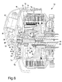
- Figure 6 shows an automatic device for controlling a clutch group integrated with an electronically managed hydraulic follow-up link to carry out the controlled slipping of the clutch plates. It should be specified that in this figure only the components that are added or modified compared to the basic version of the automatic control device, illustrated in the previous figures, are highlighted.
- All of the components that are actuated by the electronic management of the system are mounted in a suitable seat formed in the closing cover 72.
- the element that receives the control is a solenoid 82, represented in rest conditions with its own end 84 in contact with a rocker arm lever 86.
- the rocker arm lever 86 hinged on a pin 88 fixedly connected to the cover 72, transmits the movement to a barrel 90, free to slide axially in a seat 92 where a sealing element 94 is also housed.
- the barrel 90 due to the pressure in the chamber 64, maintains the contact with the end of the rocker arm lever 86.
- the automatic clutch control device integrated with a hydraulic follow-up link, to carry out the controlled sliding of the plates of the clutch of a vehicle, in particular a two-wheeled vehicle, according to the present invention achieves the purposes highlighted previously.
- the device according to the invention differs for the following details:
- such a device in its basic most cost-effective version, is suitable for being used on medium or medium-high performance vehicles, with suitable costs for this category of vehicles.
- the described device can on the other hand be implemented with the addition of the electronic management components, so as to make it sensitive to other parameters like for example the actuation of the front brake, particular biasing and engine revolution conditions, and yet more.
- the automatic clutch control device of the present invention thus conceived can in any case undergo numerous modifications and variants, all of which are covered by the same inventive concept; moreover, all of the details can be replaced by technically equivalent elements.
- the materials used, as well as the shapes and sizes, can be whatever according to the technical requirements.
Landscapes
- Engineering & Computer Science (AREA)
- General Engineering & Computer Science (AREA)
- Mechanical Engineering (AREA)
- Hydraulic Clutches, Magnetic Clutches, Fluid Clutches, And Fluid Joints (AREA)
Applications Claiming Priority (1)
| Application Number | Priority Date | Filing Date | Title |
|---|---|---|---|
| IT001071A ITMI20071071A1 (it) | 2007-05-25 | 2007-05-25 | Dispositivo automatico di comando di un gruppo frizione integrato con un asservimento idraulico per realizzare lo slittamento controllato dei dischi della frizione |
Publications (1)
| Publication Number | Publication Date |
|---|---|
| EP1995483A2 true EP1995483A2 (de) | 2008-11-26 |
Family
ID=39712394
Family Applications (1)
| Application Number | Title | Priority Date | Filing Date |
|---|---|---|---|
| EP08153769A Withdrawn EP1995483A2 (de) | 2007-05-25 | 2008-03-31 | Automatische Vorrichtung zur Steuerung einer Kupplungsgruppe mit einer hydraulischen Nachverfolgungsverbindung zur gesteuerten Verschiebung der Kupplungsscheiben |
Country Status (4)
| Country | Link |
|---|---|
| EP (1) | EP1995483A2 (de) |
| CN (1) | CN101311572A (de) |
| IT (1) | ITMI20071071A1 (de) |
| TW (1) | TW200905100A (de) |
Cited By (1)
| Publication number | Priority date | Publication date | Assignee | Title |
|---|---|---|---|---|
| TWI414697B (de) * | 2011-09-01 | 2013-11-11 |
Families Citing this family (4)
| Publication number | Priority date | Publication date | Assignee | Title |
|---|---|---|---|---|
| DE102011084584A1 (de) * | 2011-10-17 | 2013-04-18 | Zf Friedrichshafen Ag | Vorrichtung zur Steuerung eines Kühl- und/oder Schmierölstromes |
| CN104963959B (zh) * | 2015-07-13 | 2017-12-01 | 湖北奥德传动科技有限公司 | 一种活塞缸固定式的气压多片摩擦离合器 |
| GB2574263B (en) * | 2018-06-01 | 2020-09-30 | Caterpillar Sarl | Disconnect clutch |
| SE541427C2 (en) * | 2018-08-08 | 2019-10-01 | C Falk Remote Control Ab | Torque-limiting clutch comprising an electric control system |
-
2007
- 2007-05-25 IT IT001071A patent/ITMI20071071A1/it unknown
-
2008
- 2008-03-31 EP EP08153769A patent/EP1995483A2/de not_active Withdrawn
- 2008-05-22 TW TW097118883A patent/TW200905100A/zh unknown
- 2008-05-23 CN CNA2008101091801A patent/CN101311572A/zh active Pending
Non-Patent Citations (1)
| Title |
|---|
| None |
Cited By (1)
| Publication number | Priority date | Publication date | Assignee | Title |
|---|---|---|---|---|
| TWI414697B (de) * | 2011-09-01 | 2013-11-11 |
Also Published As
| Publication number | Publication date |
|---|---|
| CN101311572A (zh) | 2008-11-26 |
| ITMI20071071A1 (it) | 2008-11-26 |
| TW200905100A (en) | 2009-02-01 |
Similar Documents
| Publication | Publication Date | Title |
|---|---|---|
| US7546829B2 (en) | Straddle type vehicle | |
| EP1995483A2 (de) | Automatische Vorrichtung zur Steuerung einer Kupplungsgruppe mit einer hydraulischen Nachverfolgungsverbindung zur gesteuerten Verschiebung der Kupplungsscheiben | |
| EP2695781B1 (de) | Fahrzeug umfassend einen Fahrgeschwindigkeitsregler | |
| FR2496213A1 (fr) | Dispositif de controle de blocage pour un convertisseur de couple | |
| EP3225869B1 (de) | Hydraulikanlage | |
| EP3099961B1 (de) | Stufenloses getriebe und fahrzeugsteuerungsverfahren | |
| US20100089681A1 (en) | Friction clutch and vehicle equipped with the same | |
| EP2695783B1 (de) | Automatische Übertragungsvorrichtung und Sattelfahrzeug mit der Vorrichtung | |
| EP2696091A1 (de) | Sattelsitz-Fahrzeug | |
| US20120031086A1 (en) | Systems and methods for selectively disengaging a clutch to protect engines from damage | |
| US7753186B2 (en) | Vehicle clutch | |
| EP1961636A2 (de) | Hydraulischer Hauptzylinder und Fahrzeug damit | |
| US4792194A (en) | Antilock brake device for vehicles | |
| JPH07502328A (ja) | 乾式円板クラッチ誤用防止装置 | |
| JP7787731B2 (ja) | アクセルペダルの誤踏込防止装置、及び、アクセルペダルユニット | |
| FR2982925A1 (fr) | Clapet anti-retour tare a limiteur de couple a debit variable pour un element d'un circuit de commande par fluide | |
| JP2008157385A (ja) | バルブ装置 | |
| JPH0212288B2 (de) | ||
| KR200178178Y1 (ko) | 오토매틱 차량의 클러치 쇼크방지 밸브장치 | |
| JP6658218B2 (ja) | 蓄圧装置の開閉装置及び蓄圧装置 | |
| JPS6030434Y2 (ja) | エンジンの過回転防止装置 | |
| JPS5838185Y2 (ja) | デイ−ゼルエンジン車用自動変速機の制御装置 | |
| JP6173285B2 (ja) | 鞍乗り型車両の変速操作伝達装置及び変速機 | |
| FR2841617A1 (fr) | Systeme de pilotage d'un embrayage | |
| KR200146464Y1 (ko) | 자동차용 클러치 마스터 실린더 구조 |
Legal Events
| Date | Code | Title | Description |
|---|---|---|---|
| PUAI | Public reference made under article 153(3) epc to a published international application that has entered the european phase |
Free format text: ORIGINAL CODE: 0009012 |
|
| AK | Designated contracting states |
Kind code of ref document: A2 Designated state(s): AT BE BG CH CY CZ DE DK EE ES FI FR GB GR HR HU IE IS IT LI LT LU LV MC MT NL NO PL PT RO SE SI SK TR |
|
| AX | Request for extension of the european patent |
Extension state: AL BA MK RS |
|
| STAA | Information on the status of an ep patent application or granted ep patent |
Free format text: STATUS: THE APPLICATION IS DEEMED TO BE WITHDRAWN |
|
| 18D | Application deemed to be withdrawn |
Effective date: 20111004 |