EP1995432A1 - Moteur portable - Google Patents
Moteur portable Download PDFInfo
- Publication number
- EP1995432A1 EP1995432A1 EP07010129A EP07010129A EP1995432A1 EP 1995432 A1 EP1995432 A1 EP 1995432A1 EP 07010129 A EP07010129 A EP 07010129A EP 07010129 A EP07010129 A EP 07010129A EP 1995432 A1 EP1995432 A1 EP 1995432A1
- Authority
- EP
- European Patent Office
- Prior art keywords
- engine
- baffle plate
- convex rib
- engine casing
- casing
- Prior art date
- Legal status (The legal status is an assumption and is not a legal conclusion. Google has not performed a legal analysis and makes no representation as to the accuracy of the status listed.)
- Withdrawn
Links
Images


Classifications
-
- F—MECHANICAL ENGINEERING; LIGHTING; HEATING; WEAPONS; BLASTING
- F02—COMBUSTION ENGINES; HOT-GAS OR COMBUSTION-PRODUCT ENGINE PLANTS
- F02B—INTERNAL-COMBUSTION PISTON ENGINES; COMBUSTION ENGINES IN GENERAL
- F02B63/00—Adaptations of engines for driving pumps, hand-held tools or electric generators; Portable combinations of engines with engine-driven devices
- F02B63/04—Adaptations of engines for driving pumps, hand-held tools or electric generators; Portable combinations of engines with engine-driven devices for electric generators
-
- F—MECHANICAL ENGINEERING; LIGHTING; HEATING; WEAPONS; BLASTING
- F01—MACHINES OR ENGINES IN GENERAL; ENGINE PLANTS IN GENERAL; STEAM ENGINES
- F01P—COOLING OF MACHINES OR ENGINES IN GENERAL; COOLING OF INTERNAL-COMBUSTION ENGINES
- F01P1/00—Air cooling
- F01P2001/005—Cooling engine rooms
-
- F—MECHANICAL ENGINEERING; LIGHTING; HEATING; WEAPONS; BLASTING
- F01—MACHINES OR ENGINES IN GENERAL; ENGINE PLANTS IN GENERAL; STEAM ENGINES
- F01P—COOLING OF MACHINES OR ENGINES IN GENERAL; COOLING OF INTERNAL-COMBUSTION ENGINES
- F01P5/00—Pumping cooling-air or liquid coolants
- F01P5/02—Pumping cooling-air; Arrangements of cooling-air pumps, e.g. fans or blowers
- F01P5/06—Guiding or ducting air to, or from, ducted fans
-
- F—MECHANICAL ENGINEERING; LIGHTING; HEATING; WEAPONS; BLASTING
- F02—COMBUSTION ENGINES; HOT-GAS OR COMBUSTION-PRODUCT ENGINE PLANTS
- F02B—INTERNAL-COMBUSTION PISTON ENGINES; COMBUSTION ENGINES IN GENERAL
- F02B63/00—Adaptations of engines for driving pumps, hand-held tools or electric generators; Portable combinations of engines with engine-driven devices
- F02B63/04—Adaptations of engines for driving pumps, hand-held tools or electric generators; Portable combinations of engines with engine-driven devices for electric generators
- F02B63/044—Adaptations of engines for driving pumps, hand-held tools or electric generators; Portable combinations of engines with engine-driven devices for electric generators the engine-generator unit being placed on a frame or in an housing
- F02B63/048—Portable engine-generator combinations
Definitions
- the present invention relates to a portable engine.
- a traditional portable engine adopts a design of an integrated air duct, which cools inner parts with cooling air drawn in by a fan and then expels through a vent groove. In such a way, direction and flow of cooling air cannot be well controlled, the cylinder head cover cannot be well cooled, and it is possible to heat the low-temperature part of the casing with hot air at the cylinder head cover.
- a purpose of the present invention is to provide a portable engine, which has five air ducts and can specifically cool each part through controlling air intake of each air duct, thus attaining better cooling effect for the engine.
- a technical solution of the present invention is as follows: a portable engine, comprising an engine casing, an air deflector cover, a fan and an exhaust pipe; a left upper baffle plate and a right upper baffle plate at the upper part of the engine constitute two left and right upper air ducts together with a cylinder head cover and the engine casing; a left lower baffle plate and a right lower baffle plate at the lower part of the engine constitute two left and right lower air ducts together with the engine casing; and a base plate of the engine and the engine casing constitute a bottom air duct.
- a further technical solution of the present invention is as follows: a portable engine, comprising an engine casing, an air deflector cover, a fan and an exhaust pipe; a left upper baffle plate and a right upper baffle plate at the upper part of the engine constitute two left and right upper air ducts together with a cylinder head cover and the engine casing; a left lower baffle plate and a right lower baffle plate at the lower part of the engine constitute two left and right lower air ducts together with the engine casing; and a base plate of the engine and the engine casing constitute a bottom air duct.
- a left convex rib extends inward at the junction between the left upper baffle plate and the left lower baffle plate; a right convex rib extends inward at the junction between the right upper baffle plate and the right lower baffle plate;
- the left and right upper air ducts are composed of the left convex rib, the right convex rib, the cylinder head cover and the engine casing;
- an upper convex rib extends upward respectively on the left and right sides of the base plate of the engine;
- the bottom air duct is composed of the two upper convex ribs and the engine casing; and the left and right lower air ducts are composed of the left convex rib, the right convex rib, the upper convex rib and the engine casing.
- a portable engine comprising an engine casing, an air deflector cover, a fan and an exhaust pipe; a left upper baffle plate and a right upper baffle plate at the upper part of the engine constitute two left and right upper air ducts together with a cylinder head cover and the engine casing; a left lower baffle plate and a right lower baffle plate at the lower part of the engine constitute two left and right lower air ducts together with the engine casing; and a base plate of the engine and the engine casing constitute a bottom air duct.
- a left convex rib extends inward at the junction between the left upper baffle plate and the left lower baffle plate; a right convex rib extends inward at the junction between the right upper baffle plate and the right lower baffle plate;
- the left and right upper air ducts are composed of the left convex rib, the right convex rib, the cylinder head cover and the engine casing;
- an upper convex rib extends upward respectively on the left and right sides of the base plate of the engine;
- the bottom air duct is composed of the two upper convex ribs and the engine casing; and the left and right lower air ducts are composed of the left convex rib, the right convex rib, the upper convex rib and the engine casing.
- the two lower air ducts are provided at the end close to the fan respectively with an isolating plate, which is provided with several small vent holes and is on the engine casing.
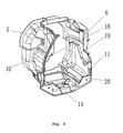
- a portable engine comprising an engine casing 1, an air deflector cover 2, a fan 3 and an exhaust pipe 4; a left convex rib 18 extends inward at the junction between the left upper baffle plate 5 and the left lower baffle plate 10 at the left part of the engine; a right convex rib 19 extends inward at the junction between the right upper baffle plate 6 and the right lower baffle plate 11 at the right part of the engine; a left convex rib 18 and a right convex rib 19 constitute two left and right upper air ducts 8 and 9 together with a cylinder head cover 7 and the engine casing 1; an upper convex rib 20 extends upward respectively on the left and right sides of the base plate of the engine; the bottom air duct 15 is composed of the two upper convex ribs 20 and the engine casing 1; the left convex rib 18 and the right convex rib 19 constitute two left and right lower air ducts together with the upper
- the two upper air ducts 8 and 9 cool the cylinder head directly.
- the two lower air ducts 12 and 13 can dissipate the heat produced by mechanical movements of the lower part of the engine during the engine operation and the heat conducted from the cylinder head.
- the bottom air duct 15 can cool the cooling fin at the bottom of the engine casing 1, and therefore can well lower temperature of the engine oil.
- the present invention can specifically cool each part through controlling air intake of each air duct, thus attaining better cooling effect for the engine.
Landscapes
- Engineering & Computer Science (AREA)
- Chemical & Material Sciences (AREA)
- Combustion & Propulsion (AREA)
- Mechanical Engineering (AREA)
- General Engineering & Computer Science (AREA)
- Cylinder Crankcases Of Internal Combustion Engines (AREA)
Priority Applications (1)
| Application Number | Priority Date | Filing Date | Title |
|---|---|---|---|
| EP07010129A EP1995432A1 (fr) | 2007-05-22 | 2007-05-22 | Moteur portable |
Applications Claiming Priority (1)
| Application Number | Priority Date | Filing Date | Title |
|---|---|---|---|
| EP07010129A EP1995432A1 (fr) | 2007-05-22 | 2007-05-22 | Moteur portable |
Publications (1)
| Publication Number | Publication Date |
|---|---|
| EP1995432A1 true EP1995432A1 (fr) | 2008-11-26 |
Family
ID=38659708
Family Applications (1)
| Application Number | Title | Priority Date | Filing Date |
|---|---|---|---|
| EP07010129A Withdrawn EP1995432A1 (fr) | 2007-05-22 | 2007-05-22 | Moteur portable |
Country Status (1)
| Country | Link |
|---|---|
| EP (1) | EP1995432A1 (fr) |
Cited By (4)
| Publication number | Priority date | Publication date | Assignee | Title |
|---|---|---|---|---|
| JP2014114769A (ja) * | 2012-12-11 | 2014-06-26 | Fuji Heavy Ind Ltd | アキシャルギャップ型発電体 |
| CN103967606A (zh) * | 2013-01-24 | 2014-08-06 | 曾礼 | 燃料气动马达 |
| CN108374713A (zh) * | 2017-02-01 | 2018-08-07 | Tvs电机股份有限公司 | 用于内燃发动机的冷却系统 |
| US12117213B1 (en) | 2018-11-19 | 2024-10-15 | Justin Schaefer | Portable internal combustion engine with heating and cooling capabilities |
Citations (6)
| Publication number | Priority date | Publication date | Assignee | Title |
|---|---|---|---|---|
| GB1247792A (en) * | 1968-01-27 | 1971-09-29 | Mosa S R L | Internal combustion engine driven electricity generating set |
| US5121715A (en) * | 1990-04-13 | 1992-06-16 | Yamaha Hatsudoki Kabushiki Kaisha | Compact power supply |
| US20020163196A1 (en) * | 2001-05-04 | 2002-11-07 | Brofft Roger W. | Power box |
| US20050046191A1 (en) * | 2003-08-28 | 2005-03-03 | Mainstream Engineering Corporation. | Lightweight portable electric generator |
| EP1645733A1 (fr) * | 2003-07-10 | 2006-04-12 | HONDA MOTOR CO., Ltd. | Generateur electrique entraine par un moteur |
| EP1707776A1 (fr) * | 2003-10-28 | 2006-10-04 | Henglin Xiao | Systeme de refroidissement pour moteur de generatrice |
-
2007
- 2007-05-22 EP EP07010129A patent/EP1995432A1/fr not_active Withdrawn
Patent Citations (6)
| Publication number | Priority date | Publication date | Assignee | Title |
|---|---|---|---|---|
| GB1247792A (en) * | 1968-01-27 | 1971-09-29 | Mosa S R L | Internal combustion engine driven electricity generating set |
| US5121715A (en) * | 1990-04-13 | 1992-06-16 | Yamaha Hatsudoki Kabushiki Kaisha | Compact power supply |
| US20020163196A1 (en) * | 2001-05-04 | 2002-11-07 | Brofft Roger W. | Power box |
| EP1645733A1 (fr) * | 2003-07-10 | 2006-04-12 | HONDA MOTOR CO., Ltd. | Generateur electrique entraine par un moteur |
| US20050046191A1 (en) * | 2003-08-28 | 2005-03-03 | Mainstream Engineering Corporation. | Lightweight portable electric generator |
| EP1707776A1 (fr) * | 2003-10-28 | 2006-10-04 | Henglin Xiao | Systeme de refroidissement pour moteur de generatrice |
Cited By (4)
| Publication number | Priority date | Publication date | Assignee | Title |
|---|---|---|---|---|
| JP2014114769A (ja) * | 2012-12-11 | 2014-06-26 | Fuji Heavy Ind Ltd | アキシャルギャップ型発電体 |
| CN103967606A (zh) * | 2013-01-24 | 2014-08-06 | 曾礼 | 燃料气动马达 |
| CN108374713A (zh) * | 2017-02-01 | 2018-08-07 | Tvs电机股份有限公司 | 用于内燃发动机的冷却系统 |
| US12117213B1 (en) | 2018-11-19 | 2024-10-15 | Justin Schaefer | Portable internal combustion engine with heating and cooling capabilities |
Similar Documents
| Publication | Publication Date | Title |
|---|---|---|
| CN203810348U (zh) | 舞台灯散热结构 | |
| CN201502430U (zh) | 汽油发电机的风道构造 | |
| CN101635486B (zh) | 一种用发动机驱动的发电机 | |
| EP1995432A1 (fr) | Moteur portable | |
| US7559297B2 (en) | Portable Engine | |
| CN209358383U (zh) | 一种变频发电机组的变频器安装及冷却结构 | |
| CN102809257A (zh) | 一种冷风型风冷油冷却器 | |
| CN210130047U (zh) | 后备箱散热装置 | |
| CN201742673U (zh) | 一种散热装置 | |
| CN109240472A (zh) | 一种带有散热风道结构的计算机主机箱 | |
| CN213016524U (zh) | 风冷柴油机导风装置 | |
| CN101640471B (zh) | 汽油发电机变频器外罩 | |
| CN214405981U (zh) | 灯体散热系统 | |
| CN109595066A (zh) | 自调节复合散热器 | |
| CN112412715A (zh) | 一种有效利用自然风的风力发电机组冷却方式 | |
| CN207264869U (zh) | 一种温控型变压器 | |
| CN207305252U (zh) | 一种提高散热效率的散热器结构 | |
| CN100482924C (zh) | 便携式发电机 | |
| CN207097378U (zh) | 一种可快速降温的led显示屏 | |
| CN217712742U (zh) | 一种发动机分层散热结构及发动机 | |
| CN110602863A (zh) | 电路板组件和具有其的电子设备 | |
| CN104167871A (zh) | 一种电机散热装置 | |
| CN212841463U (zh) | 一种导风式循环散热结构 | |
| CN211321200U (zh) | 小功率塑壳变频器的散热结构 | |
| CN211648325U (zh) | 强制风冷柴油机箱体 |
Legal Events
| Date | Code | Title | Description |
|---|---|---|---|
| PUAI | Public reference made under article 153(3) epc to a published international application that has entered the european phase |
Free format text: ORIGINAL CODE: 0009012 |
|
| 17P | Request for examination filed |
Effective date: 20070522 |
|
| AK | Designated contracting states |
Kind code of ref document: A1 Designated state(s): AT BE BG CH CY CZ DE DK EE ES FI FR GB GR HU IE IS IT LI LT LU LV MC MT NL PL PT RO SE SI SK TR |
|
| AX | Request for extension of the european patent |
Extension state: AL BA HR MK RS |
|
| AKX | Designation fees paid |
Designated state(s): AT BE BG CH CY CZ DE DK EE ES FI FR GB GR HU IE IS IT LI LT LU LV MC MT NL PL PT RO SE SI SK TR |
|
| STAA | Information on the status of an ep patent application or granted ep patent |
Free format text: STATUS: THE APPLICATION IS DEEMED TO BE WITHDRAWN |
|
| 18D | Application deemed to be withdrawn |
Effective date: 20121201 |