EP1994592B1 - Three-dimensional microbattery - Google Patents
Three-dimensional microbattery Download PDFInfo
- Publication number
- EP1994592B1 EP1994592B1 EP07706110A EP07706110A EP1994592B1 EP 1994592 B1 EP1994592 B1 EP 1994592B1 EP 07706110 A EP07706110 A EP 07706110A EP 07706110 A EP07706110 A EP 07706110A EP 1994592 B1 EP1994592 B1 EP 1994592B1
- Authority
- EP
- European Patent Office
- Prior art keywords
- substrate
- cavities
- layer
- electrode layer
- electrolyte
- Prior art date
- Legal status (The legal status is an assumption and is not a legal conclusion. Google has not performed a legal analysis and makes no representation as to the accuracy of the status listed.)
- Not-in-force
Links
- 239000000758 substrate Substances 0.000 abstract 3
- 239000003792 electrolyte Substances 0.000 abstract 2
- 238000004146 energy storage Methods 0.000 abstract 1
Images


Classifications
-
- H—ELECTRICITY
- H01—ELECTRIC ELEMENTS
- H01M—PROCESSES OR MEANS, e.g. BATTERIES, FOR THE DIRECT CONVERSION OF CHEMICAL ENERGY INTO ELECTRICAL ENERGY
- H01M6/00—Primary cells; Manufacture thereof
- H01M6/40—Printed batteries, e.g. thin film batteries
-
- H—ELECTRICITY
- H01—ELECTRIC ELEMENTS
- H01M—PROCESSES OR MEANS, e.g. BATTERIES, FOR THE DIRECT CONVERSION OF CHEMICAL ENERGY INTO ELECTRICAL ENERGY
- H01M10/00—Secondary cells; Manufacture thereof
- H01M10/04—Construction or manufacture in general
- H01M10/0436—Small-sized flat cells or batteries for portable equipment
-
- H—ELECTRICITY
- H01—ELECTRIC ELEMENTS
- H01M—PROCESSES OR MEANS, e.g. BATTERIES, FOR THE DIRECT CONVERSION OF CHEMICAL ENERGY INTO ELECTRICAL ENERGY
- H01M10/00—Secondary cells; Manufacture thereof
- H01M10/05—Accumulators with non-aqueous electrolyte
- H01M10/058—Construction or manufacture
-
- H—ELECTRICITY
- H01—ELECTRIC ELEMENTS
- H01M—PROCESSES OR MEANS, e.g. BATTERIES, FOR THE DIRECT CONVERSION OF CHEMICAL ENERGY INTO ELECTRICAL ENERGY
- H01M4/00—Electrodes
- H01M4/02—Electrodes composed of, or comprising, active material
- H01M4/04—Processes of manufacture in general
- H01M4/0402—Methods of deposition of the material
- H01M4/0421—Methods of deposition of the material involving vapour deposition
- H01M4/0428—Chemical vapour deposition
-
- H—ELECTRICITY
- H01—ELECTRIC ELEMENTS
- H01M—PROCESSES OR MEANS, e.g. BATTERIES, FOR THE DIRECT CONVERSION OF CHEMICAL ENERGY INTO ELECTRICAL ENERGY
- H01M10/00—Secondary cells; Manufacture thereof
- H01M10/05—Accumulators with non-aqueous electrolyte
- H01M10/052—Li-accumulators
- H01M10/0525—Rocking-chair batteries, i.e. batteries with lithium insertion or intercalation in both electrodes; Lithium-ion batteries
-
- Y—GENERAL TAGGING OF NEW TECHNOLOGICAL DEVELOPMENTS; GENERAL TAGGING OF CROSS-SECTIONAL TECHNOLOGIES SPANNING OVER SEVERAL SECTIONS OF THE IPC; TECHNICAL SUBJECTS COVERED BY FORMER USPC CROSS-REFERENCE ART COLLECTIONS [XRACs] AND DIGESTS
- Y02—TECHNOLOGIES OR APPLICATIONS FOR MITIGATION OR ADAPTATION AGAINST CLIMATE CHANGE
- Y02E—REDUCTION OF GREENHOUSE GAS [GHG] EMISSIONS, RELATED TO ENERGY GENERATION, TRANSMISSION OR DISTRIBUTION
- Y02E60/00—Enabling technologies; Technologies with a potential or indirect contribution to GHG emissions mitigation
- Y02E60/10—Energy storage using batteries
-
- Y—GENERAL TAGGING OF NEW TECHNOLOGICAL DEVELOPMENTS; GENERAL TAGGING OF CROSS-SECTIONAL TECHNOLOGIES SPANNING OVER SEVERAL SECTIONS OF THE IPC; TECHNICAL SUBJECTS COVERED BY FORMER USPC CROSS-REFERENCE ART COLLECTIONS [XRACs] AND DIGESTS
- Y02—TECHNOLOGIES OR APPLICATIONS FOR MITIGATION OR ADAPTATION AGAINST CLIMATE CHANGE
- Y02P—CLIMATE CHANGE MITIGATION TECHNOLOGIES IN THE PRODUCTION OR PROCESSING OF GOODS
- Y02P70/00—Climate change mitigation technologies in the production process for final industrial or consumer products
- Y02P70/50—Manufacturing or production processes characterised by the final manufactured product
-
- Y—GENERAL TAGGING OF NEW TECHNOLOGICAL DEVELOPMENTS; GENERAL TAGGING OF CROSS-SECTIONAL TECHNOLOGIES SPANNING OVER SEVERAL SECTIONS OF THE IPC; TECHNICAL SUBJECTS COVERED BY FORMER USPC CROSS-REFERENCE ART COLLECTIONS [XRACs] AND DIGESTS
- Y10—TECHNICAL SUBJECTS COVERED BY FORMER USPC
- Y10T—TECHNICAL SUBJECTS COVERED BY FORMER US CLASSIFICATION
- Y10T29/00—Metal working
- Y10T29/49—Method of mechanical manufacture
- Y10T29/49002—Electrical device making
- Y10T29/49108—Electric battery cell making
- Y10T29/49115—Electric battery cell making including coating or impregnating
Definitions
- Fig. 2 is a schematic, cutaway illustration of microbattery 10, in accordance with an embodiment of the present invention.
- a first current collector layer 24 is formed over the surface area of substrate 20.
- Layer 24 typically comprises a metallic layer, which is deposited over substrate 20 using any suitable thin-film deposition process known in the art.
- layer 24 forms a hollow structure or crust that coats the entire surface area , of the perforated substrate, both internally and externally to cavities 22.
- layer 24 coats the interior surfaces of cavities 22.
- Exemplary microbatteries in which layer 24 comprises a 2-4 micron nickel layer are described below. Alternatively, thinner (e.g., 1 micron) or thicker current collector layers can also be used.
- an electrolyte separator layer is applied over cathode layer 26 to form the separator layer of the microbattery, as is known in the art.
- the electrolyte separator layer comprises an ion-conducting electrolyte membrane 28.
- Membrane 28 is disposed so as to coat the cathode layer and fill the remaining interior volume of cavities 22.
- Membrane 28 extends beyond the outer surface (or surfaces) of substrate 20. Typically, such as in the example of Fig. 2 , the membrane extends beyond both opposite faces of the substrate and has two opposite planar outer surfaces.
- membrane 28 is in contact with cathode layer 26 across a large surface area, both in the interior of the cathode-plated cavities and over the external faces of the cathode-plated substrate.
- a second current collector layer 32 is optionally attached to the anode layer and connected to another terminal of battery 10.
- the anode comprises an electrically-conductive material (such as graphite)
- the second current collector may be omitted and the battery terminal connected directly to the anode.
- the anode and second current collector are substantially flat, 2-D layers that do not penetrate into cavities 22.
- terminal 34A and 34B are connected to the first and second current collector layers, respectively.
- Terminal 34A is led through a suitable opening in the microbattery structure and connected to layer 24.
- Terminal 34B is connected to layer 32.
- terminal 34A is connected directly to substrate 20.
- terminal 34B is connected directly to anode layer 30.
- microbattery 10 shown in Figs. 2 and 3 is simpler to fabricate. Because the anode layer is applied externally to the cavities, the ion-conducting membrane can be allowed to fill the entire remaining volume of the cavities, without the need to accommodate an additional anode layer. Thus, the membrane can be applied using various filling, pasting and/or casting methods, and not necessarily using conformal deposition processes. Moreover, the cathode layer can be made thicker, thus increasing the energy capacity of the battery.
- Fig. 4 is a flow chart that schematically illustrates a method for fabricating microbattery 10, in accordance with an embodiment of the present invention.
- the method begins by producing or otherwise obtaining a perforated substrate 20, at a substrate provisioning step 40.
- the perforated substrate may be produced as part of the microbattery fabrication process.
- a suitable perforated substrate may be provided a-priori.
- first current collector layer 24 is deposited on the substrate, at a first current collector forming step 42. Then, the first electrode layer (in the present example a cathode layer) is formed, coating the first current collector layer, at a first electrode forming step 44. When the first current collector is omitted, the first electrode layer coats the substrate.
- Membrane 28 is then applied, at a membrane forming step 46.
- the membrane material fills the remaining volume of cavities 22 and extends beyond the 3-D structure of the substrate, forming one or two outer surfaces.
- a second electrode layer (in the present example an anode layer) is then applied to at least one of the outer surfaces of the membrane, at a second electrode forming step 48.
- second current collector layer 32 is applied to the anode layer, at a second current collector forming step 50. Terminals can then be connected to the microbattery, and the assembled microbattery can be packaged and/or sealed using any suitable means.
- An electroless method known in the art to provide conformal coating, is used to deposit the nickel current collector on all exposed surfaces of the MCP substrate.
- the electroless deposition of nickel comprises several sequential repetitions of sensitization in a SnCl 2 , HCl:H 2 O solution, activation in a PdCl 2 , HCl:H 2 O solution and nickel reduction.
- the activated nickel-plated substrate is immersed in an alkaline Ni-electroless bath with trisoduim citrate as a complexant and sodium hypophosphite as a reduction component.
- the autocatalytic process is carried out at 65-70°C for 5-15 minutes.
- the thickness of the deposited nickel layer varies according to the deposition time. For example, 15 minutes of deposition produce a layer thickness of approximately 2 microns.
- the composition of the electroless solution is as follows: nickel sulfamate: 0.100M, sodium citrate: 0.125M, sodium acetate: 0.100M, sodium hypophosphite: 0.314M, thiourea: 0.1md/L, sodium dodecylsulfate: 10mg/L, pH: 9.
- the resulting current collector layer is conformal and highly adherent, completely coating the cavities.
- the electroless process described above yields a uniform 2-4 micron nickel layer both inside the cavities and on the external faces of the substrate.
- the nickel-plated substrate is washed with deionized water and then subjected to electrochemical cathode deposition.
- the electrochemical deposition process is carried out in an electrolytic bath comprising tetrathiomolybdate MoS 4 2 - anions as the electroactive species.
- the bath is prepared by mixing aqueous solutions of Na 2 S and Na 2 MoO 4 and adjusting the pH of the solution to a value in the range 7.5-8.0 by adding HCl or KH 2 PO 4 .
- the HPE ion-conducting membrane comprises a commercially available PVDF-2801 copolymer (Kynar).
- SiO 2 Adrich 130
- DMSO high-purity cyclopentanone
- Fumed silica 130 Degussa
- PC propylene carbonate
- PEGDME can be used as a pore former.
- the thickness of the membrane and its morphology depends on the amount of solids in the casting slurry and on the type of solvent and pore former used.
- the membrane slurry is inserted into the cavities using several sequential spin-coating and vacuum pulling steps.
- the LiC 6-x /BPE/MoS 2 cells were cycled at room temperature using a Maccor series 2000 battery test system.
- the voltage cut-off was in the range of 1.3-2.4V.
- the charge/discharge current density was 10 ⁇ A/cm 2 .
- the cell delivered a capacity of 1.5 mAh/cm 2 per cycle for over 100 reversible cycles, with a capacity fading rate of 0,05%/cycle.
- the Faradaic efficiency was close to 100%.
- Fig. 5 is a graph showing a comparison between reversible capacities of 2-D and 3-D microbatteries having composite and pristine cathodes, in accordance with embodiments of the present invention.
- the graph shows the capacity (energy density in mAh/cm 2 ) as a function of the number of cycles for several exemplary microbatteries.
- the current density used in the cathode deposition is doubled.
- the cathode deposition time also increases, typically from 0.5 to 2 hours.
- Composite cathode films are highly adherent to the substrate.
- Data points 62 show the capacity of a 2-D thin-film battery having a pristine cathode and the same footprint as the 3-D microbatteries described above.
- Data points 66 show the capacity of a comparable 2-D battery having a composite cathode. As can be seen in the figure, the capacity of a 3-D microbattery is an order of magnitude larger than the capacity of a comparable 2-D battery.
- a 3-D microbattery is assembled similarly to example 2.
- the composite cathode is deposited using an electrolyte having a 1:6 polymer-to-salt ratio at a current density of 20 mA/cm 2 for one hour.
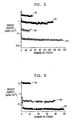
- Fig. 6 is a graph showing a comparison between reversible capacities of 2-D and 3-D microbatteries having composite and pristine cathodes, in accordance with embodiments of the present invention.
- Data points 62 and 66 show the capacities of 2-D batteries having pristine and composite cathodes, respectively.
- Data points 70 show the capacity of the 3-D microbattery of example 3, whose composite cathode is deposited using an electrolyte having a 1:6 polymer-to-salt ratio.
- the reversible discharge capacity of the 3-D microbattery approaches 10mAh/cm 2 , almost two orders of magnitude larger than the capacity of a comparable 2-D battery.
- a 3-D microbattery is assembled similarly to examples 1 and 2.
- the HPE membrane is cast only on one surface of the substrate.
- the resulting microbattery runs over 40 reversible cycles with a capacity loss of less than 0.1%/cycle. This example applies to both pristine and composite cathodes.
- a 3-D microbattery is assembled similarly to examples 1 and 2, with the HPE membrane cast on both surfaces of the MCP substrate.
- the cathode in this example comprises a composite cathode.
- the microbattery has a reversible capacity of approximately 5mAh/cm 2 at room temperature.
- an additional 10 micron layer of LiBF 4 :P(EO) 20 polymer electrolyte can be applied by spin-coating to the two external faces of the MCP substrate, after the substrate had been coated with the nickel current collector and molybdenum oxysulfide cathode.
- Poly(ethylene oxide) (P(EO)) Aldrich, average molecular weight 5x10 6 ) is vacuum-dried at 45-50°C for approximately 24 hours.
- a polymer slurry is prepared by dispersing known quantities of P(EO) and LiBF 4 , in analytical grade acetonitrile, together with the required amount of an inorganic filler, such as Al 2 O 3 (Buehler) having an average diameter of approximately 150 ⁇ .
- an ultrasonic bath or high-speed homogenizer can be used. The suspension is stirred for approximately 24 hours before the PE films are cast on the fine polished Teflon support (having a 64 cm 2 area). The solvent is allowed to evaporate slowly. The final thickness of the solvent-free PE films is in the range of 10-15 microns.
- PVDF-SiO 2 membrane insertion is carried out using a casting process and vacuum filling steps as in example 1 above.
- the degree of capacity degradation does not exceed 0.5%/cycle (100% DOD) when the Li/PEO-PVDF)/MoO x S y battery is cycled at a current density of 40 ⁇ A/cm 2 and a voltage cutoff in the range of 1.3-2.2V.
- a 3-D microbattery is assembled similarly to examples 1, 2 or 4.
- a Celgard 2400 separator is used as a polymer membrane.
- the resulting voltage cutoff is in the range of 1.3-2.4V.
- the charge/discharge current density is 40 ⁇ A/cm 2 .
- the battery delivers a capacity of 4.5mAh per cycle for over than 20 reversible cycles with a capacity fading rate of 0.06%/cycle.
- the Faradaic efficiency is close to 100%.
- a 3-D microbattery is assembled on a silicon substrate.
- the battery comprises a lithium-ion anode, HPE membrane and a MoS 2 cathode.
- the silicon substrate is immersed in an acetone and weak base solution for 5 minutes, and then washed in deionized water with successive immersion into a H 2 O 2 :HCl mixture for another 5 minutes. After rinsing in deinozed water, the substrate is etched in a NH 4 F:HF solution for 2 minutes, in order to roughen the silicon surface to increase the adherence of the current collector to the surface.
- Molybdenum oxysulfide is deposited on the substrate similarly to example 2 above.
- a commercially available PVDF-2801 copolymer (Kynar) is used as a binder, and fumed silica is used as filler for the polymer membrane.
- the battery is charged by a liquid Lilmide-ethylene carbonate (EC):dimethyl carbonate (DMC) 1:1 (v/v) electrolyte.
- EC liquid Lilmide-ethylene carbonate
- DMC dimethyl carbonate
- the resulting 3-D lithium-ion/hybrid polymer electrolyte/MoS 2 battery is cycled at room temperature using a Maccor series 2000 battery test system:
- the voltage cut-off is in the range of 1.2-2.3V.
- the charge/discharge current density is in the range of 10-100 ⁇ A/cm 2 .
- the battery delivers a capacity of over 2mAh per cycle at 40 ⁇ A/cm 2 for over 30 reversible cycles, with a capacity fading rate of 0.1%/cycle.
- the Faradaic efficiency is close to 100%.
- the retained graphite flakes are filtered and washed with dry hexane. Distilled water is added slowly to the solution. A known volume of LiOH (in aqueous phase) is titrated with HCL. The calculated number of moles of LiOH is subtracted from the initial number moles of Li-NM, to give the actual number of moles of lithium intercalated.
- the electrolyte for copper electrodeposition contains (g/L): 200-250 CuSO 4 x5H 2 O and 50-60 H 2 SO 4 .
- the electrodeposition is performed at room temperature and a current density of 50 mA/cm 2 for 8 minutes.
- the copper layer is electro-oxidized in an aqueous solution of polysulfides (a mixture of 10mM Na 2 S, 0.1M NaOH and elemental sulfur) at a constant current of 0.1-0.5mA/cm 2 for several seconds.
- the degree of capacity degradation of the resulting lithium-ion/HPE/Cu 2 S microbattery does not exceed 1.5%/cycle.
- the principles of the present invention can also be used to fabricate other energy storage devices, such as double-layer capacitors (DLC) and other capacitor types.
- DLC double-layer capacitors
Landscapes
- Engineering & Computer Science (AREA)
- Manufacturing & Machinery (AREA)
- Chemical & Material Sciences (AREA)
- Chemical Kinetics & Catalysis (AREA)
- Electrochemistry (AREA)
- General Chemical & Material Sciences (AREA)
- Secondary Cells (AREA)
- Battery Electrode And Active Subsutance (AREA)
- Electric Double-Layer Capacitors Or The Like (AREA)
- Cell Electrode Carriers And Collectors (AREA)
- Steroid Compounds (AREA)
- Transition And Organic Metals Composition Catalysts For Addition Polymerization (AREA)
- Cell Separators (AREA)
Applications Claiming Priority (2)
| Application Number | Priority Date | Filing Date | Title |
|---|---|---|---|
| US11/374,469 US7618748B2 (en) | 2006-03-13 | 2006-03-13 | Three-dimensional microbattery |
| PCT/IL2007/000167 WO2007105196A1 (en) | 2006-03-13 | 2007-02-07 | Three-dimensional microbattery |
Publications (2)
| Publication Number | Publication Date |
|---|---|
| EP1994592A1 EP1994592A1 (en) | 2008-11-26 |
| EP1994592B1 true EP1994592B1 (en) | 2010-07-14 |
Family
ID=38189170
Family Applications (1)
| Application Number | Title | Priority Date | Filing Date |
|---|---|---|---|
| EP07706110A Not-in-force EP1994592B1 (en) | 2006-03-13 | 2007-02-07 | Three-dimensional microbattery |
Country Status (7)
| Country | Link |
|---|---|
| US (1) | US7618748B2 (enExample) |
| EP (1) | EP1994592B1 (enExample) |
| JP (1) | JP4555378B2 (enExample) |
| CN (1) | CN101401238B (enExample) |
| AT (1) | ATE474337T1 (enExample) |
| DE (1) | DE602007007736D1 (enExample) |
| WO (1) | WO2007105196A1 (enExample) |
Families Citing this family (42)
| Publication number | Priority date | Publication date | Assignee | Title |
|---|---|---|---|---|
| WO2004036668A2 (en) * | 2002-10-17 | 2004-04-29 | Tel-Aviv University Future Technology Development L.P. | Thin-film cathode for 3-dimensional microbattery and method for preparing such cathode |
| US7557433B2 (en) | 2004-10-25 | 2009-07-07 | Mccain Joseph H | Microelectronic device with integrated energy source |
| FR2901639B1 (fr) * | 2006-05-24 | 2008-08-22 | Commissariat Energie Atomique | Micro-composant integre associant les fonctions de recuperation et de stockage de l'energie |
| FR2910721B1 (fr) * | 2006-12-21 | 2009-03-27 | Commissariat Energie Atomique | Ensemble collecteur de courant-electrode avec des cavites d'expansion pour accumulateur au lithium sous forme de films minces. |
| US8740873B2 (en) * | 2007-03-15 | 2014-06-03 | Hologic, Inc. | Soft body catheter with low friction lumen |
| WO2010007579A1 (en) | 2008-07-14 | 2010-01-21 | Nxp B.V. | Three-dimensional solid state battery |
| US7875382B2 (en) * | 2008-08-28 | 2011-01-25 | International Battery, Inc. | Battery |
| US7855011B2 (en) | 2008-08-28 | 2010-12-21 | International Battery, Inc. | Monoblock lithium ion battery |
| US8329327B2 (en) * | 2009-05-08 | 2012-12-11 | Robert Bosch Gmbh | Li-ion battery with variable volume reservoir |
| US20110045351A1 (en) * | 2009-08-23 | 2011-02-24 | Ramot At Tel-Aviv University Ltd. | High-Power Nanoscale Cathodes for Thin-Film Microbatteries |
| JP5458172B2 (ja) | 2010-02-01 | 2014-04-02 | エルジー・ケム・リミテッド | ケーブル型二次電池 |
| KR101279409B1 (ko) * | 2010-02-01 | 2013-06-27 | 주식회사 엘지화학 | 케이블형 이차전지 |
| WO2011154862A1 (en) | 2010-06-06 | 2011-12-15 | Ramot At Tel-Aviv University Ltd | Three-dimensional microbattery having a porous silicon anode |
| KR101861212B1 (ko) * | 2010-09-09 | 2018-06-29 | 캘리포니아 인스티튜트 오브 테크놀로지 | 전기화학적 에너지 저장 시스템 및 방법 |
| US9249522B2 (en) | 2010-12-05 | 2016-02-02 | Ramot At Tel-Aviv University Ltd. | Electrophoretic deposition of thin film batteries |
| EP2732487A4 (en) | 2011-07-11 | 2015-04-08 | California Inst Of Techn | NEW SEPARATORS FOR ELECTROCHEMICAL SYSTEMS |
| US9379368B2 (en) | 2011-07-11 | 2016-06-28 | California Institute Of Technology | Electrochemical systems with electronically conductive layers |
| US8785034B2 (en) * | 2011-11-21 | 2014-07-22 | Infineon Technologies Austria Ag | Lithium battery, method for manufacturing a lithium battery, integrated circuit and method of manufacturing an integrated circuit |
| DE102012200862A1 (de) * | 2012-01-23 | 2013-07-25 | Robert Bosch Gmbh | Batterie-Herstellung mittels Spincoating |
| WO2014028853A1 (en) * | 2012-08-16 | 2014-02-20 | The Regents Of The University Of California | Thin film electrolyte based 3d micro-batteries |
| JP6475627B2 (ja) * | 2012-10-19 | 2019-02-27 | コロラド ステート ユニバーシティー リサーチ ファウンデーション | 電極材料上へのコーティングの電解重合 |
| DE102013104148A1 (de) | 2013-04-24 | 2014-10-30 | Infineon Technologies Ag | Funkkommunikationsprozessoranordnung |
| US20140370189A1 (en) * | 2013-06-13 | 2014-12-18 | Xuesong Li | Method for synthesis of Graphene Films With Large Area and High Throughput |
| US10714724B2 (en) | 2013-11-18 | 2020-07-14 | California Institute Of Technology | Membranes for electrochemical cells |
| WO2015074037A2 (en) | 2013-11-18 | 2015-05-21 | California Institute Of Technology | Separator enclosures for electrodes and electrochemical cells |
| CN104821414A (zh) * | 2014-01-30 | 2015-08-05 | 纳米及先进材料研发院有限公司 | 透明或半透明电池制造方法 |
| US20160064769A1 (en) * | 2014-08-29 | 2016-03-03 | Kobi Goldstein | System for fabricating an electrical storage cell |
| EP3204971A4 (en) * | 2014-10-08 | 2018-10-24 | Wayne State University | Electrocatalysis of lithium polysulfides: current collectors as electrodes in li/s battery configuration |
| WO2016141027A2 (en) * | 2015-03-02 | 2016-09-09 | The Regents Of The University Of California | Microbattery |
| WO2017055984A1 (en) | 2015-09-30 | 2017-04-06 | Ramot At Tel Aviv University Ltd. | 3d micro-battery on 3d-printed substrate |
| US10340528B2 (en) | 2015-12-02 | 2019-07-02 | California Institute Of Technology | Three-dimensional ion transport networks and current collectors for electrochemical cells |
| EP3602655A4 (en) * | 2017-03-20 | 2020-12-23 | Millibatt, Inc. | BATTERY SYSTEM AND MANUFACTURING PROCESS |
| US10615417B2 (en) | 2017-05-15 | 2020-04-07 | Millibatt, Inc. | Electrolyte material, battery assembly, and production method |
| CN108063219B (zh) * | 2017-11-23 | 2020-01-10 | 浙江大学 | 一种高效液态碱金属合金电极及其制备方法和应用 |
| US11245134B2 (en) | 2019-01-02 | 2022-02-08 | International Business Machines Corporation | Lithium energy storage device with composite anode |
| US12170353B2 (en) | 2019-01-02 | 2024-12-17 | International Business Machines Corporation | Method of making a lithium energy storage device |
| US11862983B1 (en) | 2019-03-28 | 2024-01-02 | Roger W. Graham | Earth energy systems and devices |
| WO2021183394A1 (en) * | 2020-03-07 | 2021-09-16 | Slobodan Petrovic | Inserted cavity electrode lithium battery |
| CN111613772B (zh) * | 2020-04-21 | 2022-08-05 | 浙江锋锂新能源科技有限公司 | 一种三维结构复合金属锂负极及其制备方法 |
| CN111863582B (zh) * | 2020-07-24 | 2022-04-22 | 北方夜视技术股份有限公司 | 超声悬浮旋转式微通道板腐蚀方法 |
| EP4193400A4 (en) * | 2020-08-19 | 2024-10-23 | Millibatt, Inc. | THREE-DIMENSIONAL FOLDED BATTERY UNIT AND METHODS OF MANUFACTURING THE SAME |
| KR102546090B1 (ko) * | 2023-03-15 | 2023-06-21 | 이운경 | 다층박막 기반의 전자소자 및 3차원 구조체를 이용한 그의 제조방법 |
Family Cites Families (19)
| Publication number | Priority date | Publication date | Assignee | Title |
|---|---|---|---|---|
| FR2550015B3 (fr) | 1983-07-28 | 1986-03-21 | Rech Applic Electrochimique | Generateur electrochimique en couche mince comportant une electrode positive electrodeposee |
| DE3838329A1 (de) * | 1987-11-11 | 1989-05-24 | Ricoh Kk | Negative elektrode fuer sekundaerbatterie |
| US5041199A (en) | 1990-04-04 | 1991-08-20 | Gould Inc. | Process for producing electrodeposited electrodes for use in electrochemical cells |
| US5338625A (en) * | 1992-07-29 | 1994-08-16 | Martin Marietta Energy Systems, Inc. | Thin film battery and method for making same |
| DE4317623C2 (de) * | 1993-05-27 | 2003-08-21 | Bosch Gmbh Robert | Verfahren und Vorrichtung zum anisotropen Plasmaätzen von Substraten und dessen Verwendung |
| JPH07263028A (ja) * | 1994-03-25 | 1995-10-13 | Fuji Photo Film Co Ltd | 非水二次電池 |
| DE19706682C2 (de) * | 1997-02-20 | 1999-01-14 | Bosch Gmbh Robert | Anisotropes fluorbasiertes Plasmaätzverfahren für Silizium |
| DE19734278C1 (de) * | 1997-08-07 | 1999-02-25 | Bosch Gmbh Robert | Vorrichtung zum anisotropen Ätzen von Substraten |
| US6066020A (en) * | 1997-08-08 | 2000-05-23 | Itt Manufacturing Enterprises, Inc. | Microchannel plates (MCPS) having micron and submicron apertures |
| IL123462A0 (en) * | 1998-02-26 | 1998-09-24 | Carbon Membranes Ltd | A method for potting or casting inorganic hollow fiber membranes intotube sheets |
| EP1119523B1 (en) * | 1998-07-30 | 2010-11-10 | Corning Incorporated | Method of fabricating photonic structures |
| US6197450B1 (en) * | 1998-10-22 | 2001-03-06 | Ramot University Authority For Applied Research & Industrial Development Ltd. | Micro electrochemical energy storage cells |
| JP3353070B2 (ja) | 2000-03-17 | 2002-12-03 | 東京工業大学長 | 薄膜形成方法 |
| WO2002009212A1 (en) * | 2000-07-24 | 2002-01-31 | Microcell Corporation | Microcell electrochemical devices and assemblies, and method of making and using the same |
| US7204862B1 (en) * | 2002-01-10 | 2007-04-17 | Excellatron Solid State, Llc | Packaged thin film batteries and methods of packaging thin film batteries |
| JP2007506226A (ja) | 2003-09-15 | 2007-03-15 | コニンクリユケ フィリップス エレクトロニクス エヌ.ブイ. | 電気化学エネルギー源、電子装置及び同エネルギー源の製造方法 |
| WO2005036711A2 (en) | 2003-10-14 | 2005-04-21 | Tel Aviv University Future Technology Development L.P. | Three-dimensional thin-film microbattery |
| US8187740B2 (en) | 2004-04-27 | 2012-05-29 | Tel Aviv University Future Technology Development L.P. | 3-D microbatteries based on interlaced micro-container structures |
| JP5181413B2 (ja) * | 2005-09-13 | 2013-04-10 | 日立電線株式会社 | 電気化学装置用電極、固体電解質/電極接合体及びその製造方法 |
-
2006
- 2006-03-13 US US11/374,469 patent/US7618748B2/en not_active Expired - Fee Related
-
2007
- 2007-02-07 DE DE602007007736T patent/DE602007007736D1/de active Active
- 2007-02-07 AT AT07706110T patent/ATE474337T1/de not_active IP Right Cessation
- 2007-02-07 EP EP07706110A patent/EP1994592B1/en not_active Not-in-force
- 2007-02-07 CN CN200780008458XA patent/CN101401238B/zh not_active Expired - Fee Related
- 2007-02-07 WO PCT/IL2007/000167 patent/WO2007105196A1/en not_active Ceased
- 2007-02-07 JP JP2008558976A patent/JP4555378B2/ja not_active Expired - Fee Related
Also Published As
| Publication number | Publication date |
|---|---|
| ATE474337T1 (de) | 2010-07-15 |
| CN101401238B (zh) | 2010-09-01 |
| JP4555378B2 (ja) | 2010-09-29 |
| US7618748B2 (en) | 2009-11-17 |
| JP2009530765A (ja) | 2009-08-27 |
| CN101401238A (zh) | 2009-04-01 |
| DE602007007736D1 (de) | 2010-08-26 |
| WO2007105196A1 (en) | 2007-09-20 |
| EP1994592A1 (en) | 2008-11-26 |
| US20070212603A1 (en) | 2007-09-13 |
Similar Documents
| Publication | Publication Date | Title |
|---|---|---|
| EP1994592B1 (en) | Three-dimensional microbattery | |
| US10403884B2 (en) | Electrode structures | |
| CN100508260C (zh) | 电能储存器件及其制造方法 | |
| CN107104243B (zh) | 用于能量存储装置的离子透过结构 | |
| TWI745651B (zh) | 用於三維電池之分離器 | |
| CN102812579B (zh) | 微电池及其制造方法 | |
| US20060032046A1 (en) | Thin-film cathode for 3-dimensional microbattery and method for preparing such cathode | |
| WO2017055984A1 (en) | 3d micro-battery on 3d-printed substrate | |
| KR20130012008A (ko) | 전지용 음극 전구체 재료의 제조 방법, 전지용 음극 전구체 재료 및 전지 | |
| CN106063007B (zh) | 具有非晶态合金制成的收集极的阳极室 | |
| US20230035022A1 (en) | A novel gold-based porous material for a lithium battery | |
| JP7847593B2 (ja) | 電極として使用するためのコーティングされた3次元電子伝導性ネットワーク | |
| US20240363831A1 (en) | Lithium rechargeable batteries | |
| HK1202988B (en) | Microstructured electrode structures |
Legal Events
| Date | Code | Title | Description |
|---|---|---|---|
| PUAI | Public reference made under article 153(3) epc to a published international application that has entered the european phase |
Free format text: ORIGINAL CODE: 0009012 |
|
| 17P | Request for examination filed |
Effective date: 20080729 |
|
| AK | Designated contracting states |
Kind code of ref document: A1 Designated state(s): AT BE BG CH CY CZ DE DK EE ES FI FR GB GR HU IE IS IT LI LT LU LV MC NL PL PT RO SE SI SK TR |
|
| GRAP | Despatch of communication of intention to grant a patent |
Free format text: ORIGINAL CODE: EPIDOSNIGR1 |
|
| DAX | Request for extension of the european patent (deleted) | ||
| GRAS | Grant fee paid |
Free format text: ORIGINAL CODE: EPIDOSNIGR3 |
|
| GRAA | (expected) grant |
Free format text: ORIGINAL CODE: 0009210 |
|
| AK | Designated contracting states |
Kind code of ref document: B1 Designated state(s): AT BE BG CH CY CZ DE DK EE ES FI FR GB GR HU IE IS IT LI LT LU LV MC NL PL PT RO SE SI SK TR |
|
| REG | Reference to a national code |
Ref country code: GB Ref legal event code: FG4D |
|
| REG | Reference to a national code |
Ref country code: CH Ref legal event code: EP |
|
| REG | Reference to a national code |
Ref country code: IE Ref legal event code: FG4D |
|
| REF | Corresponds to: |
Ref document number: 602007007736 Country of ref document: DE Date of ref document: 20100826 Kind code of ref document: P |
|
| REG | Reference to a national code |
Ref country code: NL Ref legal event code: VDEP Effective date: 20100714 |
|
| LTIE | Lt: invalidation of european patent or patent extension |
Effective date: 20100714 |
|
| PG25 | Lapsed in a contracting state [announced via postgrant information from national office to epo] |
Ref country code: LT Free format text: LAPSE BECAUSE OF FAILURE TO SUBMIT A TRANSLATION OF THE DESCRIPTION OR TO PAY THE FEE WITHIN THE PRESCRIBED TIME-LIMIT Effective date: 20100714 Ref country code: NL Free format text: LAPSE BECAUSE OF FAILURE TO SUBMIT A TRANSLATION OF THE DESCRIPTION OR TO PAY THE FEE WITHIN THE PRESCRIBED TIME-LIMIT Effective date: 20100714 Ref country code: AT Free format text: LAPSE BECAUSE OF FAILURE TO SUBMIT A TRANSLATION OF THE DESCRIPTION OR TO PAY THE FEE WITHIN THE PRESCRIBED TIME-LIMIT Effective date: 20100714 Ref country code: FI Free format text: LAPSE BECAUSE OF FAILURE TO SUBMIT A TRANSLATION OF THE DESCRIPTION OR TO PAY THE FEE WITHIN THE PRESCRIBED TIME-LIMIT Effective date: 20100714 |
|
| PG25 | Lapsed in a contracting state [announced via postgrant information from national office to epo] |
Ref country code: PL Free format text: LAPSE BECAUSE OF FAILURE TO SUBMIT A TRANSLATION OF THE DESCRIPTION OR TO PAY THE FEE WITHIN THE PRESCRIBED TIME-LIMIT Effective date: 20100714 Ref country code: SI Free format text: LAPSE BECAUSE OF FAILURE TO SUBMIT A TRANSLATION OF THE DESCRIPTION OR TO PAY THE FEE WITHIN THE PRESCRIBED TIME-LIMIT Effective date: 20100714 Ref country code: PT Free format text: LAPSE BECAUSE OF FAILURE TO SUBMIT A TRANSLATION OF THE DESCRIPTION OR TO PAY THE FEE WITHIN THE PRESCRIBED TIME-LIMIT Effective date: 20101115 Ref country code: CY Free format text: LAPSE BECAUSE OF FAILURE TO SUBMIT A TRANSLATION OF THE DESCRIPTION OR TO PAY THE FEE WITHIN THE PRESCRIBED TIME-LIMIT Effective date: 20100714 Ref country code: BG Free format text: LAPSE BECAUSE OF FAILURE TO SUBMIT A TRANSLATION OF THE DESCRIPTION OR TO PAY THE FEE WITHIN THE PRESCRIBED TIME-LIMIT Effective date: 20101014 Ref country code: IS Free format text: LAPSE BECAUSE OF FAILURE TO SUBMIT A TRANSLATION OF THE DESCRIPTION OR TO PAY THE FEE WITHIN THE PRESCRIBED TIME-LIMIT Effective date: 20101114 |
|
| PG25 | Lapsed in a contracting state [announced via postgrant information from national office to epo] |
Ref country code: SE Free format text: LAPSE BECAUSE OF FAILURE TO SUBMIT A TRANSLATION OF THE DESCRIPTION OR TO PAY THE FEE WITHIN THE PRESCRIBED TIME-LIMIT Effective date: 20100714 Ref country code: BE Free format text: LAPSE BECAUSE OF FAILURE TO SUBMIT A TRANSLATION OF THE DESCRIPTION OR TO PAY THE FEE WITHIN THE PRESCRIBED TIME-LIMIT Effective date: 20100714 Ref country code: LV Free format text: LAPSE BECAUSE OF FAILURE TO SUBMIT A TRANSLATION OF THE DESCRIPTION OR TO PAY THE FEE WITHIN THE PRESCRIBED TIME-LIMIT Effective date: 20100714 Ref country code: GR Free format text: LAPSE BECAUSE OF FAILURE TO SUBMIT A TRANSLATION OF THE DESCRIPTION OR TO PAY THE FEE WITHIN THE PRESCRIBED TIME-LIMIT Effective date: 20101015 |
|
| PG25 | Lapsed in a contracting state [announced via postgrant information from national office to epo] |
Ref country code: DK Free format text: LAPSE BECAUSE OF FAILURE TO SUBMIT A TRANSLATION OF THE DESCRIPTION OR TO PAY THE FEE WITHIN THE PRESCRIBED TIME-LIMIT Effective date: 20100714 |
|
| PLBE | No opposition filed within time limit |
Free format text: ORIGINAL CODE: 0009261 |
|
| STAA | Information on the status of an ep patent application or granted ep patent |
Free format text: STATUS: NO OPPOSITION FILED WITHIN TIME LIMIT |
|
| PG25 | Lapsed in a contracting state [announced via postgrant information from national office to epo] |
Ref country code: IT Free format text: LAPSE BECAUSE OF FAILURE TO SUBMIT A TRANSLATION OF THE DESCRIPTION OR TO PAY THE FEE WITHIN THE PRESCRIBED TIME-LIMIT Effective date: 20100714 Ref country code: SK Free format text: LAPSE BECAUSE OF FAILURE TO SUBMIT A TRANSLATION OF THE DESCRIPTION OR TO PAY THE FEE WITHIN THE PRESCRIBED TIME-LIMIT Effective date: 20100714 Ref country code: CZ Free format text: LAPSE BECAUSE OF FAILURE TO SUBMIT A TRANSLATION OF THE DESCRIPTION OR TO PAY THE FEE WITHIN THE PRESCRIBED TIME-LIMIT Effective date: 20100714 Ref country code: EE Free format text: LAPSE BECAUSE OF FAILURE TO SUBMIT A TRANSLATION OF THE DESCRIPTION OR TO PAY THE FEE WITHIN THE PRESCRIBED TIME-LIMIT Effective date: 20100714 Ref country code: RO Free format text: LAPSE BECAUSE OF FAILURE TO SUBMIT A TRANSLATION OF THE DESCRIPTION OR TO PAY THE FEE WITHIN THE PRESCRIBED TIME-LIMIT Effective date: 20100714 |
|
| 26N | No opposition filed |
Effective date: 20110415 |
|
| PG25 | Lapsed in a contracting state [announced via postgrant information from national office to epo] |
Ref country code: ES Free format text: LAPSE BECAUSE OF FAILURE TO SUBMIT A TRANSLATION OF THE DESCRIPTION OR TO PAY THE FEE WITHIN THE PRESCRIBED TIME-LIMIT Effective date: 20101025 |
|
| REG | Reference to a national code |
Ref country code: DE Ref legal event code: R097 Ref document number: 602007007736 Country of ref document: DE Effective date: 20110415 |
|
| PG25 | Lapsed in a contracting state [announced via postgrant information from national office to epo] |
Ref country code: MC Free format text: LAPSE BECAUSE OF NON-PAYMENT OF DUE FEES Effective date: 20110228 |
|
| REG | Reference to a national code |
Ref country code: CH Ref legal event code: PL |
|
| PG25 | Lapsed in a contracting state [announced via postgrant information from national office to epo] |
Ref country code: CH Free format text: LAPSE BECAUSE OF NON-PAYMENT OF DUE FEES Effective date: 20110228 Ref country code: LI Free format text: LAPSE BECAUSE OF NON-PAYMENT OF DUE FEES Effective date: 20110228 |
|
| REG | Reference to a national code |
Ref country code: IE Ref legal event code: MM4A |
|
| PG25 | Lapsed in a contracting state [announced via postgrant information from national office to epo] |
Ref country code: IE Free format text: LAPSE BECAUSE OF NON-PAYMENT OF DUE FEES Effective date: 20110207 |
|
| PG25 | Lapsed in a contracting state [announced via postgrant information from national office to epo] |
Ref country code: LU Free format text: LAPSE BECAUSE OF NON-PAYMENT OF DUE FEES Effective date: 20110207 |
|
| PG25 | Lapsed in a contracting state [announced via postgrant information from national office to epo] |
Ref country code: TR Free format text: LAPSE BECAUSE OF FAILURE TO SUBMIT A TRANSLATION OF THE DESCRIPTION OR TO PAY THE FEE WITHIN THE PRESCRIBED TIME-LIMIT Effective date: 20100714 |
|
| PG25 | Lapsed in a contracting state [announced via postgrant information from national office to epo] |
Ref country code: HU Free format text: LAPSE BECAUSE OF FAILURE TO SUBMIT A TRANSLATION OF THE DESCRIPTION OR TO PAY THE FEE WITHIN THE PRESCRIBED TIME-LIMIT Effective date: 20100714 |
|
| REG | Reference to a national code |
Ref country code: FR Ref legal event code: PLFP Year of fee payment: 10 |
|
| REG | Reference to a national code |
Ref country code: FR Ref legal event code: PLFP Year of fee payment: 11 |
|
| REG | Reference to a national code |
Ref country code: FR Ref legal event code: PLFP Year of fee payment: 12 |
|
| PGFP | Annual fee paid to national office [announced via postgrant information from national office to epo] |
Ref country code: DE Payment date: 20190219 Year of fee payment: 13 Ref country code: GB Payment date: 20190218 Year of fee payment: 13 |
|
| PGFP | Annual fee paid to national office [announced via postgrant information from national office to epo] |
Ref country code: FR Payment date: 20190220 Year of fee payment: 13 Ref country code: DE Payment date: 20190219 Year of fee payment: 13 |
|
| REG | Reference to a national code |
Ref country code: DE Ref legal event code: R119 Ref document number: 602007007736 Country of ref document: DE |
|
| GBPC | Gb: european patent ceased through non-payment of renewal fee |
Effective date: 20200207 |
|
| PG25 | Lapsed in a contracting state [announced via postgrant information from national office to epo] |
Ref country code: FR Free format text: LAPSE BECAUSE OF NON-PAYMENT OF DUE FEES Effective date: 20200229 Ref country code: GB Free format text: LAPSE BECAUSE OF NON-PAYMENT OF DUE FEES Effective date: 20200207 Ref country code: DE Free format text: LAPSE BECAUSE OF NON-PAYMENT OF DUE FEES Effective date: 20200901 |