EP1993232B1 - Redundanzeinstellung und Austauschverfahren für ein Hauptgerät - Google Patents
Redundanzeinstellung und Austauschverfahren für ein Hauptgerät Download PDFInfo
- Publication number
- EP1993232B1 EP1993232B1 EP08155584.9A EP08155584A EP1993232B1 EP 1993232 B1 EP1993232 B1 EP 1993232B1 EP 08155584 A EP08155584 A EP 08155584A EP 1993232 B1 EP1993232 B1 EP 1993232B1
- Authority
- EP
- European Patent Office
- Prior art keywords
- main device
- main
- master
- devices
- main devices
- Prior art date
- Legal status (The legal status is an assumption and is not a legal conclusion. Google has not performed a legal analysis and makes no representation as to the accuracy of the status listed.)
- Active
Links
Images


Classifications
-
- H—ELECTRICITY
- H04—ELECTRIC COMMUNICATION TECHNIQUE
- H04L—TRANSMISSION OF DIGITAL INFORMATION, e.g. TELEGRAPHIC COMMUNICATION
- H04L41/00—Arrangements for maintenance, administration or management of data switching networks, e.g. of packet switching networks
- H04L41/06—Management of faults, events, alarms or notifications
- H04L41/0654—Management of faults, events, alarms or notifications using network fault recovery
- H04L41/0668—Management of faults, events, alarms or notifications using network fault recovery by dynamic selection of recovery network elements, e.g. replacement by the most appropriate element after failure
Definitions
- the present invention relates to a main device redundancy configuration for allowing another main device to act as a substitute master main device if a plurality of main devices are arranged and one main device acting as a master malfunctions, and a main device replacing method.
- the "main device” means herein a device that includes an interface for accommodating a terminal (e.g., a button telephone), an interface connecting the main device to a public line, and an interface connecting the main device to an IP network.
- a terminal e.g., a button telephone
- the systems manage slots for packages that are resources of each main device separately. Due to this, each system is unable to know information, states, and the like of resources of the other systems. As a result, restrictions are imposed on use of functions of the other main devices on the network.
- An object of a reference embodiment to be described below is to construct a networking system architecture that can facilitate managing information and that is free from restrictions to functions by allowing one main device to integrally manage information such as resources of hardware of all main devices connected to one another by a network.
- the gist of the reference embodiment lies in a technique for allowing each main device to handle resources on the network as if they are its own resources.
- hardware resource management that is, management of terminals, lines and the like is made in the form of package management.
- Fig. 1 is a conceptual diagram of package management on the network.
- a package is installed into a main device 2, information on the package and information on a terminal, a line and the like connected to the package are transmitted to a main device 1 via the Ethernet (registered trademark).
- a lower layer of the main device 1 processes the downstream data and transmits a command to a virtual package to a real package on the network.
- each main device can handle resources on the network as if they are its own resources.
- each main device such as the call control unit can freely use resources without knowledge that the resources are present on the network.
- Fig. 2 is a configuration diagram of the networking system architecture according to the reference embodiment.
- a main device managing all the resources on the network and exerting all call controls is referred to as "master”.
- a main device connected to the master, providing package information to the master, and obeying commands from the master is referred to as "slave”.
- the master can control a plurality of slaves and can handle resources of the main devices connected to the master as slaves as if they are all its own resources.
- the networking system architecture constituted by the master and the slaves can thereby act as if it is one system.
- the main device set as the master awaits connection from the slaves and each of the slaves establishes connection to a preset IP address of the mater.
- Fig. 3 shows a system configuration on the networking system architecture.
- the systems are given unique system IDs, respectively.
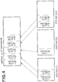
- Fig. 4 is a conceptual diagram of slot management according to the reference embodiment.
- Packages are physically installed into slots of each of the systems connected to the network and having the system ID. Information on the packages is unitarily integrated into a virtual slot database and the master system manages the virtual slot database.
- the master controls slots while referring to this virtual slot database.
- slots belong to the system other than the master, the slots are present physically at a remote location connected to the master by an IP network. However, the master can handle the slots as if they are its own slots without knowledge that the physical slots are at remote locations.
- the master can handle terminals and lines connected to the packages installed into the slots as if they are terminals and lines connected to the master.
- Fig. 5 shows the systems representing the above-stated manners.
- Packages connecting terminals, packages accommodating therein lines connected to a public line, and packages accommodating therein IP lines connected to the IP network are installed into a system having system ID: 1, a system having system ID: 2, and a system having system ID: 3, respectively.
- each of the systems can freely control the terminals, lines and the like accommodated in the packages connected to the slots as if they are its own terminals, lines and the like.
- the systems shown in Fig. 5 are built on a client-server architecture in which one master controls slaves.
- the master performs call processings on all the main devices including the master and manages a database.
- the master also manages virtual slots.
- IP internet protocol
- the systems 1, 2, and 3 include packages accommodating therein terminals, packages accommodating therein ordinary lines, and packages accommodating therein IP lines, respectively.
- the virtual slot database manages information on these packages. While the master basically manages the data, each of the slaves holds the same data in case of replacement of the master.
- Fig. 6 shows data flow for conventional package control.
- upstream data from a package is transmitted from a slot I/F module 101 to a CAPS (call control module)/OPMS (package and terminal management module) 105 via an IOCS (input/output control module) 103.
- CAPS call control module
- OPMS packet and terminal management module
- IOCS input/output control module
- the CAPS/OPMS 105 processes the upstream data and transmits a downstream command to the slot I/F module 101 via the IOCS 103. For example, if a package is installed into a slot, then data is transmitted to the CAPS/OMPS 105 as upstream data, and the CAPS/OMPS 105 recognizes package installation and exercises a starting control over the package, i.e., permits the package to be active. If a terminal connected to the package installed into the slot is off the hook, the slot I/F module 101 transmits data indicating that the terminal is off the hook to the CAPS/OPMS 105 as upstream data. In response to the upstream data, the CAPS/OPMS 105 transmits a command to produce a dial tone from the terminal to the slot I/F 101 via the IOCS 103 as downstream data.
- Fig. 7 shows data flow according to the reference embodiment.
- slot management by networking is realized by additionally providing slot control modules 107 each controlling slot input/output and a slot management module 109 managing slot information.
- Upstream data from one slot is subjected to a temporary spooling by one of the slot control modules 107 corresponding to a system including the slot and then transmitted to the slot management module 109 of the master controlling the system. If the system is the master, the upstream data is transmitted to its own slot management module 109.
- the management module 109 exercises such a control that it appears to the IOCS 103 that is a higher module that the data transmitted to the slot management module 109 is transmitted from a certain slot.
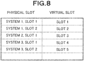
- the slot management module 109 receives data from a specific slot of a certain system and the specific slot is a slot of the system that has not been recognized so far, the slot management module 109 newly assigns a virtual slot number to the slot and subsequently regards the slot of the system as the slot to which the virtual slot number is assigned.
- a virtual slot number 1 is assigned to the slot 1.
- the higher module such as the IOCS 103 or the CAPS/OPMS 105 regards the data transmitted from the slot 1 of the system 1 as data from its own slot 1 even without knowledge of the network.
- downstream data is to be actually transmitted to a slot to issue a command to hardware, the command is issued to a slot of an appropriate system while referring to the physical slot/virtual slot contrast table 111.
- the command is transmitted to the slot control modules 107 of the systems and commands are transmitted to actual packages of the systems, respectively.
- processings are performed using virtual slot numbers.
- parts visible to a user such as setting of system data, it is often desired to perform a processing while identifying by which slot in which system the processing is performed.
- settings and the like can be made using physical slots while referring to the physical slot/virtual slot contrast table 111.
- the reference embodiment solves many of the conventional problems by attaining the central control networking system architecture so as to avoid problems with a distributed networking system architecture.
- the reference embodiment disadvantageously bears system vulnerability. Namely, according to the reference embodiment, from the nature of the reference embodiment, one main device acting as the master (hereinafter, “master main device”) exercises central control over all the resources on the network and manages all the main devices acting as slaves (hereinafter, “slave main devices”). Due to this, if the master main device malfunctions due to some failure, all the slave main devices connected to the master main device malfunction accordingly, with the result that the entire network malfunctions.
- master main device exercises central control over all the resources on the network and manages all the main devices acting as slaves (hereinafter, “slave main devices”). Due to this, if the master main device malfunctions due to some failure, all the slave main devices connected to the master main device malfunction accordingly, with the result that the entire network malfunctions.
- US 2004/0085965 A1 discloses a main device redundancy configuration of a networking system architecture comprising a plurality of main devices, one of the main devices acting as a master main device, remaining main devices other than the master main device acting as slave main devices, wherein if the master main device malfunctions, one of the slave main devices substitutes for the master main device to act as a new master main device.
- JP 2003-345407 A discloses a data equivalence method among duplexed PLCs wherein a data memory of a CPU of a PLC1 on a master side is composed by a dual port memory.
- a current data memory of a duplexed interface reads data from one of the ports of the dual port memory on a steady basis.
- a previous value data memory copies data of a current data memory at the time of completion of data reading.
- Equivalence processing parts transfer data of the previous value data memory to a data memory of a PLC2 on a slave side in the event of occurrence of abnormality in the PLC on the master side and obtain data equivalence.
- the present invention is an improvement of the reference embodiment. It is an object of the present invention to improve robustness of an entire networking system architecture in case of such failures as network malfunctioning by providing redundancy to the networking system architecture. This object is achieved with the features of the claims.
- a main device redundancy configuration as described includes a plurality of main devices, one of the main devices acting as a master main device, remaining main devices other than the master main device acting as slave main devices, wherein if the master main device malfunctions, one of the slave main devices substitutes for the master main device to act as a new master main device.
- priorities are set to the main devices, respectively, and the main device having the highest priority among the main devices acts as the new master main device if the current master main device malfunctions.
- the main device redundancy configuration if one of the main devices compares the priorities of all the other main devices with the priority of one of the main devices and the priority of one of the main devices is higher than the priorities of all the other main devices, then one of the main devices acts as the master main device and notifies the other main devices that one of the main devices is the master main device in response to inquiries from the other main devices, and if each of the other main devices receives a notification indicating that one of the main devices acts as the master main device, each of the other main devices recognizes that each of the other main devices is one of the slave main devices.
- the slave main devices other than the master main device hold system data held by the master main device.
- a communication between a terminal and the master main device is held via one of the slave main devices.
- a main device acting as a master main device malfunctions, then a main device to substitute for the master main device is selected from among slave main devices connected to the master main device, and the selected main device operates as a new master main device, thereby avoiding the conventional problems.
- slave main devices connected to the master main device sense that the master main device malfunctions, and a new main device to substitute for the master main device is selected from among all the slave main devices according to preset priorities.
- the slave main device that has been changed to the new or substitute master main device starts operating as the master main device and controls all the slave main devices.
- the new or substitute master main device is uniquely selected based on priorities set to the main devices, respectively, and the selected main device succeeds to functions of the master main device.
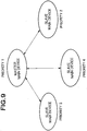
- Figs. 9 and 10 are conceptual diagrams of the networking system architecture according to the first embodiment of the present invention.
- each arrow indicates a communication relation and bidirectional communication is always held between the master main device and each of the slave main devices.
- the master main device If the master main device malfunctions or communication breaks down for such a reason as a network failure, then the master main device is replaced by another main device, and a state changes from a state shown in Fig. 9 to a state shown in Fig. 10 .
- each ellipse represents a main device and a master main device priority is set to each main device as system data.
- the main device having the highest master main device priority is selected from among all the operating main devices as the substitute master main device and starts operating as the main device.
- IP addresses are set to all the main devices, respectively.
- Each of the slave main devices always monitors connection to the master main device. If a communication with the master main device cannot be held for predetermined time or longer, then it is determined that the master main device malfunctions or a network failure occurs, and selection of the substitute master main device starts.
- the substitute master main device is selected by causing each main device to inquire all the other main devices about their priorities.
- the inquiry is made by sending a specific packet to the other main devices (expressed by IP addresses) on the IP in a list.
- Each of the main devices receiving this specific package transmits its priority to the sender main device.
- Fig. 11 is a conceptual diagram of the priority inquiry.
- each ellipse represents a main device which is being inquired about the priority, and each arrow represents that an inquiry is being made. As shown in Fig. 11 , the priority inquiry is made as a round robin.
- the main device If one of the main devices receives responses from all the other main devices in the list owned by the main device and the main device has the highest priority, the main device starts operating as the master main device. The main device from which no response is transmitted after passage of certain time is considered to malfunction, and the main device receiving the responses from the other main devices determines which has the highest priority.
- the main device If the main device inquiring the other main devices about their priorities is determined as the master main device, the main device notifies all the other main devices that the main device acts as the master main device from this time on.
- the main devices having lower priorities keep transmitting inquiries until the main device having the highest priority becomes the master main device.
- the main device acting as the master main device starts operating as the master main device while the main devices having the lower priority keep transmitting the inquiries. Due to this, each of the main devices having the lower priorities receives a response from the new master main device indicating that the main device acts as the master main device. After receiving the response, the other main devices are connected to the master main device that has transmitted the response and start operating as slave main devices.
- each of the main devices becomes the master main device or the slave main device.
- the master main device having the highest priority can be uniquely selected and a new network centering around the selected master main device can be created.
- the main devices are connected to one another by an IP network and have unique IP addresses and master main device priorities, respectively.
- Each of the main devices also includes a list of all the other main devices constituting the network.
- the main devices To identify each main device from the other main devices, the main devices have unique IDs, respectively.
- the IDs will be referred to as "system IDs" hereinafter.
- the system IDs can be considered to be identical to the respective master main device priorities.
- Fig. 12 is a configuration diagram of the networking system architecture according to the first embodiment.
- the main devices are uniquely given the IP addresses and the system IDs, respectively, and hold, as data, information on the IP addresses and the system IDs of the other main devices.
- the master main device If the master main device malfunctions or the master main device is not decided yet during construction of the network, the master main device is decided based on the information on the IP addresses and the system IDs.
- Each of the main devices holds setting information on a telephone, a line, and the like as a file called "system data”.
- the master main device manages information on all the slave main devices and operates. Due to this, the master main device refers to the system data held by the slave main devices.
- the main device acting as the new or substitute master main device refers to its own system data. Due to this, the main devices that may possibly act as the master main device need to hold the same system data as that of the system currently acting as the master main device.
- the central control networking system architecture introduces a mechanism in which latest system data is always synchronously transmitted to the slave master devices under control of the master main device whenever the master main device updates the system data.
- main device acts as the master main device depends on an order of rising at the time of initial construction of the network systems. This method is unfavorable if it is desired to allow a specific main device to act as the master main device.
- the forced setting of the master main device is made by designating the system ID of the main device that is to act as the master main device. For example, if a certain telephone terminal depresses a specific number (e.g., #999) and the system ID, the main device having the depressed system ID is forced to act as the master main device.
- a specific number e.g., #999
- This operation can be made by whichever system terminal connected to the network.
- the master main device can determine which system ID is the system ID of the new master main device. Therefore, the master main device acquires the IP address of the new master main device from the list of IP addresses held by the master main device, and transmits a command to the effect that a destination of the command is the master main device, to the new master main device as a packet.
- the main device having received this command starts operating as the master main device and notifies all the main devices that the master main device has been changed over.
- the resource central control networking system architecture includes the redundancy function, whereby the master main device controlling the entire network can be changed over and the system robustness is improved.
- the first embodiment has, however, the following problems.
- the mater main device is replaced by another master device and communication terminals such as an external CTI (Computer Telephony Integration) server and an ACD-MIS (Automatic Call Distributor-Management Information System) cannot communicate with the main master device that replaces the original communication partner. Due to this, these communication terminals cannot hold communication with the new master main device.
- the communication terminals such as the external CTI server and the ACD-MIS need to be informed which main device on the network acts as the master main device in advance.
- the second embodiment avoids the problems with the first embodiment by causing the main devices other than the master main device to transfer (redirect) communication from the communication terminals such as the CTI server and the ACT-MIS to the master main device.
- the main device that recognizes connection from a communication terminal is not the master main device, that is, is the slave main device, then the main device redirects the connection from the communication terminal to the master main device to which the main device is connected. Further, the main device transfers data from the communication terminal to the master main device and relays data from the master main device to the communication terminal.
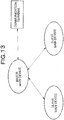
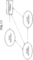
- Fig. 13 is a conceptual diagram of connection of the master main device to the communication terminal in the resource central control networking system architecture according to the second embodiment.
- the main devices acting as slave main devices communicate with the master main device and entirely obey commands from the master main device.
- the communication terminal communicates with the master main device according to the preset IP address, acquires call information, controls the main devices, and does the other things.
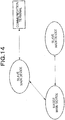
- Fig. 14 is a conceptual diagram showing this state.
- the main device that has acted as the slave main device is changed to the master main device and the main device that has acted as the master main device is changed to a slave main device.
- the communication terminal since the communication terminal is only configured to communicate with a single main device, the communication terminal has no choice but to communicate with the communication partner that has acted as the master main device before.
- the communication partner is not already the master main device but the slave main device obeying commands from the master main device. Due to this, the communication partner can communicate with the communication terminal but cannot transmit appropriate information to the communication terminal.
- the second embodiment therefore, provides a technique for relaying the connection to the communication terminal so that it appears to the communication terminal that the communication terminal directly communicates with the new master main device and to the new master main device that the new master main device directly communicates with the communication terminal.
- the main devices are connected to one another by the internet protocol and the master main device and each of the slave main devices communicate with each other. While the master main device manages all of the call information, the resource information, and the system information, each of the slave main devices basically includes only the communication function and cannot directly perform appropriate processings on the communication terminal.
- the communication terminal can be connected only to a specific main device.
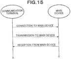
- Fig. 15 is a conceptual diagram showing conventional communication between a communication terminal and a main device.
- the main device opens a specific port set based on system data for connection to or from the communication terminal, and awaits the connection at the specific port.
- the communication terminal establishes connection to an IP address and the port of the main device.
- connection is held by an application of the communication terminal and the IP address and port of the main device need to be set in advance.
- the main device prepares a CTI communication port 8000 (not shown) and awaits connection.
- the communication terminal starts a CTI application, sets the IP address and the communication port 8000 of the main device, and connects to the main device.
- the communication terminal transmits a command to the main device by transmitting data to the main device, and obtains a result by receiving data from the main device.
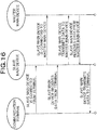
- Fig. 16 is a conceptual diagram showing communication according to the second embodiment.
- the main device If one main device receives connection from the communication terminal and the main device is not the master main device but the slave main device, the main device is connected to the master main device while keeping the connection from the communication terminal.
- the slave main device can await the connection from the communication terminal at the same port as that of the master main device and can connect the communication terminal to a waiting port of the master main device.
- the master main device that has received the connection from the slave main device recognizes that the connection is the connection from the communication terminal and starts services.
- the communication terminal recognizes that the communication terminal has been connected to the master main device by the connection to the slave main device and starts operating.
- the slave main device transfers data from the communication terminal to the master main device and transfers data from the master main device to the communication terminal.
- the communication. terminal can communicate with the master main device without knowledge of the location o the master main device at all.
- the application of the communication terminal is manufactured by the third party, the application can be used without any problems. Moreover, since the master main device can recognize that the communication terminal is connected to the master main device as before, there is no need to change processings.
- the communication terminal can communicate with the master main device whichever the communication terminal is connected to. It, therefore, suffices to register one of the main devices on the network to the communication terminal as a connection destination and there is no need to have knowledge of which acts as the master main device.
- the problem that the communication terminal cannot be connected to the new master main device due to the changeover of the master main device can be avoided using the redundancy function. Besides, it is possible to guarantee the same operations for the communication terminal and the master main device as before, so that there is no need to change applications.
Landscapes
- Engineering & Computer Science (AREA)
- Computer Networks & Wireless Communication (AREA)
- Signal Processing (AREA)
- Telephonic Communication Services (AREA)
- Data Exchanges In Wide-Area Networks (AREA)
Claims (10)
- Netzwerksystem mit einer Hauptgerät-Redundanzkonfiguration mit mehreren Hauptgeräten, die miteinander kommunizieren,wobei eines der Hauptgeräte als ein Master-Hauptgerät dient,die vom Master-Hauptgerät verschiedenen übrigen Hauptgeräte als Slave-Hauptgeräte dienen,das Hauptgerät, das als ein Master-Hauptgerät dient, dazu eingerichtet ist, über eine Kommunikation zwischen dem Master-Hauptgerät und Slave-Hauptgeräten auf Pakete in Hauptgeräten zuzugreifen, die dazu eingerichtet sind, als Slave-Hauptgeräte zu dienen,wobei, wenn das Master-Hauptgerät fehlerhaft arbeitet, eines der Slave-Hauptgeräte dazu eingerichtet ist, das Master-Hauptgerät zu ersetzen und als ein neues Master-Hauptgerät zu dienen;dadurch gekennzeichnet, dassjedes Hauptgerät seine eigene physikalische IP-Adresse hat und die physikalische IP-Adresse jedes Hauptgeräts dazu eingerichtet ist, für eine Kommunikation zwischen Hauptgeräten verwendet zu werden; unddass, wenn auf einem Telefonendgerät eine bestimmte Zahl und eine System-ID des Hauptgeräts gedrückt wird, das als das Master-Hauptgerät dienen soll, das Master-Hauptgerät ein neues Master-Hauptgerät mit der System-ID bestimmt, die durch das Telefonendgerät gedrückt wird, die physikalische IP-Adresse des neuen Master-Hauptgeräts aus einer Liste physikalischer IP-Adressen abruft, die im Master-Hauptgerät gespeichert ist, und einen Befehl, der anzeigt, dass ein Hauptgerät, das diesen Befehl empfängt, als ein Master-Hauptgerät arbeitet, als ein Paket an das neue Master-Hauptgerät überträgt, und wobei das Hauptgerät, das den Befehl empfangen hat, als das Master-Hauptgerät arbeitet und alle Hauptgeräte darüber benachrichtigt, dass das Master-Hauptgerät gewechselt hat.
- Netzwerksystem nach Anspruch 1,
wobei jeweils Prioritäten für die Hauptgeräte gesetzt werden und das Hauptgerät mit der höchsten Priorität unter den anderen Hauptgeräten als das neue Hauptgerät dient, wenn das aktuelle Master-Hauptgerät fehlerhaft arbeitet. - Netzwerksystem nach Anspruch 2,wobei, wenn eines der Hauptgeräte die Prioritäten aller anderen Hauptgeräte mit der Priorität eines der Hauptgeräte vergleicht und die Priorität eines der Hauptgeräte höher ist als die Prioritäten aller anderen Hauptgeräte, eines der Hauptgeräte als das Master-Hauptgerät dient und die anderen Hauptgeräte in Antwort auf Anfragen von den anderen Hauptgeräten darüber benachrichtigt, dass eines der Hauptgeräte das Master-Hauptgerät ist, undwenn jedes der anderen Hauptgeräte eine Benachrichtigung empfängt, die anzeigt, dass eines der Hauptgeräte als das Master-Hauptgerät dient, jedes der anderen Hauptgeräte erkennt, dass jedes der anderen Hauptgeräte eines der Slave-Hauptgeräte ist.
- Netzwerksystem nach Anspruch 1, 2 oder 3,
wobei die Slave-Hauptgeräte, die vom Master-Hauptgerät verschieden sind, Systemdaten speichern, die im Master-Hauptgerät gespeichert sind. - Netzwerksystem nach Anspruch 1, 2, 3 oder 4,
wobei eine Kommunikation zwischen einem Endgerät und dem Master-Hauptgerät über eines der Slave-Hauptgeräte ausgeführt wird. - Verfahren zum Ersetzen eines Hauptgeräts für eine Netzwerksystemarchitektur, die mehrere miteinander kommunizierende Hauptgeräte aufweist,wobei eines der Hauptgeräte als ein Master-Hauptgerät dient,die vom Master-Hauptgerät verschiedenen übrigen Hauptgeräte als Slave-Hauptgeräte dienen,das Hauptgerät, das als Master-Hauptgerät dient, über eine Kommunikation zwischen dem Master-Hauptgerät und Slave-Hauptgeräten auf Pakete in Hauptgeräten zugreift, die als die Slave-Hauptgeräte dienen,wobei, wenn das Master-Hauptgerät fehlerhaft arbeitet, eines der Slave-Hauptgeräte das Master-Hauptgerät ersetzt und als neues Master-Hauptgerät dient;dadurch gekennzeichnet, dassjedes Hauptgerät seine eigene physikalische IP-Adresse hat und die physikalische IP-Adresse jedes Hauptgeräts dazu eingerichtet ist, für eine Kommunikation zwischen Hauptgeräten verwendet zu werden; unddass, wenn auf einem Telefonendgerät eine bestimmte Zahl und eine System-ID des Hauptgeräts gedrückt wird, das als das Master-Hauptgerät dienen soll, das Master-Hauptgerät ein neues Master-Hauptgerät mit der System-ID bestimmt, die auf dem Telefonendgerät gedrückt wird, die physikalische IP-Adresse des neuen Master-Hauptgeräts aus einer Liste physikalischer IP-Adressen abruft, die im Master-Hauptgerät gespeichert ist, und einen Befehl, der anzeigt, dass ein Hauptgerät, das diesen Befehl empfängt, als ein Master-Hauptgerät arbeitet, als ein Paket an das neue Master-Hauptgerät überträgt, und das Hauptgerät, das den Befehl empfangen hat, einen Betrieb als Master-Hauptgerät startet und alle Hauptgeräte darüber benachrichtigt, dass das Master-Hauptgerät gewechselt hat.
- Verfahren zum Ersetzen eines Hauptgeräts für eine Netzwerksystemarchitektur nach Anspruch 6,
wobei jeweils Prioritäten für die Hauptgeräte gesetzt werden und das Hauptgerät mit der höchsten Priorität unter den anderen Hauptgeräten als das neue Hauptgerät dient, wenn das aktuelle Master-Hauptgerät fehlerhaft arbeitet. - Verfahren zum Ersetzen eines Hauptgeräts für eine Netzwerksystemarchitektur nach Anspruch 7,wobei, wenn eines der Hauptgeräte die Prioritäten aller anderen Hauptgeräte mit der Priorität eines der Hauptgeräte vergleicht und die Priorität eines der Hauptgeräte höher ist als die Prioritäten aller anderen Hauptgeräte, eines der Hauptgeräte als das Master-Hauptgerät dient und die anderen Hauptgeräte in Antwort auf Anfragen von den anderen Hauptgeräten darüber benachrichtigt, dass eines der Hauptgeräte das Master-Hauptgerät ist, undwenn jedes der anderen Hauptgeräte eine Benachrichtigung empfängt, die anzeigt, dass eines der Hauptgeräte als das Master-Hauptgerät dient, jedes der anderen Hauptgeräte erkennt, dass jedes der anderen Hauptgeräte eines der Slave-Hauptgeräte ist.
- Verfahren zum Ersetzen eines Hauptgeräts für eine Netzwerksystemarchitektur nach Anspruch 6, 7 oder 8,
wobei die Slave-Hauptgeräte, die vom Master-Hauptgerät verschieden sind, Systemdaten speichern, die im Master-Hauptgerät gespeichert sind. - Verfahren zum Ersetzen eines Hauptgeräts für eine Netzwerksystemarchitektur nach Anspruch 6, 7, 8 oder 9,
wobei eine Kommunikation zwischen einem Endgerät und dem Master-Hauptgerät über eines der Slave-Hauptgeräte ausgeführt wird.
Applications Claiming Priority (1)
| Application Number | Priority Date | Filing Date | Title |
|---|---|---|---|
| JP2007132955 | 2007-05-18 |
Publications (2)
| Publication Number | Publication Date |
|---|---|
| EP1993232A1 EP1993232A1 (de) | 2008-11-19 |
| EP1993232B1 true EP1993232B1 (de) | 2019-04-10 |
Family
ID=39673243
Family Applications (1)
| Application Number | Title | Priority Date | Filing Date |
|---|---|---|---|
| EP08155584.9A Active EP1993232B1 (de) | 2007-05-18 | 2008-05-02 | Redundanzeinstellung und Austauschverfahren für ein Hauptgerät |
Country Status (4)
| Country | Link |
|---|---|
| US (1) | US8473774B2 (de) |
| EP (1) | EP1993232B1 (de) |
| AU (1) | AU2008201944B2 (de) |
| CA (1) | CA2630014C (de) |
Families Citing this family (9)
| Publication number | Priority date | Publication date | Assignee | Title |
|---|---|---|---|---|
| US8244949B2 (en) * | 2007-05-18 | 2012-08-14 | Nec Infrontia Corporation | Slot interface access unit, method thereof, and program thereof, as well as redundancy configuration of main unit, and replacing method of the same |
| TW201117590A (en) * | 2009-11-10 | 2011-05-16 | Aten Int Co Ltd | Method and system of desktop broadcasting |
| JP5057121B2 (ja) * | 2010-02-01 | 2012-10-24 | Necインフロンティア株式会社 | Sip端末制御システム及びsip端末制御方法 |
| US20120173713A1 (en) * | 2010-12-30 | 2012-07-05 | Brocade Communication Systems, Inc. | Resources monitoring and recovery |
| CN106856489B (zh) | 2015-12-08 | 2020-09-08 | 阿里巴巴集团控股有限公司 | 一种分布式存储系统的服务节点切换方法和装置 |
| CN109104348B (zh) * | 2017-06-21 | 2020-09-15 | 比亚迪股份有限公司 | 基于CANopen协议的列车网络数据传输方法、系统及其装置 |
| US20190163530A1 (en) * | 2017-11-24 | 2019-05-30 | Industrial Technology Research Institute | Computation apparatus, resource allocation method thereof, and communication system |
| CN108599981A (zh) * | 2018-03-13 | 2018-09-28 | 迈普通信技术股份有限公司 | 业务卡的管理方法、业务卡及通信设备 |
| CN113489601B (zh) * | 2021-06-11 | 2024-05-14 | 海南视联通信技术有限公司 | 基于视联网自治云网络架构的抗毁方法和装置 |
Family Cites Families (42)
| Publication number | Priority date | Publication date | Assignee | Title |
|---|---|---|---|---|
| US5255388A (en) * | 1990-09-26 | 1993-10-19 | Honeywell Inc. | Synchronizing slave processors through eavesdrop by one on a write request message directed to another followed by comparison of individual status request replies |
| JP3181301B2 (ja) | 1991-03-11 | 2001-07-03 | 株式会社東芝 | バス拡張システム |
| JPH04339492A (ja) | 1991-05-16 | 1992-11-26 | Matsushita Electric Ind Co Ltd | 構内自動交換機 |
| JPH05108687A (ja) | 1991-05-29 | 1993-04-30 | Laurel Bank Mach Co Ltd | 自動機システムにおける運用制御方式 |
| JPH07168790A (ja) | 1993-12-15 | 1995-07-04 | Oki Electric Ind Co Ltd | 情報処理装置 |
| US5774668A (en) * | 1995-06-07 | 1998-06-30 | Microsoft Corporation | System for on-line service in which gateway computer uses service map which includes loading condition of servers broadcasted by application servers for load balancing |
| US5884032A (en) | 1995-09-25 | 1999-03-16 | The New Brunswick Telephone Company, Limited | System for coordinating communications via customer contact channel changing system using call centre for setting up the call between customer and an available help agent |
| WO1997035255A1 (fr) | 1996-03-15 | 1997-09-25 | Hitachi, Ltd. | Systeme d'ordinateur virtuel reparti |
| US6092214A (en) * | 1997-11-06 | 2000-07-18 | Cisco Technology, Inc. | Redundant network management system for a stackable fast ethernet repeater |
| US6418493B1 (en) | 1997-12-29 | 2002-07-09 | Intel Corporation | Method and apparatus for robust addressing on a dynamically configurable bus |
| JP3449919B2 (ja) | 1998-05-11 | 2003-09-22 | 株式会社大興電機製作所 | ボタン電話システム |
| JPH11353284A (ja) | 1998-06-10 | 1999-12-24 | Hitachi Ltd | ジョブ再実行方法 |
| JP3887130B2 (ja) | 1999-07-30 | 2007-02-28 | 株式会社東芝 | 高可用性計算機システム及び同システムにおけるデータバックアップ方法 |
| US7464133B1 (en) | 1999-10-05 | 2008-12-09 | Fujitsu Limited | Server/client system |
| US6643795B1 (en) * | 2000-03-30 | 2003-11-04 | Hewlett-Packard Development Company, L.P. | Controller-based bi-directional remote copy system with storage site failover capability |
| US7120683B2 (en) * | 2000-04-03 | 2006-10-10 | Zarlink Semiconductor V.N. Inc. | Single switch image for a stack of switches |
| US6983362B1 (en) * | 2000-05-20 | 2006-01-03 | Ciena Corporation | Configurable fault recovery policy for a computer system |
| JP2001358736A (ja) | 2000-06-15 | 2001-12-26 | Mitsubishi Electric Corp | リング型ネットワークシステム |
| US8204082B2 (en) * | 2000-06-23 | 2012-06-19 | Cloudshield Technologies, Inc. | Transparent provisioning of services over a network |
| US6990606B2 (en) * | 2000-07-28 | 2006-01-24 | International Business Machines Corporation | Cascading failover of a data management application for shared disk file systems in loosely coupled node clusters |
| US6954436B1 (en) * | 2001-02-28 | 2005-10-11 | Extreme Networks, Inc. | Method and apparatus for selecting redundant routers using tracking |
| US7042842B2 (en) | 2001-06-13 | 2006-05-09 | Computer Network Technology Corporation | Fiber channel switch |
| KR100440969B1 (ko) * | 2002-05-23 | 2004-07-21 | 삼성전자주식회사 | 네트워킹 방법 및 그 장치 |
| JP2003345407A (ja) | 2002-05-30 | 2003-12-05 | Meidensha Corp | 二重化plc間のデータ等価方式 |
| US7243253B1 (en) * | 2002-06-21 | 2007-07-10 | Redback Networks Inc. | Repeating switching of a cross-connect and a timing source in a network element through the use of a phase adjuster |
| US7197660B1 (en) * | 2002-06-26 | 2007-03-27 | Juniper Networks, Inc. | High availability network security systems |
| US7362700B2 (en) * | 2002-06-27 | 2008-04-22 | Extreme Networks, Inc. | Methods and systems for hitless restart of layer 3 packet forwarding |
| US7636364B2 (en) | 2002-10-31 | 2009-12-22 | Force 10 Networks, Inc. | Redundant router network |
| US7152182B2 (en) * | 2003-06-06 | 2006-12-19 | Hewlett-Packard Development Company, L.P. | Data redundancy system and method |
| US7178055B2 (en) * | 2003-06-06 | 2007-02-13 | Hewlett-Packard Development Company, L.P. | Method and system for ensuring data consistency after a failover event in a redundant data storage system |
| JP2005018510A (ja) * | 2003-06-27 | 2005-01-20 | Hitachi Ltd | データセンタシステム及びその制御方法 |
| US7668923B2 (en) * | 2003-10-14 | 2010-02-23 | International Business Machines Corporation | Master-slave adapter |
| US7188273B2 (en) * | 2003-11-24 | 2007-03-06 | Tsx Inc. | System and method for failover |
| US7483370B1 (en) * | 2003-12-22 | 2009-01-27 | Extreme Networks, Inc. | Methods and systems for hitless switch management module failover and upgrade |
| US8203933B2 (en) * | 2003-12-23 | 2012-06-19 | At&T Intellectual Property I, L.P. | Method and system for automatically identifying a logical circuit failure in a data network |
| JP4320602B2 (ja) | 2004-02-26 | 2009-08-26 | 日本電気株式会社 | 加入者ユニット冗長システムおよび加入者ユニット冗長方法 |
| US9264384B1 (en) * | 2004-07-22 | 2016-02-16 | Oracle International Corporation | Resource virtualization mechanism including virtual host bus adapters |
| JP4710518B2 (ja) * | 2005-09-28 | 2011-06-29 | 株式会社日立製作所 | 計算機システムとそのブート制御方法 |
| US8448162B2 (en) * | 2005-12-28 | 2013-05-21 | Foundry Networks, Llc | Hitless software upgrades |
| US8295162B2 (en) * | 2006-05-16 | 2012-10-23 | At&T Intellectual Property I, L.P. | System and method to achieve sub-second routing performance |
| US7725764B2 (en) * | 2006-08-04 | 2010-05-25 | Tsx Inc. | Failover system and method |
| US8873377B2 (en) * | 2009-11-18 | 2014-10-28 | Juniper Networks, Inc. | Method and apparatus for hitless failover in networking systems using single database |
-
2008
- 2008-04-25 CA CA2630014A patent/CA2630014C/en active Active
- 2008-04-28 US US12/110,389 patent/US8473774B2/en active Active
- 2008-05-01 AU AU2008201944A patent/AU2008201944B2/en active Active
- 2008-05-02 EP EP08155584.9A patent/EP1993232B1/de active Active
Non-Patent Citations (1)
| Title |
|---|
| None * |
Also Published As
| Publication number | Publication date |
|---|---|
| US20080288686A1 (en) | 2008-11-20 |
| AU2008201944B2 (en) | 2013-07-04 |
| EP1993232A1 (de) | 2008-11-19 |
| US8473774B2 (en) | 2013-06-25 |
| CA2630014C (en) | 2014-05-27 |
| CA2630014A1 (en) | 2008-11-18 |
| AU2008201944A1 (en) | 2008-12-04 |
Similar Documents
| Publication | Publication Date | Title |
|---|---|---|
| EP1993232B1 (de) | Redundanzeinstellung und Austauschverfahren für ein Hauptgerät | |
| EP2003814B1 (de) | Zugangsvorrichtung, Zugangsverfahren und Programm für Schlitzschnittstelle | |
| JP5366177B2 (ja) | スロットインターフェースアクセス装置、その方法及びそのプログラム並びに主装置の冗長構成及び代替方法 | |
| US8285905B2 (en) | Redundancy configuration and replacement method in a system including a master main unit and slave main units | |
| CN112381346A (zh) | 一种基于api网关的产品工艺配方参数下发校验方法及系统 | |
| EP2001163B1 (de) | Zugangsvorrichtung und zugangsverfahren für schlitzschnittstelle | |
| CA2643001C (en) | Slot interface access unit, method thereof, and program thereof, as well as redundancy configuration of main unit, and replacing method of the same | |
| JP2002354049A (ja) | 回線管理システム | |
| JP6282222B2 (ja) | 通信装置 | |
| JP5088730B2 (ja) | リソース集中管理方式のネットワーキングにおける音声パス制御とリソースの管理方法及びそのシステム | |
| WO2025180186A1 (zh) | 通信系统、更新操作系统的方法和线卡 | |
| JP2001136224A (ja) | 通信回線制御方法及び通信回線制御システム | |
| CN117692464A (zh) | 多运算节点的服务器与通讯处理方法 | |
| JP2009118357A (ja) | イーサネットスイッチ |
Legal Events
| Date | Code | Title | Description |
|---|---|---|---|
| PUAI | Public reference made under article 153(3) epc to a published international application that has entered the european phase |
Free format text: ORIGINAL CODE: 0009012 |
|
| AK | Designated contracting states |
Kind code of ref document: A1 Designated state(s): AT BE BG CH CY CZ DE DK EE ES FI FR GB GR HR HU IE IS IT LI LT LU LV MC MT NL NO PL PT RO SE SI SK TR |
|
| AX | Request for extension of the european patent |
Extension state: AL BA MK RS |
|
| 17P | Request for examination filed |
Effective date: 20090513 |
|
| AKX | Designation fees paid |
Designated state(s): DE GB |
|
| RAP1 | Party data changed (applicant data changed or rights of an application transferred) |
Owner name: NEC PLATFORMS, LTD. |
|
| 17Q | First examination report despatched |
Effective date: 20161125 |
|
| GRAP | Despatch of communication of intention to grant a patent |
Free format text: ORIGINAL CODE: EPIDOSNIGR1 |
|
| INTG | Intention to grant announced |
Effective date: 20181023 |
|
| GRAS | Grant fee paid |
Free format text: ORIGINAL CODE: EPIDOSNIGR3 |
|
| GRAA | (expected) grant |
Free format text: ORIGINAL CODE: 0009210 |
|
| AK | Designated contracting states |
Kind code of ref document: B1 Designated state(s): DE GB |
|
| REG | Reference to a national code |
Ref country code: GB Ref legal event code: FG4D |
|
| REG | Reference to a national code |
Ref country code: DE Ref legal event code: R096 Ref document number: 602008059649 Country of ref document: DE |
|
| REG | Reference to a national code |
Ref country code: DE Ref legal event code: R097 Ref document number: 602008059649 Country of ref document: DE |
|
| PLBE | No opposition filed within time limit |
Free format text: ORIGINAL CODE: 0009261 |
|
| STAA | Information on the status of an ep patent application or granted ep patent |
Free format text: STATUS: NO OPPOSITION FILED WITHIN TIME LIMIT |
|
| 26N | No opposition filed |
Effective date: 20200113 |
|
| REG | Reference to a national code |
Ref country code: DE Ref legal event code: R079 Ref document number: 602008059649 Country of ref document: DE Free format text: PREVIOUS MAIN CLASS: H04L0012240000 Ipc: H04L0041000000 |
|
| PGFP | Annual fee paid to national office [announced via postgrant information from national office to epo] |
Ref country code: DE Payment date: 20250521 Year of fee payment: 18 |
|
| PGFP | Annual fee paid to national office [announced via postgrant information from national office to epo] |
Ref country code: GB Payment date: 20250530 Year of fee payment: 18 |