EP1992828B1 - Device for configuring an aperture in a component - Google Patents
Device for configuring an aperture in a component Download PDFInfo
- Publication number
- EP1992828B1 EP1992828B1 EP08103816A EP08103816A EP1992828B1 EP 1992828 B1 EP1992828 B1 EP 1992828B1 EP 08103816 A EP08103816 A EP 08103816A EP 08103816 A EP08103816 A EP 08103816A EP 1992828 B1 EP1992828 B1 EP 1992828B1
- Authority
- EP
- European Patent Office
- Prior art keywords
- opening
- locking element
- component
- expanding
- band
- Prior art date
- Legal status (The legal status is an assumption and is not a legal conclusion. Google has not performed a legal analysis and makes no representation as to the accuracy of the status listed.)
- Expired - Fee Related
Links
- 238000009415 formwork Methods 0.000 description 12
- 238000009416 shuttering Methods 0.000 description 11
- 230000000903 blocking effect Effects 0.000 description 7
- 239000000853 adhesive Substances 0.000 description 1
- 230000001070 adhesive effect Effects 0.000 description 1
- 239000004566 building material Substances 0.000 description 1
- 238000010276 construction Methods 0.000 description 1
- 238000005516 engineering process Methods 0.000 description 1
- 230000002349 favourable effect Effects 0.000 description 1
- 229910052500 inorganic mineral Inorganic materials 0.000 description 1
- 238000009434 installation Methods 0.000 description 1
- 238000004519 manufacturing process Methods 0.000 description 1
- 239000011707 mineral Substances 0.000 description 1
Images

Classifications
-
- F—MECHANICAL ENGINEERING; LIGHTING; HEATING; WEAPONS; BLASTING
- F16—ENGINEERING ELEMENTS AND UNITS; GENERAL MEASURES FOR PRODUCING AND MAINTAINING EFFECTIVE FUNCTIONING OF MACHINES OR INSTALLATIONS; THERMAL INSULATION IN GENERAL
- F16B—DEVICES FOR FASTENING OR SECURING CONSTRUCTIONAL ELEMENTS OR MACHINE PARTS TOGETHER, e.g. NAILS, BOLTS, CIRCLIPS, CLAMPS, CLIPS OR WEDGES; JOINTS OR JOINTING
- F16B13/00—Dowels or other devices fastened in walls or the like by inserting them in holes made therein for that purpose
- F16B13/04—Dowels or other devices fastened in walls or the like by inserting them in holes made therein for that purpose with parts gripping in the hole or behind the reverse side of the wall after inserting from the front
- F16B13/06—Dowels or other devices fastened in walls or the like by inserting them in holes made therein for that purpose with parts gripping in the hole or behind the reverse side of the wall after inserting from the front combined with expanding sleeve
- F16B13/061—Dowels or other devices fastened in walls or the like by inserting them in holes made therein for that purpose with parts gripping in the hole or behind the reverse side of the wall after inserting from the front combined with expanding sleeve of the buckling type
-
- F—MECHANICAL ENGINEERING; LIGHTING; HEATING; WEAPONS; BLASTING
- F16—ENGINEERING ELEMENTS AND UNITS; GENERAL MEASURES FOR PRODUCING AND MAINTAINING EFFECTIVE FUNCTIONING OF MACHINES OR INSTALLATIONS; THERMAL INSULATION IN GENERAL
- F16B—DEVICES FOR FASTENING OR SECURING CONSTRUCTIONAL ELEMENTS OR MACHINE PARTS TOGETHER, e.g. NAILS, BOLTS, CIRCLIPS, CLAMPS, CLIPS OR WEDGES; JOINTS OR JOINTING
- F16B5/00—Joining sheets or plates, e.g. panels, to one another or to strips or bars parallel to them
- F16B5/06—Joining sheets or plates, e.g. panels, to one another or to strips or bars parallel to them by means of clamps or clips
- F16B5/0607—Joining sheets or plates, e.g. panels, to one another or to strips or bars parallel to them by means of clamps or clips joining sheets or plates to each other
- F16B5/0621—Joining sheets or plates, e.g. panels, to one another or to strips or bars parallel to them by means of clamps or clips joining sheets or plates to each other in parallel relationship
- F16B5/0642—Joining sheets or plates, e.g. panels, to one another or to strips or bars parallel to them by means of clamps or clips joining sheets or plates to each other in parallel relationship the plates being arranged one on top of the other and in full close contact with each other
Definitions
- the invention relates to a device for shuttering an opening in a component, the type mentioned in the preamble of claim 1 ( FR 2 398 208 A ).
- Such devices are used for covering or closing, in components such as walls or ceilings, arranged openings on a first side before these openings are filled from a second side with mineral building materials or other masses.
- a plurality of bores for receiving the dowel must first be introduced into the component laterally of the opening and corresponding holes are provided in the shuttering panel.
- the present invention has for its object to provide a device for boarding an opening in a component which avoids the disadvantages mentioned and which allows a simple and quick installation on a component and increased holding forces provides.
- At least one expansion band and a locking opening provided with a through-opening blocking element for a counter-locking element are arranged on the formwork element as a fastening means, wherein a distance between the locking element and the formwork element along the Gegensperrelements for spreading the Sp Sonbandes is reduced.
- the at least one expansion band is thereby spread out or deflected outwards at a reduction of the distance between the blocking element and the formwork element to the inner wall of the opening, so that the device is fixed frictionally or non-positively at the opening.
- the fixing of the device can advantageously take place from the side facing away from the shuttering element of the opening.
- the at least one spreading band has clawing elements on at least one flat side. These Verkrallungsetti increase in the determination of the device at the opening, the holding forces of the spreader on the inner wall of the opening.
- the Verkrallungsetti are formed as teeth of a toothing, the bumps of the inner wall can also engage behind a positive fit.
- the at least one expansion band is formed integrally with the blocking element.
- the blocking element is arranged on a first end of the spreading band facing away from the formwork element.
- a plurality of expansion bands are provided, which are connected to one another at their first ends facing away from the formwork element via the blocking element, whereby a symmetrical application of the holding forces relative to the inner wall is possible, in which the blocking element can be arranged axially in the opening.
- the shuttering element has a first part and a second part, which are hingedly connected to each other along a folding bearing. This makes it possible to reduce the formwork element by folding and pass through the opening in a component.
- the assembly of the device can be done entirely from the side of the opening, which is the side of the opening to strigalenden.
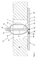
- FIGS. 1 to 3 a device 10 according to the invention for covering an opening 31 in a component 30 is shown, which has a plate-shaped shuttering element 11 and two expansion straps 13, 14 fixed thereto.
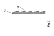
- the expansion bands 13, 14 each have at least on a flat side with a Verkrallungsianan 19, such.
- a locking element 15 is fixed to this, which connects both expansion bands 13, 14 with each other and which has a passage opening 16 arranged therein locking means (in the FIGS. 1 and 3 not visible) for a counter-locking element 17.
- the counter-locking element 17 may, for. B.
- the counter-locking element 17 and the expansion straps 13, 14 are presently connected to each other at their opposite the locking element 15 second ends 12 and preferably in one piece z. B. made as a plastic part.
- the expansion straps 13, 14 and the counter-locking element 17 are fixed to the shuttering element 11 at these second ends 12. This determination of the expansion bands 13, 14 and the counter locking element 17 on the formwork element 11 may, for. B. via a fastener 40 or z. B. also by an adhesive connection.
- the formwork element 11 is formed in two parts and has a first part 21 and a second part 22 which are connected to each other via a folding bearing 20.
- the first part 21 is pivotable in the direction of the arrow 23 relative to the second part 22, whereby the formwork element 11 is reduced in size so that it can pass through an opening 31 in a component 30 can.
Description
Die Erfindung betrifft eine Vorrichtung zum Verschalen einer Öffnung in einem Bauteil, der im Oberbegriff von Patentanspruch 1 genannten Art (
Es wird dabei z. B. eine Schalungsplatte, wie z. B. ein Schalungsbrett, mit mehreren Dübeln und in diesen eingedrehten Schrauben an einer ersten Seite der Öffnung angebracht um die Öffnung dort zu verschliessen. Dazu müssen zunächst seitlich der Öffnung mehrere Bohrungen zur Aufnahme der Dübel in das Bauteil eingebracht werden und entsprechende Löcher in der Schalungsplatte vorgesehen werden. Daraufhin kann die Schalungsplatte z. B. mit Schrauben in den Dübellöchern verankert werden. Diese Art der Befestigung ist recht aufwändig.It is z. B. a formwork panel, such as. B. a shuttering board, with several dowels and screwed in these screws attached to a first side of the opening to close the opening there. For this purpose, a plurality of bores for receiving the dowel must first be introduced into the component laterally of the opening and corresponding holes are provided in the shuttering panel. Then the formwork panel z. B. anchored with screws in the dowel holes. This type of attachment is quite expensive.
Aus der
Wird eine derartige Platte als Schalungselement zum Verschalen einer Öffnung in einem Bauteil verwendet, dann muss also seitlich der Öffnung wenigstens eine Bohrung für den Dübel erstellt werden, was zeitaufwändig ist.If such a plate is used as shuttering element for shuttering an opening in a component, then at least one bore for the plug must be created laterally of the opening, which is time-consuming.
Der vorliegenden Erfindung liegt die Aufgabe zugrunde, eine Vorrichtung zum Verschalen einer Öffnung in einem Bauteil bereitzustellen, die die genannten Nachteile vermeidet und die eine einfache und schnelle Montage an einem Bauteil ermöglicht und erhöhte Halte Kräfte bereitstellt.The present invention has for its object to provide a device for boarding an opening in a component which avoids the disadvantages mentioned and which allows a simple and quick installation on a component and increased holding forces provides.
Diese Aufgabe wird erfindungsgemäss durch die im kennzeichnenden Teil von Anspruch 1 genannten Massnahmen erreicht. Demnach sind an dem Schalungselement als Befestigungsmittel wenigstens ein Spreizband und ein mit einer Durchführöffnung versehenes Sperrelement für ein Gegensperrelement angeordnet, wobei ein Abstand zwischen dem Sperrelement und dem Schalungselement entlang des Gegensperrelements zum Spreizen des Spreizbandes verkleinerbar ist. Das wenigstens eine Spreizband wird dadurch bei einer Verkleinerung des Abstandes zwischen dem Sperrelement und dem Schalungselement nach aussen zur Innenwand der Öffnung hin gespreizt bzw. ausgelenkt, so dass die Vorrichtung an der Öffnung reib- bzw. kraftschlüssig fixiert wird. Das Fixieren der Vorrichtung kann dabei vorteilhaft von der dem Schalungselement abgewandten Seite der Öffnung aus erfolgen.This object is achieved according to the invention by the measures mentioned in the characterizing part of claim 1. Accordingly, at least one expansion band and a locking opening provided with a through-opening blocking element for a counter-locking element are arranged on the formwork element as a fastening means, wherein a distance between the locking element and the formwork element along the Gegensperrelements for spreading the Spreizbandes is reduced. The at least one expansion band is thereby spread out or deflected outwards at a reduction of the distance between the blocking element and the formwork element to the inner wall of the opening, so that the device is fixed frictionally or non-positively at the opening. The fixing of the device can advantageously take place from the side facing away from the shuttering element of the opening.
Das wenigstens eine Spreizband weist an wenigstens einer Flachseite Verkrallungselemente auf. Diese Verkrallungselemente erhöhen bei der Festlegung der Vorrichtung an der Öffnung die Haltekräfte des Spreizbandes an der Innenwand der Öffnung.The at least one spreading band has clawing elements on at least one flat side. These Verkrallungselemente increase in the determination of the device at the opening, the holding forces of the spreader on the inner wall of the opening.
Günstigerweise sind die Verkrallungselemente dabei als Zähne einer Zahnung ausgebildet, die Unebenheiten der Innenwand auch formschlüssig hintergreifen können.Conveniently, the Verkrallungselemente are formed as teeth of a toothing, the bumps of the inner wall can also engage behind a positive fit.
Herstellungstechnisch günstig ist es ferner, wenn das wenigstens eine Spreizband einteilig mit dem Sperrelement ausgebildet ist.In terms of manufacturing technology, it is furthermore advantageous if the at least one expansion band is formed integrally with the blocking element.
Konstruktiv von Vorteil ist es auch, wenn das Sperrelement an einem dem Schalungselement abgewandten ersten Ende des Spreizbandes angeordnet ist.It is also advantageous in terms of construction if the blocking element is arranged on a first end of the spreading band facing away from the formwork element.
Vorteilhaft sind mehrere Spreizbänder vorgesehen, die an ihren dem Schalungselement abgewandten ersten Enden über das Sperrelement miteinander verbunden sind, wodurch eine symmetrische Aufbringung der Haltekräfte gegenüber der Innenwand möglich ist, bei der das Sperrelement axial in der Öffnung angeordnet werden kann.Advantageously, a plurality of expansion bands are provided, which are connected to one another at their first ends facing away from the formwork element via the blocking element, whereby a symmetrical application of the holding forces relative to the inner wall is possible, in which the blocking element can be arranged axially in the opening.
Günstig ist es ferner, wenn das Schalungselement ein erstes Teil und ein zweites Teil aufweist, die entlang eines Klapplagers klappbeweglich miteinander verbunden sind. Hierdurch wird es möglich das Schalungselement durch Einklappen zu verkleinern und durch die Öffnung in einem Bauelement hindurchzuführen. Die Montage der Vorrichtung kann dadurch gänzlich von der Seite der Öffnung aus erfolgen, die der zu verschalenden Seite der Öffnung gegenüber liegt.It is also favorable if the shuttering element has a first part and a second part, which are hingedly connected to each other along a folding bearing. This makes it possible to reduce the formwork element by folding and pass through the opening in a component. The assembly of the device can be done entirely from the side of the opening, which is the side of the opening to verschalenden.
In den Zeichnungen ist die Erfindung in einem Ausführungsbeispiel dargestellt.In the drawings, the invention is shown in one embodiment.
Es zeigen:
- Fig. 1
- eine erfindungsgemässe Vorrichtung zum Verschalen einer Öffnung in einem Bauteil im Längsschnitt, an einer Öffnung;
- Fig. 2
- ein Detail der Vorrichtung aus
Fig. 1 gemäss der Markierung II; - Fig. 3
- die Vorrichtung aus
Fig. 1 in einem an der Öffnung festgelegten Zustand.
- Fig. 1
- an inventive device for boarding an opening in a component in longitudinal section, at an opening;
- Fig. 2
- a detail of the device
Fig. 1 according to the mark II; - Fig. 3
- the device off
Fig. 1 in a state fixed to the opening.
In den
Das Schalungselement 11 ist zweiteilig ausgebildet und weist ein erstes Teil 21 und ein zweites Teil 22 auf die über ein Klapplager 20 miteinander verbunden sind. Das erste Teil 21 ist dabei in Richtung des Pfeils 23 relativ zum zweiten Teil 22 verschwenkbar, wodurch das Schalungselement 11 verkleinerbar ist, um dieses durch eine Öffnung 31 in einem Bauteil 30 hindurchführen zu können.The
In
Claims (6)
- Device for configuring an aperture (31) in a component (30), with at least one casing element (11), which may be fixed on the component through at least one means of fastening,
at least one expanding band (13, 14) and a locking element (15) provided with a feed through opening (16) for a counter locking element (17) is fixed on the casing element (11) as a means of fastening, in which a distance (A) between the locking element (15) and the casing element (11) may be reduced along the counter locking element (17) for expanding the expanding band (13, 14),
characterised in that at least one expanding band (13, 14) has catching elements (19) on at least one flat side. - Device according to claim 1, characterised in that the catching elements (19) are made as the teeth of toothing.
- Device according to claim 1, characterised in that at least one expanding band (13, 14) is made in one piece with the locking element (15).
- Device according to one of claims 1 to 3, characterised in that the locking element (15) is arranged on a first end (18) of the expanding band (13, 14) turned away from the casing element (11).
- Device according to one of claims 1 to 4, characterised in that several expanding bands (13, 14) are provided, which are connected to each other at the first ends (18) turned away from the casing element (11) through the locking element (15).
- Device according to one of claims 1 to 3, characterised in that the casing element has a first part (21) and a second part (22), which are connected to each other along a tilting bearing (20) so that they may tilt.
Applications Claiming Priority (1)
| Application Number | Priority Date | Filing Date | Title |
|---|---|---|---|
| DE102007000278A DE102007000278B3 (en) | 2007-05-16 | 2007-05-16 | Device for covering an opening in a component |
Publications (3)
| Publication Number | Publication Date |
|---|---|
| EP1992828A2 EP1992828A2 (en) | 2008-11-19 |
| EP1992828A3 EP1992828A3 (en) | 2009-12-16 |
| EP1992828B1 true EP1992828B1 (en) | 2011-04-13 |
Family
ID=39739859
Family Applications (1)
| Application Number | Title | Priority Date | Filing Date |
|---|---|---|---|
| EP08103816A Expired - Fee Related EP1992828B1 (en) | 2007-05-16 | 2008-05-05 | Device for configuring an aperture in a component |
Country Status (5)
| Country | Link |
|---|---|
| US (1) | US8733040B2 (en) |
| EP (1) | EP1992828B1 (en) |
| CA (1) | CA2630789A1 (en) |
| DE (2) | DE102007000278B3 (en) |
| ES (1) | ES2361515T3 (en) |
Families Citing this family (6)
| Publication number | Priority date | Publication date | Assignee | Title |
|---|---|---|---|---|
| US9234381B2 (en) | 2013-01-07 | 2016-01-12 | WexEnergy LLC | Supplemental window for fenestration |
| US9845636B2 (en) | 2013-01-07 | 2017-12-19 | WexEnergy LLC | Frameless supplemental window for fenestration |
| US9663983B2 (en) | 2013-01-07 | 2017-05-30 | WexEnergy LLC | Frameless supplemental window for fenestration incorporating infiltration blockers |
| US9691163B2 (en) | 2013-01-07 | 2017-06-27 | Wexenergy Innovations Llc | System and method of measuring distances related to an object utilizing ancillary objects |
| US10196850B2 (en) | 2013-01-07 | 2019-02-05 | WexEnergy LLC | Frameless supplemental window for fenestration |
| JP7212037B2 (en) | 2017-05-30 | 2023-01-24 | ウェクスエナジー リミテッド ライアビリティ カンパニー | Frameless auxiliary windows for daylight openings |
Family Cites Families (13)
| Publication number | Priority date | Publication date | Assignee | Title |
|---|---|---|---|---|
| US1349977A (en) * | 1919-08-02 | 1920-08-17 | John J Mulkern | Wall bolt-holder |
| US3373467A (en) * | 1965-10-21 | 1968-03-19 | Loughrey Joseph | Furnace wall repairing device |
| FR2318334A1 (en) * | 1975-07-16 | 1977-02-11 | Brendle Robert | RETRACTABLE THREADED SOCKET |
| DE2732393A1 (en) * | 1977-07-18 | 1979-02-08 | Hilti Ag | EXPANSION DOWELS WITH BENDABLE LONGITUDINAL BARS |
| DE2909314C2 (en) * | 1979-03-09 | 1982-05-13 | Friedrich 7250 Leonberg Eger | Device for fastening a pipeline to a formwork panel |
| US5685112A (en) * | 1994-09-29 | 1997-11-11 | Fara; Mark C. | Apparatus and method for removing structural parts of a building without contaminating adjacent areas |
| US6161605A (en) * | 1998-12-14 | 2000-12-19 | Pena; Martin R. | Foldable device and method for protecting double-hung windows |
| US6155009A (en) * | 1999-05-12 | 2000-12-05 | Pena; Martin Rangel | Window and door glass protection system and method |
| DE10008100A1 (en) * | 2000-02-22 | 2001-08-23 | Guenter Schulte | Procedure for soundproof and fireproof sealing of ceiling penetrations entails using plate of relatively soft material as permanent shuttering, and with holes conforming to shape and size of pipes or cables in installation shaft |
| US6330768B1 (en) * | 2000-08-21 | 2001-12-18 | Donald J. Rodrigues | Window storm panel brace |
| US6634146B2 (en) * | 2001-02-02 | 2003-10-21 | Martin G. Carlson | Installation positioning system and method |
| US7121054B2 (en) * | 2003-10-28 | 2006-10-17 | Shock Thomas P | Method and/or apparatus for drywall repair |
| US7748168B2 (en) * | 2005-11-12 | 2010-07-06 | Frank Ferrara | Panel mounting system |
-
2007
- 2007-05-16 DE DE102007000278A patent/DE102007000278B3/en not_active Expired - Fee Related
-
2008
- 2008-05-05 DE DE502008003150T patent/DE502008003150D1/en active Active
- 2008-05-05 EP EP08103816A patent/EP1992828B1/en not_active Expired - Fee Related
- 2008-05-05 ES ES08103816T patent/ES2361515T3/en active Active
- 2008-05-08 CA CA002630789A patent/CA2630789A1/en not_active Abandoned
- 2008-05-15 US US12/152,876 patent/US8733040B2/en not_active Expired - Fee Related
Also Published As
| Publication number | Publication date |
|---|---|
| US8733040B2 (en) | 2014-05-27 |
| CA2630789A1 (en) | 2008-11-16 |
| EP1992828A2 (en) | 2008-11-19 |
| EP1992828A3 (en) | 2009-12-16 |
| US20080282639A1 (en) | 2008-11-20 |
| DE502008003150D1 (en) | 2011-05-26 |
| DE102007000278B3 (en) | 2008-10-30 |
| ES2361515T3 (en) | 2011-06-17 |
Similar Documents
| Publication | Publication Date | Title |
|---|---|---|
| EP1866551B1 (en) | Connection insert | |
| EP2158406A2 (en) | Mounting fixture for a light building board | |
| EP1992828B1 (en) | Device for configuring an aperture in a component | |
| EP3586018B1 (en) | Fastening device and fastening assembly | |
| DE102015122744A1 (en) | Adjustable spacer sleeve | |
| EP2636830B1 (en) | Door hinge fastening, assembly comprising the door hinge fastening and a door hinge and door assembly | |
| DE10336414B4 (en) | Anchor system of a concrete wall formwork | |
| DE102008024321A1 (en) | mounting sleeve | |
| EP3279485A1 (en) | Insulating material anchor with partial coating | |
| EP2119919A2 (en) | Mounting assembly | |
| DE19651918C2 (en) | Axially adjustable support element | |
| EP2196599A2 (en) | End stop for concrete formwork | |
| EP2037130A1 (en) | Attachment device | |
| DE10008828C2 (en) | Flexible assembly and fastening system | |
| DE202006006688U1 (en) | Fastening with a fastening unit, in particular, a screw is provided with a device which is located in the cutout of the fastening tube and prevents a loss or a removal of the fastening unit from the tube | |
| EP0959536B1 (en) | Multisocket power outlet box | |
| DE202021102165U1 (en) | Attachment system | |
| EP2562330A1 (en) | Fitting system | |
| DE1817951A1 (en) | Fastener for window or door frames - locking screw with conical point and serrated block | |
| AT8669U1 (en) | CABINET-SINK | |
| EP2923013A1 (en) | Stop holder for forms | |
| EP4102085B1 (en) | Fastening system for mounting plate-shaped elements | |
| DE102018107083A1 (en) | Fastening device and method for fastening an attachment to a support member, component system and motor vehicle | |
| DE102019109066B4 (en) | Anchor device | |
| DE102012011023A1 (en) | Object retention system |
Legal Events
| Date | Code | Title | Description |
|---|---|---|---|
| PUAI | Public reference made under article 153(3) epc to a published international application that has entered the european phase |
Free format text: ORIGINAL CODE: 0009012 |
|
| AK | Designated contracting states |
Kind code of ref document: A2 Designated state(s): AT BE BG CH CY CZ DE DK EE ES FI FR GB GR HR HU IE IS IT LI LT LU LV MC MT NL NO PL PT RO SE SI SK TR |
|
| AX | Request for extension of the european patent |
Extension state: AL BA MK RS |
|
| PUAL | Search report despatched |
Free format text: ORIGINAL CODE: 0009013 |
|
| AK | Designated contracting states |
Kind code of ref document: A3 Designated state(s): AT BE BG CH CY CZ DE DK EE ES FI FR GB GR HR HU IE IS IT LI LT LU LV MC MT NL NO PL PT RO SE SI SK TR |
|
| AX | Request for extension of the european patent |
Extension state: AL BA MK RS |
|
| 17P | Request for examination filed |
Effective date: 20100616 |
|
| 17Q | First examination report despatched |
Effective date: 20100709 |
|
| AKX | Designation fees paid |
Designated state(s): CH DE ES FR GB LI |
|
| GRAP | Despatch of communication of intention to grant a patent |
Free format text: ORIGINAL CODE: EPIDOSNIGR1 |
|
| RIC1 | Information provided on ipc code assigned before grant |
Ipc: F16B 13/06 20060101AFI20101124BHEP |
|
| GRAS | Grant fee paid |
Free format text: ORIGINAL CODE: EPIDOSNIGR3 |
|
| GRAA | (expected) grant |
Free format text: ORIGINAL CODE: 0009210 |
|
| AK | Designated contracting states |
Kind code of ref document: B1 Designated state(s): CH DE ES FR GB LI |
|
| REG | Reference to a national code |
Ref country code: GB Ref legal event code: FG4D Free format text: NOT ENGLISH |
|
| REG | Reference to a national code |
Ref country code: CH Ref legal event code: EP |
|
| REF | Corresponds to: |
Ref document number: 502008003150 Country of ref document: DE Date of ref document: 20110526 Kind code of ref document: P |
|
| REG | Reference to a national code |
Ref country code: DE Ref legal event code: R096 Ref document number: 502008003150 Country of ref document: DE Effective date: 20110526 |
|
| REG | Reference to a national code |
Ref country code: ES Ref legal event code: FG2A Ref document number: 2361515 Country of ref document: ES Kind code of ref document: T3 Effective date: 20110617 |
|
| PLBE | No opposition filed within time limit |
Free format text: ORIGINAL CODE: 0009261 |
|
| STAA | Information on the status of an ep patent application or granted ep patent |
Free format text: STATUS: NO OPPOSITION FILED WITHIN TIME LIMIT |
|
| 26N | No opposition filed |
Effective date: 20120116 |
|
| REG | Reference to a national code |
Ref country code: DE Ref legal event code: R097 Ref document number: 502008003150 Country of ref document: DE Effective date: 20120116 |
|
| REG | Reference to a national code |
Ref country code: FR Ref legal event code: PLFP Year of fee payment: 9 |
|
| REG | Reference to a national code |
Ref country code: FR Ref legal event code: PLFP Year of fee payment: 10 |
|
| REG | Reference to a national code |
Ref country code: FR Ref legal event code: PLFP Year of fee payment: 11 |
|
| PGFP | Annual fee paid to national office [announced via postgrant information from national office to epo] |
Ref country code: DE Payment date: 20190521 Year of fee payment: 12 Ref country code: ES Payment date: 20190621 Year of fee payment: 12 |
|
| PGFP | Annual fee paid to national office [announced via postgrant information from national office to epo] |
Ref country code: FR Payment date: 20190523 Year of fee payment: 12 |
|
| PGFP | Annual fee paid to national office [announced via postgrant information from national office to epo] |
Ref country code: CH Payment date: 20190521 Year of fee payment: 12 |
|
| PGFP | Annual fee paid to national office [announced via postgrant information from national office to epo] |
Ref country code: GB Payment date: 20190521 Year of fee payment: 12 |
|
| REG | Reference to a national code |
Ref country code: DE Ref legal event code: R119 Ref document number: 502008003150 Country of ref document: DE |
|
| PG25 | Lapsed in a contracting state [announced via postgrant information from national office to epo] |
Ref country code: CH Free format text: LAPSE BECAUSE OF NON-PAYMENT OF DUE FEES Effective date: 20200531 Ref country code: LI Free format text: LAPSE BECAUSE OF NON-PAYMENT OF DUE FEES Effective date: 20200531 |
|
| GBPC | Gb: european patent ceased through non-payment of renewal fee |
Effective date: 20200505 |
|
| PG25 | Lapsed in a contracting state [announced via postgrant information from national office to epo] |
Ref country code: GB Free format text: LAPSE BECAUSE OF NON-PAYMENT OF DUE FEES Effective date: 20200505 Ref country code: FR Free format text: LAPSE BECAUSE OF NON-PAYMENT OF DUE FEES Effective date: 20200531 |
|
| PG25 | Lapsed in a contracting state [announced via postgrant information from national office to epo] |
Ref country code: DE Free format text: LAPSE BECAUSE OF NON-PAYMENT OF DUE FEES Effective date: 20201201 |
|
| REG | Reference to a national code |
Ref country code: ES Ref legal event code: FD2A Effective date: 20210927 |
|
| PG25 | Lapsed in a contracting state [announced via postgrant information from national office to epo] |
Ref country code: ES Free format text: LAPSE BECAUSE OF NON-PAYMENT OF DUE FEES Effective date: 20200506 |