EP1990942A1 - Funkkommunikationssystem, funkübertragungsgerät und wiederübertragungsverfahren - Google Patents
Funkkommunikationssystem, funkübertragungsgerät und wiederübertragungsverfahren Download PDFInfo
- Publication number
- EP1990942A1 EP1990942A1 EP07739128A EP07739128A EP1990942A1 EP 1990942 A1 EP1990942 A1 EP 1990942A1 EP 07739128 A EP07739128 A EP 07739128A EP 07739128 A EP07739128 A EP 07739128A EP 1990942 A1 EP1990942 A1 EP 1990942A1
- Authority
- EP
- European Patent Office
- Prior art keywords
- scheme
- resource block
- transmission
- block scheme
- resource allocation
- Prior art date
- Legal status (The legal status is an assumption and is not a legal conclusion. Google has not performed a legal analysis and makes no representation as to the accuracy of the status listed.)
- Withdrawn
Links
Images


Classifications
-
- H—ELECTRICITY
- H04—ELECTRIC COMMUNICATION TECHNIQUE
- H04L—TRANSMISSION OF DIGITAL INFORMATION, e.g. TELEGRAPHIC COMMUNICATION
- H04L1/00—Arrangements for detecting or preventing errors in the information received
- H04L1/0001—Systems modifying transmission characteristics according to link quality, e.g. power backoff
- H04L1/0002—Systems modifying transmission characteristics according to link quality, e.g. power backoff by adapting the transmission rate
- H04L1/0003—Systems modifying transmission characteristics according to link quality, e.g. power backoff by adapting the transmission rate by switching between different modulation schemes
-
- H—ELECTRICITY
- H04—ELECTRIC COMMUNICATION TECHNIQUE
- H04L—TRANSMISSION OF DIGITAL INFORMATION, e.g. TELEGRAPHIC COMMUNICATION
- H04L1/00—Arrangements for detecting or preventing errors in the information received
- H04L1/0001—Systems modifying transmission characteristics according to link quality, e.g. power backoff
- H04L1/0023—Systems modifying transmission characteristics according to link quality, e.g. power backoff characterised by the signalling
- H04L1/0027—Scheduling of signalling, e.g. occurrence thereof
-
- H—ELECTRICITY
- H04—ELECTRIC COMMUNICATION TECHNIQUE
- H04L—TRANSMISSION OF DIGITAL INFORMATION, e.g. TELEGRAPHIC COMMUNICATION
- H04L1/00—Arrangements for detecting or preventing errors in the information received
- H04L1/12—Arrangements for detecting or preventing errors in the information received by using return channel
- H04L1/16—Arrangements for detecting or preventing errors in the information received by using return channel in which the return channel carries supervisory signals, e.g. repetition request signals
- H04L1/18—Automatic repetition systems, e.g. Van Duuren systems
- H04L1/1825—Adaptation of specific ARQ protocol parameters according to transmission conditions
-
- H—ELECTRICITY
- H04—ELECTRIC COMMUNICATION TECHNIQUE
- H04L—TRANSMISSION OF DIGITAL INFORMATION, e.g. TELEGRAPHIC COMMUNICATION
- H04L1/00—Arrangements for detecting or preventing errors in the information received
- H04L1/12—Arrangements for detecting or preventing errors in the information received by using return channel
- H04L1/16—Arrangements for detecting or preventing errors in the information received by using return channel in which the return channel carries supervisory signals, e.g. repetition request signals
- H04L1/18—Automatic repetition systems, e.g. Van Duuren systems
- H04L1/1867—Arrangements specially adapted for the transmitter end
- H04L1/1887—Scheduling and prioritising arrangements
-
- H—ELECTRICITY
- H04—ELECTRIC COMMUNICATION TECHNIQUE
- H04L—TRANSMISSION OF DIGITAL INFORMATION, e.g. TELEGRAPHIC COMMUNICATION
- H04L1/00—Arrangements for detecting or preventing errors in the information received
- H04L1/12—Arrangements for detecting or preventing errors in the information received by using return channel
- H04L1/16—Arrangements for detecting or preventing errors in the information received by using return channel in which the return channel carries supervisory signals, e.g. repetition request signals
- H04L1/18—Automatic repetition systems, e.g. Van Duuren systems
- H04L1/1867—Arrangements specially adapted for the transmitter end
- H04L1/1893—Physical mapping arrangements
-
- H—ELECTRICITY
- H04—ELECTRIC COMMUNICATION TECHNIQUE
- H04L—TRANSMISSION OF DIGITAL INFORMATION, e.g. TELEGRAPHIC COMMUNICATION
- H04L27/00—Modulated-carrier systems
- H04L27/26—Systems using multi-frequency codes
- H04L27/2601—Multicarrier modulation systems
-
- H—ELECTRICITY
- H04—ELECTRIC COMMUNICATION TECHNIQUE
- H04L—TRANSMISSION OF DIGITAL INFORMATION, e.g. TELEGRAPHIC COMMUNICATION
- H04L5/00—Arrangements affording multiple use of the transmission path
- H04L5/003—Arrangements for allocating sub-channels of the transmission path
- H04L5/0032—Distributed allocation, i.e. involving a plurality of allocating devices, each making partial allocation
-
- H—ELECTRICITY
- H04—ELECTRIC COMMUNICATION TECHNIQUE
- H04L—TRANSMISSION OF DIGITAL INFORMATION, e.g. TELEGRAPHIC COMMUNICATION
- H04L5/00—Arrangements affording multiple use of the transmission path
- H04L5/003—Arrangements for allocating sub-channels of the transmission path
- H04L5/0058—Allocation criteria
- H04L5/006—Quality of the received signal, e.g. BER, SNR, water filling
-
- H—ELECTRICITY
- H04—ELECTRIC COMMUNICATION TECHNIQUE
- H04L—TRANSMISSION OF DIGITAL INFORMATION, e.g. TELEGRAPHIC COMMUNICATION
- H04L1/00—Arrangements for detecting or preventing errors in the information received
- H04L1/0001—Systems modifying transmission characteristics according to link quality, e.g. power backoff
- H04L1/0023—Systems modifying transmission characteristics according to link quality, e.g. power backoff characterised by the signalling
- H04L1/0026—Transmission of channel quality indication
-
- H—ELECTRICITY
- H04—ELECTRIC COMMUNICATION TECHNIQUE
- H04W—WIRELESS COMMUNICATION NETWORKS
- H04W28/00—Network traffic management; Network resource management
- H04W28/02—Traffic management, e.g. flow control or congestion control
- H04W28/04—Error control
-
- Y—GENERAL TAGGING OF NEW TECHNOLOGICAL DEVELOPMENTS; GENERAL TAGGING OF CROSS-SECTIONAL TECHNOLOGIES SPANNING OVER SEVERAL SECTIONS OF THE IPC; TECHNICAL SUBJECTS COVERED BY FORMER USPC CROSS-REFERENCE ART COLLECTIONS [XRACs] AND DIGESTS
- Y02—TECHNOLOGIES OR APPLICATIONS FOR MITIGATION OR ADAPTATION AGAINST CLIMATE CHANGE
- Y02D—CLIMATE CHANGE MITIGATION TECHNOLOGIES IN INFORMATION AND COMMUNICATION TECHNOLOGIES [ICT], I.E. INFORMATION AND COMMUNICATION TECHNOLOGIES AIMING AT THE REDUCTION OF THEIR OWN ENERGY USE
- Y02D30/00—Reducing energy consumption in communication networks
- Y02D30/50—Reducing energy consumption in communication networks in wire-line communication networks, e.g. low power modes or reduced link rate
Definitions
- the present invention relates to a radio communication system, radio transmitting apparatus and retransmission method.
- the OFDM scheme can reduce degradation of performances due to multipath interference by transmitting data streams in parallel using a plurality of subcarriers and providing CP's (Cyclic Prefixes), and is robust against frequency selective fading by adopting error correcting coding.
- Non-Patent Document 1 It is studied to use resource allocation schemes such as an LRB (Localized Resource Block) and DRB (Distributed Resource Block) when this OFDM is applied in downlink and data for a plurality of mobile stations are frequency-domain-multiplexed on a plurality of subcarriers (for example, see Non-Patent Document 1).
- LRB Localized Resource Block
- DRB Distributed Resource Block
- the base station performs the frequency scheduling to which subcarriers are allocated adaptively , based on the received quality of each frequency band in the mobile stations, so that it is possible to maximize the multiuser diversity effect and perform communication efficiently.
- Frequency scheduling is normally performed per resource block (RB) which puts together several neighboring subcarriers located approximately coherent frequency band adjacent to each other, into a block. Therefore, a frequency diversity effect can be hardly obtained.
- the DRB scheme allocates transmission data for the mobile stations in a distributed manner over the entire band of subcarriers, so that it is possible to obtain a high frequency diversity effect. Further, the DRB scheme allocates transmission data regardless of the received quality of each mobile station and therefore cannot obtain the frequency scheduling effect and the multiuser diversity effect as in the LRB scheme.
- Synchronous HARQ is a hybrid-type packet retransmission control method (HARQ) that reports control information (transmission parameters) only upon the first transmission. Synchronous HARQ reports control information only upon the first transmission and therefore can reduce the overhead of control information upon retransmission.
- HARQ packet retransmission control method
- Non-Patent Document 3 a retransmission control method for switching a modulation scheme per number of retransmissions in synchronous HARQ is under study.
- FIG.1 illustrates problems caused in this case.
- the base station performs frequency scheduling upon the first transmission based on the received quality of each RB which is fed back from a mobile station, and allocates transmission data to frequency resource based on the LRB scheme.
- control information required for packet decoding is reported using an SCCH (shared control channel).
- the mobile station Upon receiving an error packet, the mobile station transmits a NACK signal to the base station.
- the base station When receiving the NACK signal from the mobile station, the base station transmits a retransmission packet (second transmission). At this time, the control information is not retransmitted. Further, the transmission is performed using the same RB as in the first transmission.
- the mobile station combines the retransmitted packet and the packet in the first reception and decodes the packet. If a reception error is found also in this decoding, the mobile station transmits a NACK signal to the base station again.
- the base station When receiving the NACK signal from the mobile station, the base station transmits the retransmission packet again (third transmission).
- the control information is not retransmitted also at this time, and the transmission is performed using the same RB as in the first transmission.
- the channel environment may fluctuate by a move of the mobile station or a change in the environment around the mobile station while retransmission is repeated.
- a difference occurs between the received quality of each RB fed back earlier from the mobile station, and the received quality in the second or third transmission. Therefore, if frequency is allocated to the packets, particularly, in the third transmission based on the received quality reported earlier, a sufficient combining gain cannot be obtained even if all packets are combined.
- the radio communication system of the present invention adopts a configuration including: a selecting section that selects a localized resource block scheme or a distributed resource block scheme as a resource allocation scheme; and an allocating section that allocates transmission data to frequency resources according to the selected resource allocation scheme, and, in the radio communication system, when identical transmission data is transmitted several times, the selecting section switches the resource allocation scheme from the localized resource block scheme to the distributed resource block scheme upon transmission except a first transmission.
- the selecting section may be mounted on either the radio transmitting apparatus or the radio receiving apparatus in the radio communication system.
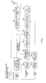
- FIG.2 is a block diagram showing the main configuration of the radio transmitting apparatus according to Embodiment 1 of the present invention.
- the radio transmitting apparatus is used as a base station in a mobile communication system.
- the radio transmitting apparatus has allocation resource table determining section 101, encoding sections 102-1 and 102-2, retransmission controlling section 103, modulating sections 104-1 and 104-2, multiplexing section 105, control information multiplexing section 106, IFFT section 107, CP inserting section 108, radio transmitting section 109 and antenna 110, and these sections perform the following operations.
- Encoding section 102-1 performs error correcting encoding such as turbo encoding on transmission data and outputs the result to retransmission controlling section 103.
- Encoding section 102-2 also performs error correcting encoding such as turbo encoding on control data and outputs the result to modulating section 104-2.
- Retransmission controlling section 103 buffers bits subjected to turbo encoding in an internal memory and controls whether to output a new packet to modulating section 104-1 or output a retransmission packet stored in the internal memory to modulating section 104-1, based on an ACK/NACK signal fed back from the mobile station. Further, retransmission controlling section 103 counts the number of retransmissions and reports the number to multiplexing section 105.
- Modulating section 104-1 performs predetermined modulating processing such as QPSK and 16QAM on a symbol, which is outputted from retransmission controlling section 103 and which is to be multiplexed on a transmission subframe, and outputs the result to multiplexing section 105.
- Modulating section 104-2 performs modulation such as QPSK and 16QAM on encoded data outputted from encoding section 102-2 and outputs the result to control information multiplexing section 106.
- Allocation resource table determining section 101 generates a retransmission allocation resource control signal showing a resource allocation method using moving speed information fed back from the mobile station with reference to an internal data table, and outputs the signal to multiplexing section 105 and encoding section 102-2.
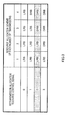
- FIG.3 shows an example of the data table. In this table, the correspondence relationships between the resource allocation schemes (i.e., LRB scheme and DRB scheme) of each number of retransmissions and retransmission allocation resource control signals, are determined in advance.
- allocation resource table determining section 101 outputs retransmission allocation resource control signal #2.
- Multiplexing section 105 allocates modulated data outputted from modulating section 104-1 to a plurality of frequency resources, performs frequency-domain-multiplexing on the transmission data and outputs the multiplexed signal to control information multiplexing section 106.
- multiplexing section 105 allocates the frequency resources using the CQI information fed back from the mobile station, according to the resource allocation scheme of each number of retransmissions specified by the retransmission allocation resource control signal.
- Control information multiplexing section 106 checks the subframe numbers, and, when a subframe is the head subframe, multiplexes predetermined control information and outputs the multiplexed signal to IFFT section 107.
- IFFT section 107 performs inverse fast Fourier transform (IFFT) processing on the multiplexed signal to generate an OFDM symbol converted to the time domain and outputs the symbol to CP inserting section 108.
- IFFT inverse fast Fourier transform
- CP inserting section 108 duplicates the rear part of the OFDM symbol outputted from IFFT section 107 as a CP, inserts the CP to the head part and outputs the result signal to radio transmitting section 109.
- Radio transmitting section 109 performs predetermined radio transmission processing such as D/A conversion and power amplification on the signal after the CP is inserted, generates a radio signal and transmits the signal via antenna 110.
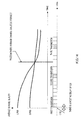
- FIG.4 illustrates the basic operation of allocation resource table determining section 101.
- the graph in the figure shows the calculated average channel quality of each band when the LRB scheme or DRB scheme is used.
- Allocation resource table determining section 101 specifies from this graph, the number of transmissions where the average channel quality in the band of the DRB scheme is higher than the average channel quality in a band of the LRB scheme. That is, the position of the boundary where the frequency diversity effect exceeds the frequency scheduling effect, is calculated.
- FIG.4 shows the boundary upon move at medium speed. The number of transmissions that follows the boundary in the time domain becomes the number of transmissions at which the resource allocation scheme should be switched. Therefore, allocation resource table determining section 101 reports the retransmission allocation resource control signal determined based on the table shown in FIG.3 , to multiplexing section 105 and encoding section 102-2 as control information.
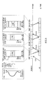
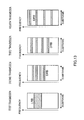
- FIG.5 illustrates the signal transmitted by the above operation from the radio transmitting apparatus according to the present embodiment.
- "2" is assumed to be selected as the retransmission allocation resource control signal.
- the LRB is selected as the resource allocation scheme based on the CQI fed back from the mobile station, and the RB with the best received quality is allocated to the transmission data according to the LRB scheme.
- a retransmission allocation resource control signal, LRB number and DRB number together with an MCS (Modulation and Coding Scheme) and coding rate are multiplexed on a control channel SCCH.
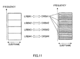
- the LRB number and DRB number refer to the numbers for distinguishing between four resource allocation methods according to the resource allocation scheme, for example, LRB#1 to #4 when the resource allocation scheme is the LRB scheme, and, more specifically, show the position of an RB to which the transmission data is actually allocated.
- the retransmission allocation resource control signal shows "2," and therefore multiplexing section 105 allocates the transmission data to the same RB using the same resource allocation scheme (LRB) as in the first transmission.
- LLB resource allocation scheme
- the retransmission allocation resource control signal shows "2," and therefore multiplexing section 105 switches to a different resource allocation scheme from the first transmission and the second transmission, and allocates the transmission data to the RB using the DRB scheme.
- the radio transmitting apparatus uses the LRB scheme as the resource allocation scheme upon the first transmission in retransmission control of transmission data, and switches the resource allocation scheme to the DRB scheme during retransmissions in a plurality of retransmissions, to perform transmission. Further, the switching timing is changed adaptively based on the moving speed of the mobile station.
- radio receiving apparatus mobile station
- basestation basestation
- FIG.7 is a block diagram showing the main configuration of the radio receiving apparatus according to the present embodiment.
- the radio receiving apparatus has antenna 151, radio receiving section 152, CP removing section 153, FFT section 154, channel compensating section 155, control information demultiplexing section 156, demodulating section 157, decoding section 158, data extracting section 159, demodulating section 160, combining section 161, decoding section 162 and retransmission controlling section 163, and the sections perform the following operations.
- Radio receiving section 152 performs predetermined radio receiving processing such as down-conversion and A/D conversion on a signal received via antenna 151 and outputs the obtained baseband signal to CP removing section 153.
- CP removing section 153 removes the CP added to the received signal and outputs the signal after the CP is removed to FFT section 154.
- FFT section 154 performs fast Fourier transform (FFT) processing on a per OFDM symbol basis,to convert the received signal to a frequency domain and outputs the frequency domain signal to channel compensating section 155.
- FFT fast Fourier transform
- Channel compensating section 155 performs channel estimation from the received pilot symbol of the frequency domain signal, compensates for the received signal using the obtained channel estimation value and outputs the compensated signal to control information demultiplexing section 156. Further, channel compensating section 155 measures the moving speed and CQI from the channel estimation value and outputs them separately.
- Control information demultiplexing section 156 demultiplexes the symbols on which control information is multiplexed, from the compensated signal, outputs the symbols on which control information is mapped to demodulating section 157 and outputs the other symbols to data extracting section 159.
- Demodulating section 157 performs predetermined demodulation processing such as QPSK and 16QAM on the symbols on which control information is mapped and outputs the demodulated signal to decoding section 158.
- Decoding section 158 performs decoding processing such as turbo decoding on the demodulated signal to obtain control data and outputs a retransmission allocation resource control signal, LRB number and DRB number to data extracting section 159.
- Data extracting section 159 extracts a data symbol from the output signal of control information demultiplexing section 156 using the retransmission allocation resource control signal, LRB number, DRB number and the number of retransmissions and outputs the data symbol to demodulating section 160.
- Demodulating section 160 performs predetermined demodulating processing such as QPSK and 16QAM on the extracted data symbol and outputs the demodulated signal to combining section 161 and retransmission controlling section 163.
- combining section 161 When reported from retransmission controlling section 163 that the input signal is a retransmitted packet, combining section 161 combines the buffered received data and currently received data and outputs the combined signal to decoding section 162.
- Decoding section 162 performs decoding processing such as turbo decoding on the signal outputted from combining section 161 and obtains received data.
- the decoded data is also outputted to retransmission controlling section 163.
- Retransmission controlling section 163 performs, for example, a CRC on the decoded data and determines whether this packet has been received erroneously or correctly. When this packet has been received correctly, an ACK signal is fed back to the base station, and, when this packet has been received erroneously, a NACK signal is fedback to the base station as a retransmission request. Further, retransmission controlling section 163 passes the received data to combining section 161. Still further, retransmission controlling section 163 counts the number of retransmissions and passes the number to data extracting section 159.
- FIG.8 illustrates reception processing and reception performance of the radio receiving apparatus according to the present embodiment having the above configuration.
- FIG.8 assumes that "2" is selected as the retransmission allocation resource control signal.
- the first transmission first, by demodulating the control channel SCCH arranged in the head of the subframe, control data is obtained.
- the retransmission allocation resource control signal, LRB number and DRB number included in the control data is acquired and stored in the internal memory.
- the retransmission allocation resource control signal shows "2, " and so data extracting section 159 determines that the resource allocation scheme is the LRB based on the internal table (see FIG. 3 ).
- the RB to which data is actually allocated, is specified from the LRB number inputted separately, and a data symbol is extracted from this RB.
- Demodulating section 160 demodulates data of, for example, QPSK and 16QAM and calculates the likelihood of each bit. This transmission is the first transmission, and so combining section 161 does not perform combining.
- Decoding section 162 performs error correcting decoding of the likelihood of each bit using, for example, turbo decoding.
- Retransmission controlling section 163 performs a CRC check of the decoded data.
- the packet is assumed to be received erroneously. Therefore, retransmission controlling section 163 feeds back a NACK signal to the base station as a retransmission request and buffers the likelihood of each bit.
- the retransmission allocation resource control signal shows "2," and therefore data extracting section 159 determines that the resource allocation scheme of this time is also the LRB, distinguishes the RB on which a data symbol is multiplexed, based on the LRB number inputted separately, and extracts the data symbol. Packets are decoded in the same way as in the first transmission and combined. Also in this case, the packets are assumed to be received erroneously. Therefore, retransmission controlling section 163 feeds back a NACK signal to the base station as a retransmission request and buffers the likelihood of each bit.
- the retransmission allocation resource control signal shows "2," and therefore data extracting section 159 determines that the resource allocation scheme of this time is the DRB, distinguishes the RB on which a data symbol is multiplexed, based on the LRB number inputted separately, and extracts the data symbol. Packets are decoded in the same way as in the first and second transmission and combined. Here, the packets are assumed to be received correctly. Therefore, retransmission controlling section 163 feeds back an ACK signal to the base station.
- the difference between the received quality reported in the CQI and the actual real-time received quality is large.
- the LRB scheme is used as the resource allocation scheme in the first and second transmission
- the DRB scheme is used in the third transmission which is during retransmissions. Therefore, in the third transmission, the frequency diversity gain can be obtained, and so the received quality does not degrade substantially.
- the radio receiving apparatus can improve reception performance by receiving a signal transmitted from the radio transmitting apparatus according to the present embodiment and performing the above operations.
- the radio transmitting apparatus switches the resource allocation scheme from the LRB to the DRB during retransmissions according to a predetermined rule. Therefore, even if the channel environment fluctuates and frequency allocation performed using the first transmission as a reference becomes inadequate upon retransmission, it is possible to obtain a diversity effect by using the DRB scheme and prevent degradation of received quality.
- the present embodiment is characterized in that the resource allocation scheme is switched from the LRB to the DRB at a timing at which the frequency scheduling effect starts decreasing.
- the resource allocation scheme switching timing (specifically, the number of transmissions or the number of retransmissions) is adjusted according to the moving speed of the mobile station. Therefore, even when the channel state fluctuates variously, it is possible to respond to this and prevent degradation of reception performance.
- the table shown in FIG.10 as the table for determining the resource allocation scheme switching timing.
- this table in addition to the resource allocation schemes and modulation schemes, coding rates are associated. If the moving speed of the mobile station is determined, a "packet form report signal" matching the parameters is selected.
- the resource allocation scheme is shifted to the DRB scheme with a smaller number of retransmissions. Therefore, it is possible to obtain a higher frequency diversity effect. That is, based on the fact that a higher frequency diversity effect can be obtained when the coding rate is lower, the reception performances are improved by switching the resource allocation scheme to the DRB scheme earlier when the coding rate is lower.
- FIG.11 shows an example of the correspondence between the LRB numbers and DRB numbers.
- the following resource allocation method when retransmissions are performed a plurality of times after switching to the DRB scheme, the following resource allocation method can be applied.
- FIG.12 shows an example of the resource allocation method of the DRB scheme.
- the position where frequency resource is allocated in the DRB scheme is changed per number of transmissions. For example, transmission data is allocated to different DRB numbers between the second transmission and the third transmission. By this means, it is possible to obtain a higher frequency diversity effect.
- FIG.13 shows another variation of the resource allocation method of the DRB scheme.
- resource is allocated to the frequency position in the range near the range for the LRB scheme.
- frequency resources are distributed in a greater range in the DRB scheme.
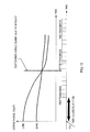
- FIG.14 and FIG.15 show the average channel quality which fluctuates by a difference of the CQI reception timing.
- the time when the performance curve of the LRB scheme intersects with the performance curve of the DRB scheme (the position where the average channel qualities intersect), that is, the time when the performances of the LRB scheme and the DRB scheme switch, is set as the switching timing.
- the switching timing becomes optimum, so that it is possible to prevent degradation of the reception performance. It is alsopossible to adopt a configuration where this control is performed based on BLER (outer loop control) in the mobile station, that is, ACK/NACK information transmitted from the mobile station to the base station.
- BLER outer loop control
- the base station switches the resource allocation scheme from the LRB to the DRB during retransmissions according to the predetermined table.
- Embodiment 2 a configuration will be described where the resource allocation scheme switching timing is reported in real time and the packet combining gain is obtained even when the channel environment fluctuates.
- the basic configuration of the radio transmitting apparatus according to the present embodiment is the same as the radio transmitting apparatus (see FIG.2 ) described in Embodiment 1, and so a block diagram, for example, will not be shown.
- allocation resource table determining section 101 outputs "the number of retransmissions for reallocation" instead of a "retransmission allocation resource control signal.” This number of retransmissions for reallocation is used to issue a command to switch the resource allocation scheme when the number of transmissions is equivalent to the number of retransmissions for reallocation.
- FIG.16 illustrates a signal transmitted from the radio transmitting apparatus according to the present embodiment.
- the number of retransmissions for reallocation is assumed to be set "2.”
- the LRB is selected as the resource allocation scheme based on the CQI fed back from the mobile station, and the RB with the best received quality is allocated to transmission data, according to the LRB scheme.
- the number of retransmissions for reallocation is multiplexed on the control channel SCCH and transmitted.
- the number of retransmissions for reallocation is "2," and so multiplexing section 105 allocates the transmission data to the same band (RB) as the first transmission using the same resource allocation scheme (LRB) as in the first transmission.
- the number of retransmissions for reallocation is "2," and so multiplexing section 105 switches to a different resource allocation scheme from the first transmission and the second transmission, reallocates frequency resource and allocates the transmission data to a different RB from the first and second transmission.
- the DRB number used is reported to the base station via the SCCH.
- the radio transmitting apparatus switches the resource allocation scheme from the LRB scheme to the DRB scheme during retransmissions. Therefore, it is possible to reduce control information, increase the combining gain of the retransmission packet by performing reallocation when the frequency scheduling effect upon the first transmission deteriorates, and improve reception performance.
- the mobile station can recognize the DRB number to be used from the past LRB number without a report of the DRB number.
- the radio communication system, radio transmitting apparatus and retransmission method according to the present invention are not limited by the above embodiments, and can be implemented with various modifications.
- the present invention is also applicable to uplink communication from the mobile station to the base station.
- uplink communication scheme other than OFDM, communication schemes such as DFT-OFDM and SC-FDMA, which use the resource allocation schemes of the LRB scheme and DRB scheme, can be applied.
- the radio transmitting apparatus determines the resource allocation scheme switching timing or the timing for re-scheduling and reports the result upon the first transmission
- the present invention may adopt a configuration where the radio transmitting apparatus switches the resource allocation scheme or performs re-scheduling after receiving a request for switching the resource allocation scheme or request for re-scheduling from the radio receiving apparatus (mobile station). That is, it is also possible to adopt a configuration where, only when the received quality of the allocated band degrades and the resource allocation scheme needs to be switched from the LRB to the DRB, the mobile station requests the base station to, for example, switch the scheme using uplink.
- the mobile station can take the initiative of, for example, switching the resource allocation scheme, so that, even when the channel fluctuates significantly, it is possible to respond to this in a simple manner.
- a request signal (flag) thereof instead of adding bits to the uplink control channel, a CQI feedback signal from the mobile station may be substituted. That is, when the CQI is fed back from the mobile station, it is possible to decide that there is a request for, for example, switching the resource allocation scheme, and perform switching. By this means, it is possible to request for, for example, switching without transmitting new control information separately. Further, the CQI only needs to include at least average received quality information of the entire band for the DRB.
- a rule is set that normally only a NACK signal is fed back, and by feeding back the NACK signal and CQI when the received quality of the mobile station degrades, the mobile station requests the base station to perform re-scheduling.
- the NACK and CQI By transmitting the NACK and CQI using the same coding block, it is possible to avoid the situation where only the CQI becomes an error.
- the present description has been described focusing on synchronous HARQ, the present invention is not limited to this and can be applied to asynchronous HARQ, that is, HARQ that transmits control information other than the allocation resource information on a per retransmission basis.
- control information is reported using the SCCH
- a control channel with other names such as a dedicated control channel may be used.
- the LRB is a channel for performing frequency scheduling transmission and also referred to as a localized channel.
- the DRB is a channel for performing frequency diversity transmission and also referred to as a distributed channel.
- the LRB is normally allocated in subband units or in units of a plurality of consecutive subcarriers.
- the DRB is configured with a plurality of subcarriers distributed over a wide band of the OFDM symbol, or defined by an FH (Frequency Hopping) pattern.
- the DRB may also be referred to as an "Intra-TTI frequency hopping.”
- the DRB may be realized by frequency interleaving.
- the radio transmitting apparatus can be mounted on a communication terminal apparatus and base station apparatus in a mobile communication system, so that it is possible to provide a communication terminal apparatus, base station apparatus and mobile communication system that have the same operational effects as described above.
- the present invention can also be implemented by software.
- the functions similar to those of the radio transmitting apparatus according to the present invention can be realized by describing an algorithm of the retransmission method according to the present invention in a programming language, storing this program in a memory and causing an information processing section to execute the program.
- Each function block used to explain the above-described embodiments may be typically implemented as an LSI constituted by an integrated circuit. These may be individual chips or may partially or totally contained on a single chip.
- each function block is described as an LSI, but this may also be referred to as "IC”, “system LSI”, “super LSI”, “ultra LSI” depending on differing extents of integration.
- circuit integration is not limited to LSI's, and implementation using dedicated circuitry or general purpose processors is also possible.
- LSI manufacture utilization of a programmable FPGA (Field Programmable Gate Array) or a reconfigurable processor in which connections and settings of circuit cells within an LSI can be reconfigured is also possible.
- FPGA Field Programmable Gate Array
- the radio transmitting apparatus and retransmission method according to the present invention are applicable to, for example, a communication terminal apparatus and base station apparatus in a mobile communication system.
Applications Claiming Priority (2)
| Application Number | Priority Date | Filing Date | Title |
|---|---|---|---|
| JP2006076994 | 2006-03-20 | ||
| PCT/JP2007/055685 WO2007108473A1 (ja) | 2006-03-20 | 2007-03-20 | 無線通信システム、無線送信装置、および再送方法 |
Publications (1)
| Publication Number | Publication Date |
|---|---|
| EP1990942A1 true EP1990942A1 (de) | 2008-11-12 |
Family
ID=38522500
Family Applications (1)
| Application Number | Title | Priority Date | Filing Date |
|---|---|---|---|
| EP07739128A Withdrawn EP1990942A1 (de) | 2006-03-20 | 2007-03-20 | Funkkommunikationssystem, funkübertragungsgerät und wiederübertragungsverfahren |
Country Status (4)
| Country | Link |
|---|---|
| US (1) | US8774107B2 (de) |
| EP (1) | EP1990942A1 (de) |
| JP (1) | JP5061095B2 (de) |
| WO (1) | WO2007108473A1 (de) |
Cited By (5)
| Publication number | Priority date | Publication date | Assignee | Title |
|---|---|---|---|---|
| WO2009157859A3 (en) * | 2008-06-26 | 2010-03-11 | Telefonaktiebolaget L M Ericsson (Publ) | Error control in multi-carrier wireless systems |
| US8068011B1 (en) | 2010-08-27 | 2011-11-29 | Q Street, LLC | System and method for interactive user-directed interfacing between handheld devices and RFID media |
| WO2012012128A3 (en) * | 2010-06-30 | 2012-03-29 | Alcatel Lucent | Harq operating point adaptation in communications |
| US8705462B2 (en) | 2007-10-01 | 2014-04-22 | Ntt Docomo, Inc. | User equipment terminal, base station and control information transmission method |
| EP2104370B1 (de) * | 2007-01-09 | 2020-08-12 | Sun Patent Trust | Funkkommunikations-basisstationsvorrichtung und steuersignalzuweisungsverfahren dafür |
Families Citing this family (16)
| Publication number | Priority date | Publication date | Assignee | Title |
|---|---|---|---|---|
| JP4916389B2 (ja) * | 2007-06-19 | 2012-04-11 | 株式会社エヌ・ティ・ティ・ドコモ | 無線通信制御方法、基地局装置、およびユーザ装置 |
| US8428606B1 (en) | 2007-08-31 | 2013-04-23 | Apple Inc. | Communicating control information including an index |
| CN101874370B (zh) * | 2007-11-26 | 2014-04-16 | 夏普株式会社 | 无线通信系统、无线发送装置、无线通信方法以及程序 |
| JP5392667B2 (ja) * | 2008-03-05 | 2014-01-22 | シャープ株式会社 | 通信システム、送信装置、受信装置及び通信方法 |
| US8570910B2 (en) * | 2008-06-20 | 2013-10-29 | Panasonic Corporation | Wireless transmission apparatus and wireless transmission method |
| JP5115369B2 (ja) * | 2008-07-09 | 2013-01-09 | 富士通株式会社 | 基地局装置、通信システムおよびチャネル割当方法 |
| US8737319B2 (en) * | 2008-12-15 | 2014-05-27 | Samsung Electronics Co., Ltd. | Method and apparatus for reducing map overhead in a broadand wireless communication system |
| US20110317563A1 (en) * | 2009-03-03 | 2011-12-29 | Nec Corporation | Communication device and resource reallocation method in radio communications system |
| KR101307630B1 (ko) * | 2009-03-23 | 2013-09-12 | 후지쯔 가부시끼가이샤 | 무선 통신 시스템, 기지국 장치, 단말 장치, 및 무선 통신 시스템에 있어서의 무선 통신 방법 |
| JP2010278887A (ja) * | 2009-05-29 | 2010-12-09 | Panasonic Corp | 基地局装置、端末装置、無線通信システム及び送信方法 |
| JP4917140B2 (ja) * | 2009-10-08 | 2012-04-18 | 株式会社エヌ・ティ・ティ・ドコモ | 無線通信システム、無線送信装置及び無線受信装置 |
| KR101998085B1 (ko) | 2010-12-10 | 2019-07-09 | 선 페이턴트 트러스트 | 송신방법, 송신장치, 수신방법 및 수신장치 |
| GB2491222B (en) * | 2012-02-29 | 2013-07-10 | Renesas Mobile Corp | Channel quality |
| JP6608057B2 (ja) * | 2016-07-05 | 2019-11-20 | 株式会社日立国際電気 | 無線通信システム、無線通信装置および無線通信方法 |
| US10362574B2 (en) * | 2016-11-18 | 2019-07-23 | Qualcomm Incorporated | Uplink resource allocation techniques for shared radio frequency spectrum |
| WO2023139696A1 (ja) * | 2022-01-19 | 2023-07-27 | 日本電信電話株式会社 | 無線通信システム、無線通信方法、及び無線装置 |
Family Cites Families (12)
| Publication number | Priority date | Publication date | Assignee | Title |
|---|---|---|---|---|
| GB2288949B (en) * | 1994-04-22 | 1998-04-08 | Motorola Ltd | Communications system |
| JP2002009734A (ja) * | 2000-06-27 | 2002-01-11 | Denso Corp | Ofdm方式を用いた通信システム |
| EP1255368A1 (de) * | 2001-04-30 | 2002-11-06 | Siemens Information and Communication Networks S.p.A. | Verfahren zur Verbindungsanpassung in verbesserten zellularen Kommunikationssystemen die mehrere Modulationen und Kanalkodierungsarten verwenden |
| US20030039226A1 (en) * | 2001-08-24 | 2003-02-27 | Kwak Joseph A. | Physical layer automatic repeat request (ARQ) |
| US7126996B2 (en) * | 2001-12-28 | 2006-10-24 | Motorola, Inc. | Adaptive transmission method |
| US20060233282A1 (en) * | 2003-05-14 | 2006-10-19 | Matsushita Electric Industrial Co., Ltd. | Modulation method, modulation apparatus, demodulation apparatus, and radio communication system |
| KR101133632B1 (ko) * | 2003-07-31 | 2012-04-10 | 파나소닉 주식회사 | 무선 송신 장치 및 변조 방식의 선택 방법 |
| KR20050083104A (ko) * | 2004-02-21 | 2005-08-25 | 삼성전자주식회사 | 이동통신 시스템에서 기지국의 섹터 운용 방법 및 그 장치 |
| KR100929103B1 (ko) * | 2004-08-17 | 2009-11-30 | 삼성전자주식회사 | 직교주파수다중분할 이동통신시스템에서 고속 순방향 패킷 데이터 서비스를 지원하기 위한 주파수 할당 장치 및 방법 |
| KR100754617B1 (ko) * | 2004-10-11 | 2007-09-05 | 삼성전자주식회사 | 직교 주파수 분할 다중화 통신 시스템에서 피크대 평균전력비를 최소화시키기 위한 장치 및 방법 |
| US20060209970A1 (en) * | 2005-01-11 | 2006-09-21 | Emmanuel Kanterakis | Adaptive transmission rate communication system |
| US7423997B2 (en) * | 2005-10-04 | 2008-09-09 | Motorola, Inc. | Group scheduling in wireless communication systems |
-
2007
- 2007-03-20 US US12/293,516 patent/US8774107B2/en active Active
- 2007-03-20 EP EP07739128A patent/EP1990942A1/de not_active Withdrawn
- 2007-03-20 WO PCT/JP2007/055685 patent/WO2007108473A1/ja active Application Filing
- 2007-03-20 JP JP2008506310A patent/JP5061095B2/ja active Active
Non-Patent Citations (1)
| Title |
|---|
| See references of WO2007108473A1 * |
Cited By (8)
| Publication number | Priority date | Publication date | Assignee | Title |
|---|---|---|---|---|
| EP2104370B1 (de) * | 2007-01-09 | 2020-08-12 | Sun Patent Trust | Funkkommunikations-basisstationsvorrichtung und steuersignalzuweisungsverfahren dafür |
| US8705462B2 (en) | 2007-10-01 | 2014-04-22 | Ntt Docomo, Inc. | User equipment terminal, base station and control information transmission method |
| WO2009157859A3 (en) * | 2008-06-26 | 2010-03-11 | Telefonaktiebolaget L M Ericsson (Publ) | Error control in multi-carrier wireless systems |
| WO2012012128A3 (en) * | 2010-06-30 | 2012-03-29 | Alcatel Lucent | Harq operating point adaptation in communications |
| US8621308B2 (en) | 2010-06-30 | 2013-12-31 | Alcatel Lucent | HARQ operating point adaptation in communications |
| US8068011B1 (en) | 2010-08-27 | 2011-11-29 | Q Street, LLC | System and method for interactive user-directed interfacing between handheld devices and RFID media |
| US8395486B2 (en) | 2010-08-27 | 2013-03-12 | Q Street, LLC | System and method for interactive user-directed interfacing between handheld devices and RFID media |
| US9858455B2 (en) | 2010-08-27 | 2018-01-02 | Q Street, LLC | System and method for interactive user-directed interfacing between handheld devices and RFID media |
Also Published As
| Publication number | Publication date |
|---|---|
| WO2007108473A1 (ja) | 2007-09-27 |
| JP5061095B2 (ja) | 2012-10-31 |
| JPWO2007108473A1 (ja) | 2009-08-06 |
| US20090168711A1 (en) | 2009-07-02 |
| US8774107B2 (en) | 2014-07-08 |
Similar Documents
| Publication | Publication Date | Title |
|---|---|---|
| US8774107B2 (en) | Radio communication system, radio transmission apparatus, and retransmission method | |
| US11765726B2 (en) | Radio transmission device and radio transmission method | |
| US8649333B2 (en) | Radio communication system, radio transmission apparatus, and resource allocation method | |
| US10819411B2 (en) | Integrated circuit for CQI reporting in wireless communication | |
| KR101302633B1 (ko) | 이동국 및 기지국 | |
| US8320356B2 (en) | Wireless communication apparatus and wireless communication method | |
| EP1901460A1 (de) | Basisstationsgerät und drahtloses kommunikationsverfahren für mehrträger-kommunikation | |
| JP5934700B2 (ja) | 中継局、基地局、送信方法、及び受信方法 | |
| KR20100083440A (ko) | 다중 반송파 전송 방식을 사용하는 무선 통신 시스템에서의상향링크 제어 정보 송신 장치 및 방법 |
Legal Events
| Date | Code | Title | Description |
|---|---|---|---|
| PUAI | Public reference made under article 153(3) epc to a published international application that has entered the european phase |
Free format text: ORIGINAL CODE: 0009012 |
|
| 17P | Request for examination filed |
Effective date: 20080917 |
|
| AK | Designated contracting states |
Kind code of ref document: A1 Designated state(s): AT BE BG CH CY CZ DE DK EE ES FI FR GB GR HU IE IS IT LI LT LU LV MC MT NL PL PT RO SE SI SK TR |
|
| RAP1 | Party data changed (applicant data changed or rights of an application transferred) |
Owner name: PANASONIC CORPORATION |
|
| DAX | Request for extension of the european patent (deleted) | ||
| STAA | Information on the status of an ep patent application or granted ep patent |
Free format text: STATUS: THE APPLICATION IS DEEMED TO BE WITHDRAWN |
|
| 18D | Application deemed to be withdrawn |
Effective date: 20121002 |