EP1990643A1 - Systeme, Verfahren und Vorrichtung zur Messung der Kapazität in einem Stator Teil - Google Patents
Systeme, Verfahren und Vorrichtung zur Messung der Kapazität in einem Stator Teil Download PDFInfo
- Publication number
- EP1990643A1 EP1990643A1 EP08155856A EP08155856A EP1990643A1 EP 1990643 A1 EP1990643 A1 EP 1990643A1 EP 08155856 A EP08155856 A EP 08155856A EP 08155856 A EP08155856 A EP 08155856A EP 1990643 A1 EP1990643 A1 EP 1990643A1
- Authority
- EP
- European Patent Office
- Prior art keywords
- capacitance
- contacts
- sensed
- output device
- operable
- Prior art date
- Legal status (The legal status is an assumption and is not a legal conclusion. Google has not performed a legal analysis and makes no representation as to the accuracy of the status listed.)
- Withdrawn
Links
- 238000000034 method Methods 0.000 title claims abstract description 17
- 239000000463 material Substances 0.000 claims abstract description 52
- 239000004020 conductor Substances 0.000 claims abstract description 28
- 238000004891 communication Methods 0.000 claims description 5
- 229920001971 elastomer Polymers 0.000 claims description 4
- 229920002379 silicone rubber Polymers 0.000 claims description 3
- 239000000806 elastomer Substances 0.000 claims description 2
- 239000006260 foam Substances 0.000 claims description 2
- 239000011888 foil Substances 0.000 claims description 2
- 239000007769 metal material Substances 0.000 claims description 2
- 239000004945 silicone rubber Substances 0.000 claims description 2
- 229920001296 polysiloxane Polymers 0.000 claims 1
- 238000005259 measurement Methods 0.000 description 35
- 238000009413 insulation Methods 0.000 description 10
- 238000004804 winding Methods 0.000 description 8
- 239000000523 sample Substances 0.000 description 6
- 230000008859 change Effects 0.000 description 5
- 230000000875 corresponding effect Effects 0.000 description 5
- 238000012360 testing method Methods 0.000 description 4
- 239000003990 capacitor Substances 0.000 description 3
- 238000001514 detection method Methods 0.000 description 3
- 238000010586 diagram Methods 0.000 description 3
- 238000007689 inspection Methods 0.000 description 3
- 239000007788 liquid Substances 0.000 description 3
- 238000013480 data collection Methods 0.000 description 2
- 238000012986 modification Methods 0.000 description 2
- 230000004048 modification Effects 0.000 description 2
- 230000008569 process Effects 0.000 description 2
- 230000009467 reduction Effects 0.000 description 2
- XUIMIQQOPSSXEZ-UHFFFAOYSA-N Silicon Chemical compound [Si] XUIMIQQOPSSXEZ-UHFFFAOYSA-N 0.000 description 1
- BQCADISMDOOEFD-UHFFFAOYSA-N Silver Chemical compound [Ag] BQCADISMDOOEFD-UHFFFAOYSA-N 0.000 description 1
- 230000009471 action Effects 0.000 description 1
- 230000009118 appropriate response Effects 0.000 description 1
- 230000008901 benefit Effects 0.000 description 1
- 230000006835 compression Effects 0.000 description 1
- 238000007906 compression Methods 0.000 description 1
- 238000007796 conventional method Methods 0.000 description 1
- 238000001816 cooling Methods 0.000 description 1
- 230000002596 correlated effect Effects 0.000 description 1
- 230000007547 defect Effects 0.000 description 1
- 238000012423 maintenance Methods 0.000 description 1
- 238000000691 measurement method Methods 0.000 description 1
- 238000012544 monitoring process Methods 0.000 description 1
- 230000010363 phase shift Effects 0.000 description 1
- 238000012545 processing Methods 0.000 description 1
- 238000011084 recovery Methods 0.000 description 1
- 229910052710 silicon Inorganic materials 0.000 description 1
- 239000010703 silicon Substances 0.000 description 1
- 229910052709 silver Inorganic materials 0.000 description 1
- 239000004332 silver Substances 0.000 description 1
- 238000007619 statistical method Methods 0.000 description 1
Images

Classifications
-
- G—PHYSICS
- G01—MEASURING; TESTING
- G01R—MEASURING ELECTRIC VARIABLES; MEASURING MAGNETIC VARIABLES
- G01R31/00—Arrangements for testing electric properties; Arrangements for locating electric faults; Arrangements for electrical testing characterised by what is being tested not provided for elsewhere
- G01R31/34—Testing dynamo-electric machines
-
- G—PHYSICS
- G01—MEASURING; TESTING
- G01R—MEASURING ELECTRIC VARIABLES; MEASURING MAGNETIC VARIABLES
- G01R1/00—Details of instruments or arrangements of the types included in groups G01R5/00 - G01R13/00 and G01R31/00
- G01R1/02—General constructional details
- G01R1/06—Measuring leads; Measuring probes
- G01R1/067—Measuring probes
- G01R1/06794—Devices for sensing when probes are in contact, or in position to contact, with measured object
-
- G—PHYSICS
- G01—MEASURING; TESTING
- G01R—MEASURING ELECTRIC VARIABLES; MEASURING MAGNETIC VARIABLES
- G01R31/00—Arrangements for testing electric properties; Arrangements for locating electric faults; Arrangements for electrical testing characterised by what is being tested not provided for elsewhere
- G01R31/50—Testing of electric apparatus, lines, cables or components for short-circuits, continuity, leakage current or incorrect line connections
- G01R31/52—Testing for short-circuits, leakage current or ground faults
Definitions
- the invention relates generally to electrical power generators, and more particularly, to systems, methods, and apparatus for measuring capacitance in a stator component such as a stator bar of an electrical power generator.
- stator windings also known as armature windings
- armature windings can include a series of stator windings.
- Each stator winding can include a series of conductive or stator bars wrapped in one or more layers of insulation.
- the insulation can confine the current in the stator bars, and can prevent the arcing of electrical current between windings. Furthermore, the insulation can shield the stator bars against stray objects that could electrically short the bars. If the insulating properties of the insulation degrades over time or becomes damp due to excess moisture from a cooling leak, voltage arcs may jump from the stator bars through degraded regions of the insulation and cause electrical shorts that may harm people and/or equipment. Early detection of such leaks can minimize or prevent harm to people and/or equipment.
- stator windings in particular, the stator bar insulation
- maps of the stator windings can be created to track and monitor different physical characteristics, such as temperature or other physical characteristics. These maps can assist an operator or testing personnel in identifying failures or defects in the stator windings or stator bars.
- the failure to detect moisture in the stator windings and stator bards can lead to dangerous electrical shorts, such as "phase to ground faults" or "phase to phase faults".
- a capacitance map can include a display of capacitance measurements of each of the stator bars.
- each capacitance measurement can be measured at two locations along the stator bar, with one measurement at each end of the generator.
- statistical analysis of the collected data can be conducted during or after data collection to filter outlier-type or false negative data based on a predetermined standard.
- data collection using conventional techniques and devices may be prone to error.
- the conventional probe can be mounted to a stator bar wherein the probe is in physical contact with the stator bar. In some instances, variations or imperfections in the surface area of the probe can cause noise in the capacitance measurements.
- gaps between the probe and the surface of the stator bar or insulated stator bar can cause noise in the capacitance measurements.
- probe misalignment can cause noise in the capacitance measurements.
- noise in the capacitance measurements can affect the quality of the collected data.
- stator monitoring systems and methods there is a need for improved stator monitoring systems and methods. There is also a need for systems, methods, and apparatus to collect capacitance data from a stator component. There is also a need for systems, methods, and apparatus for measuring capacitance in a stator component.
- Embodiments of the invention can address some or all of the needs described above. Embodiments of the invention are directed generally to systems, methods, and apparatus for measuring capacitance in a stator component such as a stator bar.
- a system for measuring capacitance can include an output device operable to measure capacitance in an object.
- the system can include at least three contacts, wherein the contacts can be simultaneously mounted to an object to be sensed.
- the system can include at least one conductive material operable to mount to the object to be sensed.
- the system can include a compressible material adjacent to at least some of the at least three contacts and the at least one conductive material, wherein the compressible material can be compressed to permit the contacts to simultaneously contact the object to be sensed, and wherein the output device can output a measure of capacitance associated with the object.
- a method for measuring capacitance can include providing a capacitance measuring device.
- Providing a capacitance measuring device can comprise providing a device comprising an output device operable to output an indication associated with capacitance of an object.
- providing a capacitance measuring device can comprise providing a device comprising at least three contacts operable to mount to an object to be sensed.
- providing a capacitance measuring device can comprise providing a device comprising at least one conductive material operable to mount to the object to be sensed.
- providing a capacitance measuring device can comprise providing a device comprising a compressible material disposed adjacent to at least some of the at least three contacts and the at least one conductive material, wherein the compressible material can be compressed to permit at least some of the contacts to simultaneously contact the object.
- the method can also include positioning the capacitance measuring device adjacent the object.
- the method can include compressing the compressible material against the object, wherein at least some of the contacts simultaneously contact the object, and observing an output from the output device, wherein the output is associated with the capacitance of the object.
- a system for measuring capacitance can include at least one output device operable to measure capacitance in an object to be sensed. Furthermore, the system can include a first paddle and a second paddle. Each paddle can include at least one contact, wherein the at least one contact is in communication with the at least one output device. Each paddle can also include a conductive material operable to mount to the object to be sensed. In addition, each paddle can include a compressible material adjacent to the at least one contact and the conductive material, wherein the compressible material can be compressed to permit the at least one contact to contact the object to be sensed, wherein the output device can output a measure of capacitance associated with at least one capacitance component associated with each paddle.
- Some or all of the embodiments of the invention can provide some or all of the following aspects: (1) Improved capacitance measurements and data; (2) lower moisture detection thresholds for generator capacitance maps, thus facilitating early detection of leaking stator bars; (3) relatively faster cycle times for testing and analysis; (4) relatively lower equipment costs for inspections and testing; and (5) relatively lower maintenance costs for inspection and testing equipment.
- Embodiments of the invention such as the example system and apparatus 100 shown in FIGs. 1 and 2 , and the example system 200 shown in FIG. 3 , can be implemented with a power generator with one or more stator components or stator bars.
- the example system and apparatus 100 of FIGs. 1 and 2 is a paddle-type device operable for measuring capacitance in an object, such as a stator component or stator bar.
- an output device such as a capacitance meter or multimeter
- FIG. 1 is a perspective view of the example system and apparatus 100
- FIG. 2 illustrates a side view of the system and apparatus 100 in FIG. 1 mounted to a stator component, such as a stator bar.
- a system and apparatus 100 can include a series of contacts 102, 104, 106, a mounting device 108, at least one compressible material 110, and a conductive material 112.
- the example system and apparatus 100 of FIGs. 1 and 2 can be mounted to an object to be sensed, such as a stator component or stator bar 114 shown in FIG. 2 .
- the system and apparatus 100 can be mounted to other devices in a variety of environments where capacitance measurements are desired.
- the contacts 102, 104, 106 can be, for example, a series of pressure switches capable of being closed when a predefined amount of force or pressure is applied to each switch.
- the contacts 102, 104, 106 can be a series of pressure sensors mounted on respective blocks, wherein the respective blocks can mount between the sensors and the mounting device 108, and the sensors are capable of being activated when a predefined amount of force or pressure is applied to each sensor.
- the contacts 102, 104, 106 can be a series of blocks for mounting between the mounting device 108 and the object to be sensed.
- the contacts 102, 104, 106 are operable to mount to an object to be sensed, such as a stator bar similar to that shown as 114 in FIG. 2 , and when actuated or activated, the contacts 102, 104, 106 can form a closed loop electrical circuit.
- the object to be sensed can be an insulated stator bar.
- the contacts 102, 104, 106 are blocks, the simultaneous contact of the blocks 102, 104, 106 with the object to be sensed can form a similar closed loop electrical circuit.
- the contacts 102, 104, 106 are operable to communicate with an output device, such as a 208 in FIG. 3 .
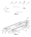
- FIG. 3 An example electrical circuit 200 with switches 202, 204, 206 is shown in FIG. 3 .
- the switches 202, 204, 206 are shown by way of example to demonstrate that the respective contacts 102, 104, 106 can be simultaneously closed when all three contacts 102, 104, 106 are sufficiently close to the object to object to be sensed to form a closed circuit.
- the contacts 102, 104, 106 can be oriented in a triangular and co-planar arrangement.
- the contacts 102, 104, 106 can be electrically connected in series and can be closely associated with the mounting device 108.
- Other suitable contacts can include, but are not limited to, a conductive object, switches, microswitches, and sensors. In other embodiments, fewer or greater numbers of contacts can be used in an apparatus accordance with the invention. In yet other embodiments, the contacts can be arranged in other geometries and configurations.
- the contacts can be configured or arranged to measure a different electrical characteristic, such as a change in impedance, complex impedance, or other physical characteristic of an object.
- changes in the impedance, complex impedance, or other physical characteristics can be used to determine whether a change in the condition of the object being sensed has occurred or is occurring.
- Mounting device 108 can be a paddle-type device or other structure operable to be manually or otherwise physically mounted to an object to be sensed, such as a stator component or stator bar. To facilitate mounting and/or removal by a user or operator, the mounting device 108 may have an associated handle 118.
- the contacts 102, 104, 106 can each mount to one side of the mounting device 108, such that the contacts are in a triangular and co-planar orientation.
- a stepping capacitor 116 can be positioned with respect to or otherwise associated with the handle 118.
- the stepping capacitor 116 can be in electrical communication with the contacts 102, 104, 106, and can be part of the electrical circuit.
- the stepping capacitor 116 can provide a fixed capacitance reference or measure for the system and apparatus 100.
- the fixed capacitance reference or measure can be a threshold, which may be exceeded when all of the contacts 102, 104, 106 are closed, or are sufficiently close to the object being sensed, to complete the associated closed electrical circuit.
- the compressible material 110 can mount to the same side of the mounting device 108 as the contacts 102, 104, 106.
- the compressible material 110 is selected to be a compliant-type material which can be compressed against the object to be sensed. In the example shown, when compressed, the compressible material 110 can minimize the amount of air between the object to be sensed and the system and apparatus 100.
- the compressible material 110 can be oriented with respect to the mounting device 108, such that at least a portion of the compressible material 110 can be disposed between the mounting device 108 and the object to be sensed, such as a stator component or stator bar.
- the compressible material 110 can be uniquely shaped or otherwise formed to permit the contacts 102, 104, 106 to be adjacent to the compressible material 110, and yet permit the contacts 102, 104, 106 to mount directly to an object to be sensed.
- a compressible material can be divided, split, or otherwise apportioned, and each respective portion of compressible material can be disposed between the mounting device 108 and the object to be sensed, such as a stator component or stator bar.
- Suitable compressible materials can include, but are not limited to, a foam, a gel, rubber, silicon gel, silicon rubber, an elastomer, a compliant material, or a spring.
- the compressible material 110 can extend approximately 1 inch (2.2 cm) from the surface of the mounting device 108, and the contacts 102, 104, 106 can extend approximately 0.75 inches (1.65 cm) from the surface of the mounting device 108.
- a conductive material 112 can be mounted to a portion of the compressible material 110.
- the conductive material 112 is relatively thin, and can be substantially disposed between the compressible material 110 and the object to be sensed, such as a stator component or stator bar 114.
- An example conductive material can include, but is not limited to, a foil, a metallic material, or a partially conductive material.
- the compressible material 110 and conductive material 112 can be combined or otherwise integrated. Integrated, for example, can be defined as joining or combining two materials such that the joined or combined materials still maintain at least a portion of the respective properties of the original disjoined or uncombined materials.
- a silicone rubber material and a silver component material can be utilized such that the integrated material is both compressible and conductive.
- the combination of a compressible material 110 and conductive material 112 permits the mounting device 108 to be suitably mounted to an object to be sensed, such as a stator component or stator bar.
- an object to be sensed such as a stator component or stator bar.
- the use of the combination of a compressible material 110 and conductive material 112 can reduce the variations in pressure applied to the surface of the object to be sensed. In other instances, the amount of air between the object to be sensed and the system and apparatus 100 can be minimized to permit the contacts 102, 104, 106 to simultaneously contact the object to be sensed.
- the compressible material can be selected to compress a predetermined amount such that the contacts, for instance 102, 104, 106, can be manipulated to form a closed electrical circuit.
- a user or operator of the system and apparatus 100 can consistently mount the system and apparatus 100 to an object to be sensed by applying a predetermined amount of pressure to the system and apparatus 100 such that the contacts 102, 104, 106 are also consistently and simultaneously mounted to the object.
- each contact 102, 104, 106 can include a mechanical stop positioned between the respective contact 102, 104, 106 and the mounting device 108. Together or individually, the mechanical stops can suitably position and orient the contacts 102, 104, 106 with respect to the compressible material 110 depending on the compression, recovery, and other physical characteristics of the contacts 102, 104, 106 and/or compressible material 110.
- each of the contacts 102, 104, 106 can be associated with a respective indicator, such as a LED or light.
- a respective indicator such as a LED or light.
- each associated indicator can illuminate or otherwise indicate to a user that the respective contact is actuated, activated, or has otherwise received a sufficient amount of force or pressure.
- a single indicator can be associated with all some or all of the contacts 102, 104, 106.
- the associated indicator can illuminate or otherwise indicate to a user that the contacts are actuated, activated, or have otherwise received a sufficient amount of force or pressure.
- the example system 200 in FIG. 3 includes an output device which can be implemented with the system and apparatus 100 shown in FIGs. 1 and 2 .
- the electrical schematic diagram in FIG. 2 illustrates a system operable for measuring capacitance in a stator component, such as a stator bar.
- the system 200 shown can include a series of switches or contacts 202, 204, 206; and an output device 208, such as a capacitance meter or multimeter.
- Contacts 202, 204, 206 can be, for example, a series of pressure switches mounted on a stator component, such as a stator bar.
- the contacts 202, 204, 206 can be similar to the contacts 102, 104, 106 described in FIGs. 1 and 2 .
- Each of the contacts 202, 204, 206 can be operable to communicate with at least one output device, such as 208.
- the contacts 202, 204, 206 can be electrically connected in series to provide a closed electrical circuit with the output device 208 when all three contacts 202, 204, 206 are in the closed position.
- Output device 208 can be a meter, capacitance meter, multimeter, a comparison device, or a display screen operable to output one or more capacitance measurements or otherwise compare capacitance components, measurements or data.
- the output device 208 can be operable to measure one or more capacitance components, such as 210, 212. Measurements of one or more capacitance components 210, 212 can be received by, obtained by, or transmitted to the output device 212, such that capacitance of an object, such as a stator component or stator bar 114, can be measured or compared. An output from the output device 212, such as a signal or other type of indication, can be observed by a user or operator, and an appropriate response or action can be performed if needed.
- Capacitance component 210 can be associated with the actuation or closing of contacts 202, 204, 206.
- Capacitance component 212 designated as C insulation or C bar , is shown associated with an object to be sensed, such as a stator component or stator bar, similar to 114 in FIG. 1 .
- the output device 208 can measure capacitance of an object, such as a stator bar, by comparing the capacitance component (C step or C paddle ) 210 and the capacitance component of the object (C insulation or C bar ) 212. In this manner, a capacitance measurement of an object to be sensed can be obtained.
- fewer or greater numbers of contacts, and other capacitance components can be used in accordance with the invention.
- the contacts can be operable to communicate with a different type of output device, such as a device which can measure a change in the impedance, complex impedance, or other physical characteristic of an object.
- a different type of output device such as a device which can measure a change in the impedance, complex impedance, or other physical characteristic of an object.
- changes in the impedance, complex impedance, or other physical characteristics can be used to determine whether a change in the condition of the object being sensed has occurred or is occurring.
- the output device 212 can include an associated processor, hardware, or software operable to process capacitance components 210, 212.
- a set of computer-executable instructions stored on a computer-readable medium can be adapted to provide thresholding and automatic logging capabilities for the capacitance measurements. Capacitance components or measurements may be collected automatically, particularly when the system and apparatus 100 and/or contacts 102, 104, 106, are suitably positioned, i.e., the contacts 202, 204, 206 are in a closed position creating a closed electrical loop.
- a corresponding step change in the capacitance measured by or otherwise determined by the output device 212 can be identified to confirm the positioning of the contacts 202, 204, 206. In this manner, measurement cycle times can be reduced, and relatively accurate measurements can be collected by a single user or operator without need for additional personnel.
- thresholds can be defined or otherwise set to determine whether a certain capacitance measurement corresponding with the presence of moisture on the object being sensed. For example, a predefined threshold can be set for a particular capacitance measurement corresponding to whether moisture is present on an insulated stator bar for a liquid cooled generator. Various combinations of measurements and/or thresholds can be used to generate a capacitance map for an object such as a stator bar or generator.
- the output device can be operable to output a measurement of impedance or other physical characteristic depending on the configuration of electrical devices in series with the contacts 202, 204, 206. Processing of these alternate measurements by a processor, hardware, or software associated with the output device can include corresponding thresholding and automatic logging capabilities.
- a phase shift measurement technique used to measure impedance or complex impedance can be implemented by a set of computer-readable instructions.
- the system 200 can be implemented with one or more stator components, such as a series of stator bars.
- a series of stator bars 302, 304 can be monitored using a corresponding series of apparatus or paddle-type devices 306, 308, 310, 312, each similar to the apparatus 200 or paddle-type device shown in FIG. 3 .
- Each of the paddles 306, 308, 310, 312 can be functionally connected to at least one output device 314, such as a meter, multimeter, a comparison device, or a display screen operable to output a capacitance measurement.
- Data collected or otherwise obtained by the output device 314 can be used to generate a capacitance map for the series of stator bars 302, 304, or other objects being sensed.
- Those skilled in the art will recognize the devices and techniques needed to generate a capacitance map for the stator bars 302, 304 or other objects.
- the system 300 can utilize one or more conductive strands or wires in lieu of apparatus or paddle-type devices 306, 308, 310, 312.
- the conductive strands or wires can be functionally connected to the output device 314, and capacitance measurements can be obtained in a similar manner as described above.
- a processor, hardware, or software associated with the output device 314 of FIG. 3 can be operable to statistically analyze the capacitance measurements to determine whether any outlier data exists or a predefined threshold is met or unmet.
- a processor such as 316 in FIG. 3 can execute computer-executable instructions 318 stored in a computer-readable medium, such as a memory 320 in FIG. 3 , to process an output associated with the output device 314.
- the computer-readable instructions 318 can be operable to determine or identify outlier data, to determine or identify thresholds and compare data against the thresholds, and to generate a capacitance map based at least in part on the an output associated with the output device 314.
- Outlier data can include, but is not limited to, data that is at least three standard deviations away from the mean.
- a threshold can include, but is not limited to, a predetermined point or measure, and which is assumed to be associated or otherwise correlated with the existence a predefined condition, such as the presence of moisture on the stator bar or object being sensed.
- a threshold can be a capacitance measurement at approximately a three sigma limit.
- a pair of apparatus or paddle-type devices such as 306 and 308, could be used to measure capacitance in a stator component, such as stator bar.
- each apparatus or paddle-type device could be used to measure the capacitance between the pair of apparatus or paddle-type devices.
- one or more conductive strands or wires can be used in lieu of the apparatus or paddle-type devices to measure capacitance.
- the output device such as 314, can be adapted to determine a capacitance measurement based at least in part on the measurements obtained from both of the apparatus or paddle-type devices, or alternatively one or more conductive strands or wires used in combination with apparatus or paddle-type devices.
- an alternative capacitance measuring system to measure capacitance in an object can include at least one output device.
- the system can include a first paddle and a second paddle.
- Each paddle can include at least one contact, wherein the at least one contact is in communication with the output device.
- each paddle can include a conductive material operable to mount to an object to be sensed.
- each paddle can include a compressible material adjacent to the at least one contact and the conductive material, wherein the compressible material can be compressed to permit the at least one contact to contact the object to be sensed.
- the output device can output a measure of capacitance associated with the object or portion of the object to which each paddle is mounted to.
- the system and apparatus 100 shown in FIGs. 1 and 2 , and the systems 200, 300 respectively shown in FIGs. 3 and 4 can be used to measure capacitance in a liquid cooled generator, in particular, one or more stator components or stator bars.
- a method for using the system and apparatus 100 can include providing a system and apparatus 100 as described in FIGs. 1 and 2 .
- the system and apparatus 100 can be mounted to an object to be sensed, such as a stator component or stator bar.
- a compressible material such as 110 in FIGs.
- associated with the system and apparatus 100 can be compressed, wherein contacts, such as 102, 104, 106 in FIGs. 1 and 2 , associated with the system and apparatus 100 can simultaneously contact the object to be sensed.
- the compressible material 110 can reduce the variability of pressure of the system and apparatus 100 against the object to be sensed, such that the contacts 102, 104, 106 and conductive material 112 are suitably mounted to the object to be sensed. Furthermore, the compressible material 110 can reduce the amount of air between the apparatus 100 and the object to be sensed.
- an output device such as 212 in FIG.
- the output device 212 can compare a capacitance component (C step or C paddle ) 208 associated with the closing or actuation of the contacts 102, 104, 106, and a capacitance component (C insulation or C bar ) 210 associated with the object to be sensed.
- C step or C paddle a capacitance component associated with the closing or actuation of the contacts 102, 104, 106
- C insulation or C bar a capacitance component
- a reduction in variability of the pressure of the system and apparatus 100 against the object to be sensed and/or reduction in the amount of air between the system and apparatus 100 and the object to be sensed can minimize the noise in the capacitance measurements, and improved capacitance measurements can be obtained.
- Capacitance measurements can be obtained by an output device 212, and based at least in part on the output from the output device 212, a capacitance map of the object can be generated. Using a capacitance map and/or a series of capacitance measurements, a determination the existence of one or more failures in the object can be obtained. For example, one or more insulation failures in a stator component such as a stator bar can be determined by analyzing capacitance measurements obtained with an apparatus or from a capacitance map which includes capacitance measurements from one or more apparatus mounted to or associated with a stator component or stator bar.
Landscapes
- Physics & Mathematics (AREA)
- General Physics & Mathematics (AREA)
- Testing Electric Properties And Detecting Electric Faults (AREA)
- Tests Of Circuit Breakers, Generators, And Electric Motors (AREA)
Applications Claiming Priority (1)
| Application Number | Priority Date | Filing Date | Title |
|---|---|---|---|
| US11/747,715 US7616012B2 (en) | 2007-05-11 | 2007-05-11 | Systems, methods, and apparatus for measuring capacitance in a stator component |
Publications (1)
| Publication Number | Publication Date |
|---|---|
| EP1990643A1 true EP1990643A1 (de) | 2008-11-12 |
Family
ID=39687129
Family Applications (1)
| Application Number | Title | Priority Date | Filing Date |
|---|---|---|---|
| EP08155856A Withdrawn EP1990643A1 (de) | 2007-05-11 | 2008-05-08 | Systeme, Verfahren und Vorrichtung zur Messung der Kapazität in einem Stator Teil |
Country Status (5)
| Country | Link |
|---|---|
| US (1) | US7616012B2 (de) |
| EP (1) | EP1990643A1 (de) |
| JP (1) | JP5265245B2 (de) |
| CN (1) | CN101303381B (de) |
| CA (1) | CA2630189C (de) |
Families Citing this family (5)
| Publication number | Priority date | Publication date | Assignee | Title |
|---|---|---|---|---|
| CN102095939A (zh) * | 2010-12-07 | 2011-06-15 | 胡冠奇 | 一种3003阴极电子铝箔比电容的测量方法 |
| CN104697725B (zh) * | 2015-03-17 | 2017-06-06 | 华北电力科学研究院有限责任公司 | 一种气动柔性屏蔽电极 |
| CN105759142B (zh) * | 2016-02-22 | 2018-06-29 | 广东小天才科技有限公司 | 一种可穿戴设备皮肤电容阈值的校准方法及系统 |
| WO2018217818A1 (en) * | 2017-05-22 | 2018-11-29 | Stream DX, Inc | Capacitive measurement device with minimized sensitivity to manufacturing variability and environmental changes |
| CN110133380A (zh) * | 2019-06-28 | 2019-08-16 | 重庆航天职业技术学院 | 一种介电常数对比检测装置 |
Citations (5)
| Publication number | Priority date | Publication date | Assignee | Title |
|---|---|---|---|---|
| US4482860A (en) * | 1981-12-11 | 1984-11-13 | Extrude Hone Corporation | Capacitance measurement probe |
| EP0794437A2 (de) * | 1996-03-05 | 1997-09-10 | Kabushiki Kaisha Toshiba | Gerät zur Inspektion einer Maschine mit einer Probe welche durch eine Öffnung in die Maschine eingeführt wird |
| JP2001359257A (ja) * | 2000-06-13 | 2001-12-26 | Toshiba Corp | 回転電機点検装置および回転電機点検方法 |
| US20030222662A1 (en) * | 2002-05-30 | 2003-12-04 | Geisel Donald J. | Apparatus and method to detect moisture |
| EP1703293A1 (de) * | 2003-10-24 | 2006-09-20 | Kabushiki Kaisha Toshiba | Verfahren und einrichtung zur schätzung der verbleibenden lebensdauer einer spule |
Family Cites Families (12)
| Publication number | Priority date | Publication date | Assignee | Title |
|---|---|---|---|---|
| JPS62229056A (ja) * | 1986-03-31 | 1987-10-07 | Nippon Steel Corp | 塗装金属の塗膜劣化程度定量診断方法およびその装置 |
| US5373734A (en) * | 1993-09-24 | 1994-12-20 | Fmc Corporation | Method and apparatus for determining the quality of a coating |
| JPH09163685A (ja) * | 1995-12-06 | 1997-06-20 | Toshiba Corp | 絶縁診断装置 |
| US5746905A (en) * | 1996-02-14 | 1998-05-05 | The United States Of America As Represented By The Secretary Of The Navy | Coating evaluation system |
| JPH10177053A (ja) * | 1996-12-18 | 1998-06-30 | Hitachi Ltd | 回転電機の固定子コイルの劣化検知方法及び装置 |
| CA2235683C (en) * | 1997-06-09 | 2007-02-13 | General Electric Company | Method and apparatus for in situ field stator bar insulation capacitance mapping |
| US6611151B1 (en) * | 2000-09-21 | 2003-08-26 | The United States Of America As Represented By The Secretary Of The Navy | Coating assessment system based on electrochemical noise |
| US7212015B2 (en) * | 2003-03-13 | 2007-05-01 | Canon Kabushiki Kaisha | Capacitance sensor type measuring apparatus |
| JP2004347523A (ja) * | 2003-05-23 | 2004-12-09 | Hitachi Ltd | コイルの絶縁特性試験方法 |
| US7275300B2 (en) * | 2004-09-27 | 2007-10-02 | General Electric Company | Process for rapid on-demand stator rewinds in electrical generators |
| CN1940580A (zh) * | 2005-09-30 | 2007-04-04 | 英业达股份有限公司 | 电路板特性阻抗测量方法及系统 |
| US7208960B1 (en) * | 2006-02-10 | 2007-04-24 | Milliken & Company | Printed capacitive sensor |
-
2007
- 2007-05-11 US US11/747,715 patent/US7616012B2/en not_active Expired - Fee Related
-
2008
- 2008-05-01 CA CA2630189A patent/CA2630189C/en not_active Expired - Fee Related
- 2008-05-08 CN CN2008100994346A patent/CN101303381B/zh not_active Expired - Fee Related
- 2008-05-08 EP EP08155856A patent/EP1990643A1/de not_active Withdrawn
- 2008-05-09 JP JP2008122913A patent/JP5265245B2/ja not_active Expired - Fee Related
Patent Citations (5)
| Publication number | Priority date | Publication date | Assignee | Title |
|---|---|---|---|---|
| US4482860A (en) * | 1981-12-11 | 1984-11-13 | Extrude Hone Corporation | Capacitance measurement probe |
| EP0794437A2 (de) * | 1996-03-05 | 1997-09-10 | Kabushiki Kaisha Toshiba | Gerät zur Inspektion einer Maschine mit einer Probe welche durch eine Öffnung in die Maschine eingeführt wird |
| JP2001359257A (ja) * | 2000-06-13 | 2001-12-26 | Toshiba Corp | 回転電機点検装置および回転電機点検方法 |
| US20030222662A1 (en) * | 2002-05-30 | 2003-12-04 | Geisel Donald J. | Apparatus and method to detect moisture |
| EP1703293A1 (de) * | 2003-10-24 | 2006-09-20 | Kabushiki Kaisha Toshiba | Verfahren und einrichtung zur schätzung der verbleibenden lebensdauer einer spule |
Non-Patent Citations (1)
| Title |
|---|
| INOUE Y ET AL: "Technology for detecting wet bars in water-cooled stator windings of turbine generators", ELECTRIC MACHINES AND DRIVES CONFERENCE, 2003. IEMDC'03. IEEE INTERNAT IONAL JUNE 1-4, 2003, PISCATAWAY, NJ, USA,IEEE, vol. 2, 1 June 2003 (2003-06-01), pages 1337 - 1343, XP010643523, ISBN: 978-0-7803-7817-9 * |
Also Published As
| Publication number | Publication date |
|---|---|
| US7616012B2 (en) | 2009-11-10 |
| JP5265245B2 (ja) | 2013-08-14 |
| CN101303381B (zh) | 2013-04-24 |
| JP2008281563A (ja) | 2008-11-20 |
| CN101303381A (zh) | 2008-11-12 |
| CA2630189C (en) | 2016-09-13 |
| CA2630189A1 (en) | 2008-11-11 |
| US20080278180A1 (en) | 2008-11-13 |
Similar Documents
| Publication | Publication Date | Title |
|---|---|---|
| US9046563B2 (en) | Arcing event detection | |
| US7459914B2 (en) | Systems and methods for electrical leakage detection | |
| US4721916A (en) | Method for diagnosing an insulation deterioration of a power cable | |
| CA2630189C (en) | Systems, methods, and apparatus for measuring capacitance in a stator component | |
| SE536143C2 (sv) | Metod för att detektera jordfel i trefas elkraftdistributionsnät | |
| KR102231150B1 (ko) | 부싱 진단 시스템 | |
| JP6231110B2 (ja) | 部分放電計測法およびそれを用いて検査した高電圧機器 | |
| CN110133408A (zh) | 一种高压断路器触头寿命评估装置及方法 | |
| EP2425265B1 (de) | System und verfahren zur feststellung von sensorleckagen | |
| KR20220004429A (ko) | 배전선로 지중함 전력케이블 진단시스템 | |
| KR102146924B1 (ko) | 터널구간 급전선 케이블의 상태정보 측정 시스템 및 방법 | |
| JP4740421B2 (ja) | 三相一括ガス絶縁機器の部分放電部位標定方法 | |
| CN113625137B (zh) | 一种电气线路绝缘检测和诊断装置 | |
| JP5291860B2 (ja) | 絶縁耐電圧試験装置 | |
| CN118033477A (zh) | 一种绝缘漏电检测系统及检测方法 | |
| KR101145995B1 (ko) | 계자 권선 절연 상태 진단 장치 및 방법 | |
| JPH04212076A (ja) | 電気機器の異常診断方法およびその装置 | |
| Shen et al. | Development of online monitoring system for 1500 V ethylene–propylene–rubber DC feeder cable of Shanghai urban rail transit | |
| CN113009286A (zh) | 一种发电机定子线棒端部绝缘缺陷的诊断方法 | |
| WO2012135241A2 (en) | Prognostic system and method for fault detection in electrical insulation | |
| JP2001185424A (ja) | 高電圧機器 | |
| KR20240094786A (ko) | 자기 진단이 가능한 전력 설비 시스템 및 전력 설비들의 원격 고장 검출 시스템 | |
| US9476928B2 (en) | System and method for detecting sensor leakage | |
| JP2003259511A (ja) | 受配電設備及び絶縁劣化診断方法 | |
| JP2022065534A (ja) | 点検装置および点検方法 |
Legal Events
| Date | Code | Title | Description |
|---|---|---|---|
| PUAI | Public reference made under article 153(3) epc to a published international application that has entered the european phase |
Free format text: ORIGINAL CODE: 0009012 |
|
| AK | Designated contracting states |
Kind code of ref document: A1 Designated state(s): AT BE BG CH CY CZ DE DK EE ES FI FR GB GR HR HU IE IS IT LI LT LU LV MC MT NL NO PL PT RO SE SI SK TR |
|
| AX | Request for extension of the european patent |
Extension state: AL BA MK RS |
|
| 17P | Request for examination filed |
Effective date: 20090512 |
|
| 17Q | First examination report despatched |
Effective date: 20090608 |
|
| AKX | Designation fees paid |
Designated state(s): CH DE FR GB IT LI |
|
| STAA | Information on the status of an ep patent application or granted ep patent |
Free format text: STATUS: THE APPLICATION IS DEEMED TO BE WITHDRAWN |
|
| 18D | Application deemed to be withdrawn |
Effective date: 20180626 |