EP1990309A1 - Behälter mit CO2-Druckgasquelle und Überdruck-Berstsicherung - Google Patents
Behälter mit CO2-Druckgasquelle und Überdruck-Berstsicherung Download PDFInfo
- Publication number
- EP1990309A1 EP1990309A1 EP07009281A EP07009281A EP1990309A1 EP 1990309 A1 EP1990309 A1 EP 1990309A1 EP 07009281 A EP07009281 A EP 07009281A EP 07009281 A EP07009281 A EP 07009281A EP 1990309 A1 EP1990309 A1 EP 1990309A1
- Authority
- EP
- European Patent Office
- Prior art keywords
- pressure
- container
- cartridge
- membrane
- container according
- Prior art date
- Legal status (The legal status is an assumption and is not a legal conclusion. Google has not performed a legal analysis and makes no representation as to the accuracy of the status listed.)
- Granted
Links
- 230000001105 regulatory effect Effects 0.000 claims abstract description 6
- 239000012528 membrane Substances 0.000 claims description 20
- 239000007788 liquid Substances 0.000 claims description 14
- 239000004033 plastic Substances 0.000 claims description 5
- 230000009172 bursting Effects 0.000 claims description 3
- 238000007789 sealing Methods 0.000 abstract description 4
- 239000012530 fluid Substances 0.000 abstract description 2
- CURLTUGMZLYLDI-UHFFFAOYSA-N Carbon dioxide Chemical compound O=C=O CURLTUGMZLYLDI-UHFFFAOYSA-N 0.000 abstract 2
- 239000000155 melt Substances 0.000 abstract 1
- 230000006835 compression Effects 0.000 description 7
- 238000007906 compression Methods 0.000 description 7
- 235000013405 beer Nutrition 0.000 description 3
- 238000007639 printing Methods 0.000 description 3
- 238000010276 construction Methods 0.000 description 2
- 230000005489 elastic deformation Effects 0.000 description 2
- 239000000463 material Substances 0.000 description 2
- 229920002725 thermoplastic elastomer Polymers 0.000 description 2
- 238000007664 blowing Methods 0.000 description 1
- 230000000295 complement effect Effects 0.000 description 1
- 230000006735 deficit Effects 0.000 description 1
- 230000000694 effects Effects 0.000 description 1
- 238000002474 experimental method Methods 0.000 description 1
- 239000006260 foam Substances 0.000 description 1
- 230000005484 gravity Effects 0.000 description 1
- 238000001746 injection moulding Methods 0.000 description 1
- 238000004519 manufacturing process Methods 0.000 description 1
- 238000000034 method Methods 0.000 description 1
- 238000011084 recovery Methods 0.000 description 1
- 239000003566 sealing material Substances 0.000 description 1
Images

Classifications
-
- B—PERFORMING OPERATIONS; TRANSPORTING
- B67—OPENING, CLOSING OR CLEANING BOTTLES, JARS OR SIMILAR CONTAINERS; LIQUID HANDLING
- B67D—DISPENSING, DELIVERING OR TRANSFERRING LIQUIDS, NOT OTHERWISE PROVIDED FOR
- B67D1/00—Apparatus or devices for dispensing beverages on draught
- B67D1/04—Apparatus utilising compressed air or other gas acting directly or indirectly on beverages in storage containers
- B67D1/0412—Apparatus utilising compressed air or other gas acting directly or indirectly on beverages in storage containers the whole dispensing unit being fixed to the container
- B67D1/0418—Apparatus utilising compressed air or other gas acting directly or indirectly on beverages in storage containers the whole dispensing unit being fixed to the container comprising a CO2 cartridge for dispensing and carbonating the beverage
-
- B—PERFORMING OPERATIONS; TRANSPORTING
- B67—OPENING, CLOSING OR CLEANING BOTTLES, JARS OR SIMILAR CONTAINERS; LIQUID HANDLING
- B67D—DISPENSING, DELIVERING OR TRANSFERRING LIQUIDS, NOT OTHERWISE PROVIDED FOR
- B67D1/00—Apparatus or devices for dispensing beverages on draught
- B67D1/08—Details
- B67D1/12—Flow or pressure control devices or systems, e.g. valves, gas pressure control, level control in storage containers
- B67D1/125—Safety means, e.g. over-pressure valves
Definitions
- the invention relates to a container which can be filled with liquid and sealed pressure-tight and removed from the liquid.
- containers are barrels, small barrels (party kegs) or cans in which CO 2 -containing liquids, in particular drinks, are filled under pressure. It's all about party kegs for beer.
- the container according to the prior art EP 1 642 861 A1 has an insert that can be sealed under seal in an opening of the container and a CO 2 -Hochdruckpatrone, a pressure control valve for outputting CO 2 thereof and an externally accessible actuator, by its operation, the CO 2 -Hochdruckpatrone can puncture.
- the present invention deals with the per se unlikely accident that the pressure control valve after the EP 1 642 861 A1 for whatever reason failed. Then it can come creeping, but also very quickly to an uncontrolled increase in pressure in the container.
- a conventional party keg for beer can withstand an internal pressure of up to approx. 6.5 bar. From about 4 bar cambered the party keg; Topsoil and / or underbody of the party barrel bulge up. At about 6.5 bar burst the party keg, and usually by the fact that a folded seam between the coat and the topsoil or the bottom of the party keg rises. The remaining CO 2 escapes.
- the party keg runs out, maybe with a hefty fountain of beer. People are not endangered, but property damage is possible, and there are annoying cleanup.
- a container with a built-in pressure system which has a CO 2 high-pressure cartridge, a pressure control valve for outputting CO 2 thereof and an externally accessible actuator, by the operation of the CO 2 high-pressure cartridge is pierced.
- the printing system has an overpressure protection, the upon an undesirable increase in pressure in the container releases a flow path from its headspace through the pressure system to the atmosphere.
- the overpressure protection after the EP 1 688 813 A1 consists of a pressure relief valve, which has a valve member in the form of a positive pressure hose piece and locks or releases a complicated flow path through a plurality of openings, holes and channels.
- the structural complexity and the cost price of such overpressure protection are high.
- the object of the invention is to provide a container of the type mentioned with an overpressure protection, which is inexpensive and reliable in construction and signals the customer in case of failure that something is not in order with the owner's printing system.
- the overpressure protection solves this problem bursts after exceeding an internal pressure at which the container visibly cambered, but before reaching an internal pressure at which the container bursts.
- the flow path for blowing off the CO 2 via a leak of the actuator is a preferred embodiment.
- the overpressure protection is ineffective before the piercing of the CO 2 high-pressure cartridge.
- the overpressure protection is activated by the piercing of the CO 2 high-pressure cartridge. This ensures that the overpressure protection only comes into function when it is actually needed, namely in the event of a failure of the pressure regulating valve.
- the overpressure protection bursts at an internal pressure between 4.0 bar and 9.0 bar, preferably 4.5 bar to 7.0 bar, more preferably 5.0 to 6.0 bar.
- the bursting portion of the overpressure protection is a membrane.
- the membrane is supported on the actuator prior to piercing the CO 2 high pressure cartridge.
- the membrane is released from the actuator.
- the membrane is recessed in the insert. It is thus protected from damage.
- the membrane is made of elastic plastic. With an uncontrolled increase in internal pressure, the membrane undergoes increasing elastic deformation until it bursts.
- the CO 2 compressed gas source is designed as an insert which fits through the bunghole of a container into the container and closes the bunghole tight.
- the container is filled under pressure with CO 2 -containing liquid through the bunghole usually located in the middle of its topsoil. Then the bunghole is closed with the insert.
- the liquid passes through internal pressure and gravity effect, until in the headspace of the container above the liquid level in a negative pressure is reached.
- the CO 2 compressed gas source is activated.
- the CO 2 compressed gas source feeds CO 2 at a pressure into the head space of the container, which corresponds to the partial pressure of the dissolved CO 2 in the liquid or slightly exceeds this partial pressure. Thereby ensures a constant emptying of the container. There is no air in the headspace of the container.
- the CO 2 content of the liquid remains the same.
- the insert is of elongated-slender shape and mostly radially symmetric to a central axis. It consists mainly of plastic.
- the two-component plastic injection molding technique offers.
- the insert which is in the installed position and closes the bunghole of the container protrudes with a housing 10 into the container.
- the housing 10 has at its inner end a chamber 12 for the snug-fit recording of a CO 2 high-pressure cartridge 14.
- the housing 10 is seated outside with a circumferential collar 16 on the beaded edge of the bunghole.
- a seal 18 is formed, with which the insert seals the bunghole.
- the knob 20 has a steep external thread 22, with which it is screwed into a complementary internal thread of the housing 10.
- a piercing needle 24 For piercing the CO 2 cartridge 14 is a piercing needle 24, which is structurally associated with the valve member of a pressure control valve.
- the valve member is suspended with an elastic membrane 26 in the axial center of the housing 10.
- the tip of the piercing needle 24 is only slightly spaced from the end face of the CO 2 cartridge 14.
- valve seat 28 is formed from the elastic sealing material to the housing 10.
- the piercing needle 24 is acted upon by a slider 30 which is located between the knob 20 and the piercing needle 24.
- the slider 30 is guided longitudinally displaceably in the housing 10. When actuated, the knob 20 screws against the slide 30, which is axially displaced.
- a helical compression spring 32 is clamped between the knob 20 and slider 30, a helical compression spring 32 is clamped.
- the helical compression spring 32 biases the slider 30 against the piercing needle 24.
- the membrane 26 defines a working space downstream of the valve seat 28 of the pressure regulating valve.
- the working space has a lateral outlet opening, in front of which an elastic sealing ring 34 is located.
- the sealing ring 34 has the function of a check valve. It prevents liquid from entering the insert.
- the knob 20 is rotated by approximately 90 °.
- the slider 30 is adjusted by the screw feed of the knob 20 axially inwards.
- the piercing needle 24 is carried along with elastic deformation of the membrane 26 axially inwards.
- the valve member lifts off from the valve seat 28. After piercing, a very small valve chamber standing CO 2 filled in front of the head of the CO 2 cartridge 14 under high pressure.
- the slider 30 After completed 90 ° rotation or over-rotation of the knob 20, the slider 30 jumps against the force of the helical compression spring 32 axially outward. He is to be actuated by the Anlegeadel 24, which is reset by the elastic recovery of the diaphragm 26 axially. The helical compression spring 32 is tensioned. The pressure control valve is closed and a small amount of high pressure CO 2 admitted into the working space. The CO 2 pressure forces on the membrane 26 contribute to the needle-actuated return jump of the slider 30 at.
- the further opening and closing of the pressure regulating valve is determined by an equilibrium of forces on the diaphragm 26, to which the elastic properties of the diaphragm 26, the spring constant of the helical compression spring 32 and the CO 2 pressure in the working space contribute.
- the spring constant of the helical compression spring 32 is determining.
- the user will activate the CO 2 source of pressurized gas when the internal pressure in the container has dropped to the point where the jet of fluid exiting through the outlet cock becomes too weak.
- CO 2 -pressure gas source can be readily activated even before, if the internal pressure in the container is still high, very likely even at the first-time operator's attack on the container at all. A metering of CO 2 in the headspace of the container does not take place as long as the high internal pressure on the sealing ring 34 in front of the outlet port loads.
- the CO 2 compressed gas source is provided with an overpressure protection, which is effective when the pressure regulating valve fails and CO 2 passes under uncontrolled high pressure in the headspace of the container.
- thermoplastic elastomer As an overpressure protection, thermoplastic elastomer (TPE) is injection-molded on the wall of the housing 10 close to the bunghole, the lot of least material thickness of which forms a membrane 36 buried in the wall.
- the membrane 36 communicates with the outer surface of the piercing of the CO 2 cartridge 14 not yet actuated knob 20 in flush contact. It is placed between two adjacent threads of the external thread 22 on the knob 20.
Landscapes
- Chemical & Material Sciences (AREA)
- Chemical Kinetics & Catalysis (AREA)
- Filling Or Discharging Of Gas Storage Vessels (AREA)
- Devices For Dispensing Beverages (AREA)
- Containers And Packaging Bodies Having A Special Means To Remove Contents (AREA)
Abstract
Description
- Die Erfindung betrifft einen Behälter, der mit Flüssigkeit befüllt und druckdicht verschlossen und aus dem Flüssigkeit entnommen werden kann. Beispiele für solche Behälter sind Fässer, Kleinfässer (Partyfässer) oder Dosen, in denen CO2-haltige Flüssigkeiten, insbesondere Getränke, unter Druck abgefüllt sind. Speziell geht es um Partyfässer für Bier.
- Der Behälter nach dem Stand der Technik
EP 1 642 861 A1 hat einen Einsatz, der sich unter Abdichtung in einer Öffnung des Behälters festlegen läßt und eine CO2-Hochdruckpatrone, ein Druckregelventil zum Ausgeben von CO2 daraus und ein von außen zugängliches Stellglied aufweist, durch dessen Betätigung sich die CO2-Hochdruckpatrone anstechen läßt. - Handelsübliche anstechbare CO2-Patrone in einer für einschlägige Behälter geeigneten Größe enthalten ca. 16 g CO2 unter einen Druck von ca. 60 Bar. Das Druckregelventil der
EP 1 642 861 A1 sorgt für eine Minderung und präzise Regelung des Drucks, unter dem das in den Kopfraum des Behälters ausgegebene CO2 steht. Der Druck liegt typischerweise zwischen 0,7 und 1,3 Bar. Er ist gleich oder geringfügig höher als der Partialdruck des in der Flüssigkeit gelösten CO2. - Die vorliegende Erfindung behandelt den an sich unwahrscheinlichen Störfall, daß das Druckregelventil nach der
EP 1 642 861 A1 aus welchen Gründen auch immer versagt. Dann kann es schleichend, aber auch sehr schnell zu einem unkontrollierten Druckanstieg in dem Behälter kommen. Versuche zeigen, daß ein herkömmliches Partyfaß für Bier einem Innendruck bis ca. 6,5 Bar standhält. Ab ca. 4 Bar bombiert das Partyfaß; Oberboden und/oder Unterboden des Partyfasses wölben sich auf. Bei ca. 6,5 Bar platzt das Partyfaß, und zwar meist dadurch, daß eine Falznaht zwischen dem Mantel und dem Oberboden oder dem Unterboden des Partyfasses aufgeht. Das restliche CO2 entweicht. Das Partyfaß läuft aus, möglicherweise mit einer kräftigen Fontäne Bier. Personen sind dadurch nicht gefährdet, Sachbeschädigungen aber möglich, und es fallen lästige Aufräumarbeiten an. - Aus der
EP 1 688 813 A1 ist ein Behälter mit einem darin eingebauten Drucksystem bekannt, das eine CO2-Hochdruckpatrone, ein Druckregelventil zum Ausgeben von CO2 daraus und ein von außen zugängliches Stellglied aufweist, durch dessen Betätigung die CO2-Hochdruckpatrone angestochen wird. Das Drucksystem weist eine Überdrucksicherung auf, die bei einem unerwünschten Druckanstieg in dem Behälter einen Strömungsweg von dessen Kopfraum durch das Drucksystem zur Atmosphäre hin freigibt. - Die Überdrucksicherung nach der
EP 1 688 813 A1 besteht aus einem Überdruckventil, das ein Ventilglied in Form eines Überdruckschlauchstücks hat und einen komplizierten Strömungsweg über mehrere Öffnungen, Bohrungen und Kanäle sperrt bzw. freigibt. Der bauliche Aufwand und die Gestehungskosten einer solchen Überdrucksicherung sind hoch. - Aufgabe der Erfindung ist es, einen Behälter der genannten Art mit einer Überdrucksicherung zu versehen, die im Aufbau unaufwendig und funktionssicher ist und im Störfall dem Kunden signalisiert, daß mit dem behältereigenen Drucksystem etwas nicht in Ordnung ist.
- Die diese Aufgabe lösende Überdrucksicherung birst nach Überschreitung eines Innendrucks, bei dem der Behälter sichtlich bombiert, jedoch vor Erreichen eines Innendrucks, bei dem der Behälter platzt.
- Nach dem Bersten der Überdrucksicherung wird das restliche CO2 aus dem Kopfraum des Behälters über einen wohldefinierten Strömungsweg abgeblasen. Dabei kommt es zu keinem oder zumindest keinem nennenswerten Austritt von Flüssigkeit oder Schaum. Wenn überhaupt Beeinträchtigungen dadurch eintreten, halten sie sich in Grenzen. Der sichtlich bombierte Behälter signalisiert dem Kunden, daß mit dem behältereigenen Drucksystem etwas nicht in Ordnung ist.
- Bei einer bevorzugten Ausführungsform führt der Strömungsweg für das Abblasen des CO2 über eine Undichtigkeit des Stellglieds. Man kann hier vorhandene Undichtigkeiten ausnutzen, wie sie das Stellglied an dem Einsatz nach der
EP 1 642 861 A1 hat, und braucht an dessen Konstruktion nur wenig zu ändern. - Bei einer bevorzugten Ausführungsform ist die Überdrucksicherung vor dem Anstechen der CO2-Hochdruckpatrone unwirksam. Die Überdrucksicherung wird durch das Anstechen der CO2-Hochdruckpatrone aktiviert. Dadurch ist sichergestellt, daß die Überdrucksicherung nur dann in Funktion tritt, wenn sie tatsächlich gebraucht wird, nämlich bei einem Versagen des Druckregelventils.
- Bei einer bevorzugten Ausführungsform birst die Überdrucksicherung bei einem Innendruck zwischen 4,0 Bar und 9,0 Bar, vorzugsweise 4,5 Bar bis 7,0 Bar, weiter vorzugsweise 5,0 bis 6,0 Bar.
- Bei einer bevorzugten Ausführungsform ist die berstende Partie der Überdrucksicherung eine Membran.
- Bei einer bevorzugten Ausführungsform stützt sich die Membran vor dem Anstechen der CO2-Hochdruckpatrone an dem Stellglied ab. Beim Anstechen der CO2-Hochdruckpatrone kommt die Membran von dem Stellglied frei.
- Bei einer bevorzugten Ausführungsform kommt die Membran in dem Einsatz versenkt zu liegen. Sie ist dadurch vor Beschädigungen geschützt.
- Bei einer bevorzugten Ausführungsform besteht die Membran aus elastischem Kunststoff. Bei einem unkontrollierten Anstieg des Innendrucks erfährt die Membran eine zunehmende elastische Verformung, bis sie birst.
- Die Erfindung wird im folgenden anhand eines in der Zeichnung dargestellten Ausführungsbeispiels näher erläutert. Es zeigen:
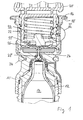
- Fig. 1
- eine CO2-Druckgasquelle im Längsschnitt; und
- Fig. 2
- die elastische Kunststoffkomponente einer Einzelheit II von
Fig. 1 . - Die CO2-Druckgasquelle ist als Einsatz ausgebildet, der durch das Spundloch eines Behälters hindurch in den Behälter paßt und das Spundloch dicht verschließt. Der Behälter wird durch das üblicherweise in der Mitte seines Oberbodens befindliche Spundloch unter Druck mit CO2-haltiger Flüssigkeit befüllt. Sodann wird das Spundloch mit dem Einsatz verschlossen.
- Zur Entnahme der Flüssigkeit kann ein integrierter Auslaufhahn dienen, der sich auf Unterbodenhöhe des Behälters an dessen Seitenwand befindet. Die Flüssigkeit läuft durch Innendruck und Schwerkraftwirkung aus, bis im Kopfraum des Behälters oberhalb des Flüssigkeitspegels darin ein Unterdruck erreicht ist. Diesen richtig einzustellen und geregelt aufrechtzuerhalten, wird die CO2-Druckgasquelle aktiviert. Die CO2-Druckgasquelle speist CO2 unter einem Druck in den Kopfraum des Behälters ein, der dem Partialdruck des in der Flüssigkeit gelösten CO2 entspricht oder diesen Partialdruck geringfügig übersteigt. Dadurch ist eine stetige Entleerung des Behälters gewährleistet. Es gelangt keine Luft in den Kopfraum des Behälters. Der CO2-Gehalt der Flüssigkeit bleibt gleich.
- Der Einsatz ist von länglich-schlanker Form und größtenteils radialsymmetrisch zu einer zentralen Achse aufgebaut. Er besteht überwiegend aus Kunststoff. Für die Herstellung bietet sich die Zweikomponenten-Kunststoffspritzgußtechnik an.
- Der in Einbaustellung befindliche, das Spundloch des Behälters verschließende Einsatz ragt mit einem Gehäuse 10 in den Behälter hinein.
- Das Gehäuse 10 hat an seinem inneren Ende eine Kammer 12 für die Paßsitz-Aufnahme einer CO2-Hochdruckpatrone 14. Der Kopf der Patrone 14, an dessen Stirnfläche sie angestochen werden kann, ist dem Spundloch zugewandt.
- Das Gehäuse 10 sitzt außen mit einem umlaufenden Kragen 16 auf dem Bördelrand des Spundlochs auf. An den Kragen 16 ist eine Dichtung 18 angeformt, mit der der Einsatz das Spundloch abdichtet.
- Über den Kragen 16 steht nach außen ein in das Gehäuse 10 eingelassener Drehknopf 20 vor, bei dessen Betätigung die CO2-Patrone 14 angestochen wird. Der Drehknopf 20 hat ein steiles Außengewinde 22, mit dem er in ein komplementäres Innengewinde des Gehäuses 10 eingeschraubt ist.
- Zum Anstechen der CO2-Patrone 14 dient eine Anstechnadel 24, die mit dem Ventilglied eines Druckregelventils baulich vereinigt ist. Das Ventilglied ist mit einer elastischen Membran 26 in Achsmitte des Gehäuses 10 aufgehängt. Die Spitze der Anstechnadel 24 ist von der Stirnfläche der CO2-Patrone 14 nur wenig beabstandet.
- Bei einer axialen Stellbewegung der Anstechnadel 24 auf die CO2-Patrone 14 hin hebt das Ventilglied von einem Ventilsitz 28 des Druckregelventils ab. Der Ventilsitz 28 ist aus dem elastischen Dichtmaterial an das Gehäuse 10 angeformt.
- Die Anstechnadel 24 wird von einem Schieber 30 beaufschlagt, der zwischen dem Drehknopf 20 und der Anstechnadel 24 liegt. Der Schieber 30 ist längsverschieblich in dem Gehäuse 10 geführt. Bei Betätigung schraubt sich der Drehknopf 20 gegen den Schieber 30 vor, der dabei axial verstellt wird.
- Zwischen Drehknopf 20 und Schieber 30 ist eine Schraubendruckfeder 32 eingespannt. Die Schraubendruckfeder 32 spannt den Schieber 30 gegen die Anstechnadel 24 vor.
- Die Membran 26 begrenzt einen Arbeitsraum stromab von dem Ventilsitz 28 des Druckregelventils. Der Arbeitsraum hat eine seitliche Auslaßöffnung, vor der ein elastischer Dichtring 34 liegt. Der Dichtring 34 hat die Funktion eines Rückschlagventils. Er verhindert, daß Flüssigkeit in den Einsatz gelangt.
- Zum Anstechen der CO2-Patrone 14 wird der Drehknopf 20 um ca. 90° gedreht. Der Schieber 30 wird durch den Schraubenvorschub des Drehknopfs 20 axial nach innen verstellt. Die Anstechnadel 24 wird unter elastischer Verformung der Membran 26 axial nach innen mitgenommen. Das Ventilglied hebt von dem Ventilsitz 28 ab. Nach dem Anstechen füllt sich ein sehr kleiner Ventilraum vor dem Kopf der CO2-Patrone 14 mit unter hohem Druck stehendem CO2.
- Nach vollendeter 90°-Drehung bzw. Überdrehung des Drehknopfs 20 springt der Schieber 30 gegen die Kraft der Schraubendruckfeder 32 axial nach außen zurück. Er wird dazu von der Anstechnadel 24 betätigt, die durch die elastische Rückverformung der Membran 26 axial zurückgestellt wird. Die Schraubendruckfeder 32 wird gespannt. Das Druckregelventil wird geschlossen und eine kleine Menge von unter hohem Druck stehendem CO2 in den Arbeitsraum eingelassen. Die CO2-Druckkräfte an der Membran 26 tragen zu dem anstechnadelbetätigten Rückspringen des Schiebers 30 bei.
- Das weitere Öffnen und Schließen des Druckregelventils wird durch ein Kräftegleichgewicht an der Membran 26 bestimmt, zu dem die elastischen Eigenschaften der Membran 26, die Federkonstante der Schraubendruckfeder 32 und der CO2-Druck in dem Arbeitsraum beitragen. Für den Druck des ausgegebenen CO2 ist die Federkonstante der Schraubendruckfeder 32 bestimmend.
- Gemeinhin wird der Benutzer die CO2-Druckgasquelle aktivieren, wenn der Innendruck in dem Behälter soweit abgefallen ist, daß der Strahl der durch den Auslaufhahn austretenden Flüssigkeit zu schwach wird. Die CO2-Druckgasquelle kann aber ohne weiteres auch schon vorher aktiviert werden, wenn der Innendruck in dem Behälter noch hoch ist, sehr wohl sogar bei dem erstmaligen Bedienungsangriff des Benutzers an dem Behälter überhaupt. Eine Eindosierung von CO2 in den Kopfraum des Behälters findet solange nicht statt, wie der hohe Innendruck auf dem Dichtring 34 vor der Auslaßöffnung lastet.
- Die CO2-Druckgasquelle ist mit einer Überdrucksicherung versehen, die wirksam wird, wenn das Druckregelventil versagt und CO2 unter unkontrolliert hohem Druck in den Kopfraum des Behälters gelangt.
- Als Überdrucksicherung ist an der Wand des Gehäuses 10 dicht vor dem Spundloch thermoplastisches Elastomer (TPE) angespritzt, dessen Partie geringster Materialdicke eine in die Wand versenkte Membran 36 bildet.
- Die Membran 36 steht mit dem Außenmantel des zum Anstechen der CO2-Patrone 14 noch nicht betätigten Drehknopfs 20 in bündiger Anlage. Sie ist dazu zwischen zwei benachbarten Gewindegängen des Außengewindes 22 an dem Drehknopf 20 plaziert.
- Die 90°-Drehung des Drehknopfs 20 zum Anstechen der CO2-Patrone 14 stellt der Membran 36 ein Fenster im Mantel des Drehknopfs 20 gegenüber. Bei unkontrolliert ansteigendem Innendruck kann sich die Membran 36 in dieses Fenster hinein elastisch ausdehnen, bis sie bei ca. 5,7 Bar an der Stelle geringster Materialdicke birst. Dadurch wird ein Strömungsweg vom Kopfraum des Behälters an den Mantel des Drehknopfs 20 eröffnet, der gegen den Kragen 16 nicht absolut dicht ist, so daß das CO2 aus dem Kopfraum des Behälters zur Atmosphäre hin abströmen kann.
-
- 10
- Gehäuse
- 12
- Kammer
- 14
- CO2-Hochdruckpatrone
- 16
- Kragen
- 18
- Dichtung
- 20
- Drehknopf
- 22
- Außengewinde
- 24
- Anstechnadel
- 26
- Membran
- 28
- Ventilsitz
- 30
- Schieber
- 32
- Schraubendruckfeder
- 34
- Dichtring
- 36
- Membran
Claims (8)
- Behälter, der mit Flüssigkeit befüllbar und druckdicht verschließbar und aus dem Flüssigkeit entnehmbar ist, mit einem Einsatz, der unter Abdichtung in einer Öffnung des Behälters festlegbar ist und eine CO2-Hochdruckpatrone (14), ein Druckregelventil zum Ausgeben von CO2 daraus und ein von außen zugängliches Stellglied aufweist, durch dessen Betätigung die CO2-Hochdruck-patrone (14) anstechbar ist, und mit einer Überdrucksicherung, die bei einem unerwünschten Druckanstieg in dem Behälter einen Strömungsweg von dessen Kopfraum durch den Einsatz zur Atmosphäre hin freigibt, dadurch gekennzeichnet, daß die Überdrucksicherung nach Überschreitung eines Innendrucks, bei dem der Behälter sichtlich bombiert, jedoch vor Erreichen eines Innendrucks, bei dem der Behälter platzt, birst.
- Behälter nach Anspruch 1, dadurch gekennzeichnet, daß der Strömungsweg über eine Undichtigkeit des Stellglieds führt.
- Behälter nach Anspruch 1 oder 2, dadurch gekennzeichnet, daß die Überdrucksicherung vor dem Anstechen der CO2-Hochdruckpatrone (14) unwirksam und durch das Anstechen der CO2-Hochdruckpatrone (14) aktivierbar ist.
- Behälter nach einem der Ansprüche 1 bis 3, dadurch gekennzeichnet, daß die Überdrucksicherung bei einem Innendruck von 4,0 bis 9,0 Bar, vorzugsweise 4,5 bis 7,0 Bar, weiter vorzugsweise 5,0 bis 6,0 Bar birst.
- Behälter nach einem der Ansprüche 1 bis 4, dadurch gekennzeichnet, daß die berstende Partie der Überdrucksicherung eine Membran (36) ist.
- Behälter nach Anspruch 5, dadurch gekennzeichnet, daß sich die Membran vor dem Anstechen der CO2-Hochdruckpatrone (14) an dem Stellglied abstützt und beim Anstechen der CO2-Hochdruckpatrone (14) von dem Stellglied freikommt.
- Behälter nach Anspruch 5 oder 6, dadurch gekennzeichnet, daß die Membran (36) in dem Einsatz versenkt zu liegen kommt.
- Behälter nach einem der Ansprüche 5 bis 7, dadurch gekennzeichnet, daß die Membran (36) aus elastischem Kunststoff besteht.
Priority Applications (9)
| Application Number | Priority Date | Filing Date | Title |
|---|---|---|---|
| EP07009281A EP1990309B1 (de) | 2007-05-09 | 2007-05-09 | Behälter mit CO2-Druckgasquelle und Überdruck-Berstsicherung |
| PCT/EP2008/003611 WO2008138513A1 (de) | 2007-05-09 | 2008-05-06 | Behälter mit co2-druckgasquelle und überdruck-berstsicherung |
| CA002679984A CA2679984A1 (en) | 2007-05-09 | 2008-05-06 | Container having co2 compressed gas source and overpressure burst safeguard |
| CN200880015437.5A CN101687624B (zh) | 2007-05-09 | 2008-05-06 | 带有co2压缩气体源和过压开裂保险装置的容器 |
| BRPI0810793-9A2A BRPI0810793A2 (pt) | 2007-05-09 | 2008-05-06 | Recipiente com fonte de gás co2 comprimido e proteção contra explosão por sobrepressão. |
| AU2008250673A AU2008250673A1 (en) | 2007-05-09 | 2008-05-06 | Container having CO2 compressed gas source and overpressure burst safeguard |
| US12/597,140 US20100140265A1 (en) | 2007-05-09 | 2008-05-06 | Container having co2 compressed gas source and overpressure burst safeguard |
| JP2010506843A JP2010526263A (ja) | 2007-05-09 | 2008-05-06 | Co2圧縮ガス源と超過圧力保護手段とを有する容器 |
| EA200971039A EA200971039A1 (ru) | 2007-05-09 | 2008-05-06 | Резервуар с источником сжатого углекислого газа и защитой от разрыва при избыточном давлении |
Applications Claiming Priority (1)
| Application Number | Priority Date | Filing Date | Title |
|---|---|---|---|
| EP07009281A EP1990309B1 (de) | 2007-05-09 | 2007-05-09 | Behälter mit CO2-Druckgasquelle und Überdruck-Berstsicherung |
Publications (2)
| Publication Number | Publication Date |
|---|---|
| EP1990309A1 true EP1990309A1 (de) | 2008-11-12 |
| EP1990309B1 EP1990309B1 (de) | 2012-09-26 |
Family
ID=38484452
Family Applications (1)
| Application Number | Title | Priority Date | Filing Date |
|---|---|---|---|
| EP07009281A Not-in-force EP1990309B1 (de) | 2007-05-09 | 2007-05-09 | Behälter mit CO2-Druckgasquelle und Überdruck-Berstsicherung |
Country Status (9)
| Country | Link |
|---|---|
| US (1) | US20100140265A1 (de) |
| EP (1) | EP1990309B1 (de) |
| JP (1) | JP2010526263A (de) |
| CN (1) | CN101687624B (de) |
| AU (1) | AU2008250673A1 (de) |
| BR (1) | BRPI0810793A2 (de) |
| CA (1) | CA2679984A1 (de) |
| EA (1) | EA200971039A1 (de) |
| WO (1) | WO2008138513A1 (de) |
Cited By (1)
| Publication number | Priority date | Publication date | Assignee | Title |
|---|---|---|---|---|
| WO2016180989A1 (en) * | 2015-05-14 | 2016-11-17 | Emmerald Polymers Limited | Pressure vessel |
Families Citing this family (6)
| Publication number | Priority date | Publication date | Assignee | Title |
|---|---|---|---|---|
| US9919910B2 (en) * | 2016-02-23 | 2018-03-20 | John Delano Gibson | Fluid pressurization and dispensing system |
| IL255921A (en) * | 2017-11-26 | 2018-01-31 | Wilder Haim | Adapter for a pressurized gas container |
| CN109515955B (zh) * | 2018-10-23 | 2020-05-05 | 塔罗斯科技股份有限公司 | 一种打酒器 |
| US11692671B2 (en) * | 2020-05-07 | 2023-07-04 | Numat Technologies, Inc. | Apparatus and method for dispensing gas from a storage vessel |
| US12491480B2 (en) * | 2021-10-08 | 2025-12-09 | Coravin, Inc. | Pressurized gas supply and gas cylinder |
| EP4506614B1 (de) * | 2023-08-08 | 2025-11-12 | FASS-FRISCH GmbH | Druckregelvorrichtung und verfahren zu dessen fertigung |
Citations (2)
| Publication number | Priority date | Publication date | Assignee | Title |
|---|---|---|---|---|
| EP1642861A1 (de) | 2004-09-29 | 2006-04-05 | Timm Oberhofer | Behälter mit CO2-Druckgasquelle |
| EP1688813A1 (de) | 2005-02-02 | 2006-08-09 | Impress GmbH & Co. oHG | Druckminder- und Regulierventil mit Anstechmechanismus einer im Faßverschluss montierbaren Gaspatrone |
Family Cites Families (6)
| Publication number | Priority date | Publication date | Assignee | Title |
|---|---|---|---|---|
| US2072816A (en) * | 1935-07-05 | 1937-03-02 | Walter Kidde Sales Company | Valve for aerating liquid vessels |
| JP4098862B2 (ja) | 1997-12-19 | 2008-06-11 | サッポロビール株式会社 | 炭酸飲料注出装置 |
| NL1019562C2 (nl) * | 2001-12-13 | 2003-06-17 | Heineken Tech Services | Klepsamenstel voor gebruik bij drankafgifte. |
| NL1023968C2 (nl) * | 2003-07-21 | 2005-01-24 | Heineken Tech Services | Drukregelaar voor houder voor koolzuurhoudende drank. |
| GB0411288D0 (en) * | 2004-05-20 | 2004-06-23 | Interbrew Sa | Alcohol beverage apparatus having a bursting disk |
| ES2321018T3 (es) * | 2004-06-25 | 2009-06-01 | Impress Group B.V. | Espita desechable para un recipiente de liquidos bajo presion. |
-
2007
- 2007-05-09 EP EP07009281A patent/EP1990309B1/de not_active Not-in-force
-
2008
- 2008-05-06 AU AU2008250673A patent/AU2008250673A1/en not_active Abandoned
- 2008-05-06 JP JP2010506843A patent/JP2010526263A/ja active Pending
- 2008-05-06 BR BRPI0810793-9A2A patent/BRPI0810793A2/pt not_active IP Right Cessation
- 2008-05-06 EA EA200971039A patent/EA200971039A1/ru unknown
- 2008-05-06 US US12/597,140 patent/US20100140265A1/en not_active Abandoned
- 2008-05-06 WO PCT/EP2008/003611 patent/WO2008138513A1/de not_active Ceased
- 2008-05-06 CN CN200880015437.5A patent/CN101687624B/zh not_active Expired - Fee Related
- 2008-05-06 CA CA002679984A patent/CA2679984A1/en not_active Abandoned
Patent Citations (2)
| Publication number | Priority date | Publication date | Assignee | Title |
|---|---|---|---|---|
| EP1642861A1 (de) | 2004-09-29 | 2006-04-05 | Timm Oberhofer | Behälter mit CO2-Druckgasquelle |
| EP1688813A1 (de) | 2005-02-02 | 2006-08-09 | Impress GmbH & Co. oHG | Druckminder- und Regulierventil mit Anstechmechanismus einer im Faßverschluss montierbaren Gaspatrone |
Cited By (1)
| Publication number | Priority date | Publication date | Assignee | Title |
|---|---|---|---|---|
| WO2016180989A1 (en) * | 2015-05-14 | 2016-11-17 | Emmerald Polymers Limited | Pressure vessel |
Also Published As
| Publication number | Publication date |
|---|---|
| CA2679984A1 (en) | 2008-11-20 |
| EA200971039A1 (ru) | 2010-04-30 |
| CN101687624A (zh) | 2010-03-31 |
| JP2010526263A (ja) | 2010-07-29 |
| WO2008138513A1 (de) | 2008-11-20 |
| EP1990309B1 (de) | 2012-09-26 |
| US20100140265A1 (en) | 2010-06-10 |
| BRPI0810793A2 (pt) | 2014-10-29 |
| AU2008250673A1 (en) | 2008-11-20 |
| CN101687624B (zh) | 2013-02-27 |
Similar Documents
| Publication | Publication Date | Title |
|---|---|---|
| EP1990309B1 (de) | Behälter mit CO2-Druckgasquelle und Überdruck-Berstsicherung | |
| EP1642861B1 (de) | Behälter mit CO2-Druckgasquelle | |
| EP1642862B1 (de) | Behälter mit CO2-Druckgasquelle | |
| EP1688814B1 (de) | Druckminder- und Regulierventil mit Anstechmechanismus einer im Fassverschluss montierbaren Gaspatrone | |
| DE69304658T2 (de) | Das Nachfüllen verhinderndes Ventil für nicht nachfüllbare Behälter | |
| DE19502929A1 (de) | Auslöseadapter für Druckgaspatrone | |
| EP3614036B1 (de) | Anschlussvorrichtung für einen gasdruckbehälter | |
| DE2362422A1 (de) | Selbsttaetig absperrende zapfpistole | |
| DE8526717U1 (de) | Strömungsregeleinrichtung | |
| DE202015100294U1 (de) | Trinkflaschenverschluss für mit kohlensäurehaltigen Getränken befüllbare Trinkflaschen | |
| EP3738920B1 (de) | Getränkebehälter und ein regelventil für einen getränkebehälter | |
| WO2006128653A1 (de) | Behälter mit co2-druckgasquelle | |
| EP2128043A2 (de) | Ventil für einen Druckgasbehälter | |
| EP4412943B1 (de) | Zapf- und regeleinrichtung sowie behältnis mit einer solchen zapf- und regeleinrichtung | |
| EP1648813A1 (de) | Schaumdrossel | |
| EP0054717A1 (de) | Vorrichtung zur Entnahme von Gas | |
| EP4412944B1 (de) | Zapf- und regeleinrichtung zum ausbringen einer flüssigkeit aus einem behältnis | |
| DE102022201891A1 (de) | Zapf- und Regeleinrichtung sowie Behältnis mit einer solchen Zapf- und Regeleinrichtung | |
| EP3105170B1 (de) | Zapfkopf für ein getränkefass | |
| DE102009024715A1 (de) | Steigrohr für ein Weinfaß | |
| DE3222041A1 (de) | Restdruckventil | |
| DE102007061536B4 (de) | Nachfüllbehälter für einen Tank | |
| DE4337802A1 (de) | Handpistole zur Druckgasbefüllung oder -belieferung von Kleingeräten aller Art, insbesondere zum Aufpumpen von Fahrzeugreifen | |
| AT254157B (de) | Kugelventil für Flüssiggasflaschen | |
| DE2521099B2 (de) | Druckversorgungsteil für aus druckdichten Behältern zu entnehmende Flüssigkeiten |
Legal Events
| Date | Code | Title | Description |
|---|---|---|---|
| PUAI | Public reference made under article 153(3) epc to a published international application that has entered the european phase |
Free format text: ORIGINAL CODE: 0009012 |
|
| AK | Designated contracting states |
Kind code of ref document: A1 Designated state(s): AT BE BG CH CY CZ DE DK EE ES FI FR GB GR HU IE IS IT LI LT LU LV MC MT NL PL PT RO SE SI SK TR |
|
| AX | Request for extension of the european patent |
Extension state: AL BA HR MK RS |
|
| 17P | Request for examination filed |
Effective date: 20090326 |
|
| AKX | Designation fees paid |
Designated state(s): AT BE BG CH CY CZ DE DK EE ES FI FR GB GR HU IE IS IT LI LT LU LV MC MT NL PL PT RO SE SI SK TR |
|
| GRAP | Despatch of communication of intention to grant a patent |
Free format text: ORIGINAL CODE: EPIDOSNIGR1 |
|
| GRAS | Grant fee paid |
Free format text: ORIGINAL CODE: EPIDOSNIGR3 |
|
| GRAA | (expected) grant |
Free format text: ORIGINAL CODE: 0009210 |
|
| AK | Designated contracting states |
Kind code of ref document: B1 Designated state(s): AT BE BG CH CY CZ DE DK EE ES FI FR GB GR HU IE IS IT LI LT LU LV MC MT NL PL PT RO SE SI SK TR |
|
| REG | Reference to a national code |
Ref country code: GB Ref legal event code: FG4D Free format text: NOT ENGLISH |
|
| REG | Reference to a national code |
Ref country code: CH Ref legal event code: EP |
|
| REG | Reference to a national code |
Ref country code: AT Ref legal event code: REF Ref document number: 576950 Country of ref document: AT Kind code of ref document: T Effective date: 20121015 |
|
| REG | Reference to a national code |
Ref country code: IE Ref legal event code: FG4D Free format text: LANGUAGE OF EP DOCUMENT: GERMAN |
|
| RAP2 | Party data changed (patent owner data changed or rights of a patent transferred) |
Owner name: HUBER PACKAGING GROUP GMBH |
|
| REG | Reference to a national code |
Ref country code: DE Ref legal event code: R096 Ref document number: 502007010585 Country of ref document: DE Effective date: 20121122 |
|
| REG | Reference to a national code |
Ref country code: DE Ref legal event code: R081 Ref document number: 502007010585 Country of ref document: DE Owner name: HUBER PACKAGING GROUP GMBH, DE Free format text: FORMER OWNER: KURT OBERHOFER,TIMM OBERHOFER, , DE Effective date: 20121107 Ref country code: DE Ref legal event code: R081 Ref document number: 502007010585 Country of ref document: DE Owner name: HUBER PACKAGING GROUP GMBH, DE Free format text: FORMER OWNERS: OBERHOFER, KURT, 69259 WILHELMSFELD, DE; OBERHOFER, TIMM, 69259 WILHELMSFELD, DE Effective date: 20121107 |
|
| PG25 | Lapsed in a contracting state [announced via postgrant information from national office to epo] |
Ref country code: FI Free format text: LAPSE BECAUSE OF FAILURE TO SUBMIT A TRANSLATION OF THE DESCRIPTION OR TO PAY THE FEE WITHIN THE PRESCRIBED TIME-LIMIT Effective date: 20120926 Ref country code: LT Free format text: LAPSE BECAUSE OF FAILURE TO SUBMIT A TRANSLATION OF THE DESCRIPTION OR TO PAY THE FEE WITHIN THE PRESCRIBED TIME-LIMIT Effective date: 20120926 |
|
| REG | Reference to a national code |
Ref country code: LT Ref legal event code: MG4D Effective date: 20120926 |
|
| REG | Reference to a national code |
Ref country code: NL Ref legal event code: VDEP Effective date: 20120926 |
|
| PG25 | Lapsed in a contracting state [announced via postgrant information from national office to epo] |
Ref country code: SI Free format text: LAPSE BECAUSE OF FAILURE TO SUBMIT A TRANSLATION OF THE DESCRIPTION OR TO PAY THE FEE WITHIN THE PRESCRIBED TIME-LIMIT Effective date: 20120926 Ref country code: GR Free format text: LAPSE BECAUSE OF FAILURE TO SUBMIT A TRANSLATION OF THE DESCRIPTION OR TO PAY THE FEE WITHIN THE PRESCRIBED TIME-LIMIT Effective date: 20121227 Ref country code: LV Free format text: LAPSE BECAUSE OF FAILURE TO SUBMIT A TRANSLATION OF THE DESCRIPTION OR TO PAY THE FEE WITHIN THE PRESCRIBED TIME-LIMIT Effective date: 20120926 Ref country code: SE Free format text: LAPSE BECAUSE OF FAILURE TO SUBMIT A TRANSLATION OF THE DESCRIPTION OR TO PAY THE FEE WITHIN THE PRESCRIBED TIME-LIMIT Effective date: 20120926 |
|
| PG25 | Lapsed in a contracting state [announced via postgrant information from national office to epo] |
Ref country code: RO Free format text: LAPSE BECAUSE OF FAILURE TO SUBMIT A TRANSLATION OF THE DESCRIPTION OR TO PAY THE FEE WITHIN THE PRESCRIBED TIME-LIMIT Effective date: 20120926 Ref country code: IS Free format text: LAPSE BECAUSE OF FAILURE TO SUBMIT A TRANSLATION OF THE DESCRIPTION OR TO PAY THE FEE WITHIN THE PRESCRIBED TIME-LIMIT Effective date: 20130126 Ref country code: ES Free format text: LAPSE BECAUSE OF FAILURE TO SUBMIT A TRANSLATION OF THE DESCRIPTION OR TO PAY THE FEE WITHIN THE PRESCRIBED TIME-LIMIT Effective date: 20130106 Ref country code: CZ Free format text: LAPSE BECAUSE OF FAILURE TO SUBMIT A TRANSLATION OF THE DESCRIPTION OR TO PAY THE FEE WITHIN THE PRESCRIBED TIME-LIMIT Effective date: 20120926 Ref country code: NL Free format text: LAPSE BECAUSE OF FAILURE TO SUBMIT A TRANSLATION OF THE DESCRIPTION OR TO PAY THE FEE WITHIN THE PRESCRIBED TIME-LIMIT Effective date: 20120926 Ref country code: EE Free format text: LAPSE BECAUSE OF FAILURE TO SUBMIT A TRANSLATION OF THE DESCRIPTION OR TO PAY THE FEE WITHIN THE PRESCRIBED TIME-LIMIT Effective date: 20120926 |
|
| PG25 | Lapsed in a contracting state [announced via postgrant information from national office to epo] |
Ref country code: PT Free format text: LAPSE BECAUSE OF FAILURE TO SUBMIT A TRANSLATION OF THE DESCRIPTION OR TO PAY THE FEE WITHIN THE PRESCRIBED TIME-LIMIT Effective date: 20130128 Ref country code: SK Free format text: LAPSE BECAUSE OF FAILURE TO SUBMIT A TRANSLATION OF THE DESCRIPTION OR TO PAY THE FEE WITHIN THE PRESCRIBED TIME-LIMIT Effective date: 20120926 Ref country code: PL Free format text: LAPSE BECAUSE OF FAILURE TO SUBMIT A TRANSLATION OF THE DESCRIPTION OR TO PAY THE FEE WITHIN THE PRESCRIBED TIME-LIMIT Effective date: 20120926 Ref country code: CY Free format text: LAPSE BECAUSE OF FAILURE TO SUBMIT A TRANSLATION OF THE DESCRIPTION OR TO PAY THE FEE WITHIN THE PRESCRIBED TIME-LIMIT Effective date: 20120926 |
|
| PG25 | Lapsed in a contracting state [announced via postgrant information from national office to epo] |
Ref country code: BG Free format text: LAPSE BECAUSE OF FAILURE TO SUBMIT A TRANSLATION OF THE DESCRIPTION OR TO PAY THE FEE WITHIN THE PRESCRIBED TIME-LIMIT Effective date: 20121226 Ref country code: DK Free format text: LAPSE BECAUSE OF FAILURE TO SUBMIT A TRANSLATION OF THE DESCRIPTION OR TO PAY THE FEE WITHIN THE PRESCRIBED TIME-LIMIT Effective date: 20120926 |
|
| PLBE | No opposition filed within time limit |
Free format text: ORIGINAL CODE: 0009261 |
|
| STAA | Information on the status of an ep patent application or granted ep patent |
Free format text: STATUS: NO OPPOSITION FILED WITHIN TIME LIMIT |
|
| PG25 | Lapsed in a contracting state [announced via postgrant information from national office to epo] |
Ref country code: IT Free format text: LAPSE BECAUSE OF FAILURE TO SUBMIT A TRANSLATION OF THE DESCRIPTION OR TO PAY THE FEE WITHIN THE PRESCRIBED TIME-LIMIT Effective date: 20120926 |
|
| 26N | No opposition filed |
Effective date: 20130627 |
|
| REG | Reference to a national code |
Ref country code: DE Ref legal event code: R097 Ref document number: 502007010585 Country of ref document: DE Effective date: 20130627 |
|
| BERE | Be: lapsed |
Owner name: OBERHOFER, KURT Effective date: 20130531 Owner name: OBERHOFER, TIMM Effective date: 20130531 |
|
| PG25 | Lapsed in a contracting state [announced via postgrant information from national office to epo] |
Ref country code: MC Free format text: LAPSE BECAUSE OF FAILURE TO SUBMIT A TRANSLATION OF THE DESCRIPTION OR TO PAY THE FEE WITHIN THE PRESCRIBED TIME-LIMIT Effective date: 20120926 |
|
| REG | Reference to a national code |
Ref country code: CH Ref legal event code: PL |
|
| GBPC | Gb: european patent ceased through non-payment of renewal fee |
Effective date: 20130509 |
|
| PG25 | Lapsed in a contracting state [announced via postgrant information from national office to epo] |
Ref country code: CH Free format text: LAPSE BECAUSE OF NON-PAYMENT OF DUE FEES Effective date: 20130531 Ref country code: LI Free format text: LAPSE BECAUSE OF NON-PAYMENT OF DUE FEES Effective date: 20130531 |
|
| REG | Reference to a national code |
Ref country code: IE Ref legal event code: MM4A |
|
| PG25 | Lapsed in a contracting state [announced via postgrant information from national office to epo] |
Ref country code: BE Free format text: LAPSE BECAUSE OF NON-PAYMENT OF DUE FEES Effective date: 20130531 |
|
| PG25 | Lapsed in a contracting state [announced via postgrant information from national office to epo] |
Ref country code: GB Free format text: LAPSE BECAUSE OF NON-PAYMENT OF DUE FEES Effective date: 20130509 Ref country code: IE Free format text: LAPSE BECAUSE OF NON-PAYMENT OF DUE FEES Effective date: 20130509 |
|
| REG | Reference to a national code |
Ref country code: AT Ref legal event code: MM01 Ref document number: 576950 Country of ref document: AT Kind code of ref document: T Effective date: 20130509 |
|
| PG25 | Lapsed in a contracting state [announced via postgrant information from national office to epo] |
Ref country code: AT Free format text: LAPSE BECAUSE OF NON-PAYMENT OF DUE FEES Effective date: 20130509 |
|
| PGFP | Annual fee paid to national office [announced via postgrant information from national office to epo] |
Ref country code: DE Payment date: 20140628 Year of fee payment: 8 Ref country code: FR Payment date: 20140527 Year of fee payment: 8 |
|
| PG25 | Lapsed in a contracting state [announced via postgrant information from national office to epo] |
Ref country code: MT Free format text: LAPSE BECAUSE OF FAILURE TO SUBMIT A TRANSLATION OF THE DESCRIPTION OR TO PAY THE FEE WITHIN THE PRESCRIBED TIME-LIMIT Effective date: 20120926 |
|
| PG25 | Lapsed in a contracting state [announced via postgrant information from national office to epo] |
Ref country code: TR Free format text: LAPSE BECAUSE OF FAILURE TO SUBMIT A TRANSLATION OF THE DESCRIPTION OR TO PAY THE FEE WITHIN THE PRESCRIBED TIME-LIMIT Effective date: 20120926 |
|
| PG25 | Lapsed in a contracting state [announced via postgrant information from national office to epo] |
Ref country code: HU Free format text: LAPSE BECAUSE OF FAILURE TO SUBMIT A TRANSLATION OF THE DESCRIPTION OR TO PAY THE FEE WITHIN THE PRESCRIBED TIME-LIMIT; INVALID AB INITIO Effective date: 20070509 Ref country code: LU Free format text: LAPSE BECAUSE OF NON-PAYMENT OF DUE FEES Effective date: 20130509 |
|
| REG | Reference to a national code |
Ref country code: DE Ref legal event code: R119 Ref document number: 502007010585 Country of ref document: DE |
|
| REG | Reference to a national code |
Ref country code: FR Ref legal event code: ST Effective date: 20160129 |
|
| PG25 | Lapsed in a contracting state [announced via postgrant information from national office to epo] |
Ref country code: DE Free format text: LAPSE BECAUSE OF NON-PAYMENT OF DUE FEES Effective date: 20151201 |
|
| PG25 | Lapsed in a contracting state [announced via postgrant information from national office to epo] |
Ref country code: FR Free format text: LAPSE BECAUSE OF NON-PAYMENT OF DUE FEES Effective date: 20150601 |