EP1990228A1 - Kraftstofftank - Google Patents
Kraftstofftank Download PDFInfo
- Publication number
- EP1990228A1 EP1990228A1 EP08450065A EP08450065A EP1990228A1 EP 1990228 A1 EP1990228 A1 EP 1990228A1 EP 08450065 A EP08450065 A EP 08450065A EP 08450065 A EP08450065 A EP 08450065A EP 1990228 A1 EP1990228 A1 EP 1990228A1
- Authority
- EP
- European Patent Office
- Prior art keywords
- fuel tank
- recess
- tread
- outer side
- plates
- Prior art date
- Legal status (The legal status is an assumption and is not a legal conclusion. Google has not performed a legal analysis and makes no representation as to the accuracy of the status listed.)
- Granted
Links
- 239000002828 fuel tank Substances 0.000 title claims abstract description 35
- 238000005253 cladding Methods 0.000 claims description 2
- 238000009434 installation Methods 0.000 claims description 2
- 238000004049 embossing Methods 0.000 description 2
- 230000009194 climbing Effects 0.000 description 1
- 230000006735 deficit Effects 0.000 description 1
- 230000010354 integration Effects 0.000 description 1
- 238000004519 manufacturing process Methods 0.000 description 1
- 230000004048 modification Effects 0.000 description 1
- 238000012986 modification Methods 0.000 description 1
- 230000001360 synchronised effect Effects 0.000 description 1
Images

Classifications
-
- B—PERFORMING OPERATIONS; TRANSPORTING
- B60—VEHICLES IN GENERAL
- B60K—ARRANGEMENT OR MOUNTING OF PROPULSION UNITS OR OF TRANSMISSIONS IN VEHICLES; ARRANGEMENT OR MOUNTING OF PLURAL DIVERSE PRIME-MOVERS IN VEHICLES; AUXILIARY DRIVES FOR VEHICLES; INSTRUMENTATION OR DASHBOARDS FOR VEHICLES; ARRANGEMENTS IN CONNECTION WITH COOLING, AIR INTAKE, GAS EXHAUST OR FUEL SUPPLY OF PROPULSION UNITS IN VEHICLES
- B60K15/00—Arrangement in connection with fuel supply of combustion engines or other fuel consuming energy converters, e.g. fuel cells; Mounting or construction of fuel tanks
- B60K15/03—Fuel tanks
-
- B—PERFORMING OPERATIONS; TRANSPORTING
- B60—VEHICLES IN GENERAL
- B60R—VEHICLES, VEHICLE FITTINGS, OR VEHICLE PARTS, NOT OTHERWISE PROVIDED FOR
- B60R3/00—Arrangements of steps or ladders facilitating access to or on the vehicle, e.g. running-boards
- B60R3/02—Retractable steps or ladders, e.g. movable under shock
-
- B—PERFORMING OPERATIONS; TRANSPORTING
- B60—VEHICLES IN GENERAL
- B60Y—INDEXING SCHEME RELATING TO ASPECTS CROSS-CUTTING VEHICLE TECHNOLOGY
- B60Y2200/00—Type of vehicle
- B60Y2200/10—Road Vehicles
- B60Y2200/14—Trucks; Load vehicles, Busses
Definitions
- the present invention relates to a fuel tank for outdoor installation on a vehicle, with at least one hinged tread plate on the outside of the fuel tank facing away from the vehicle.
- tread plates are either welded rigidly to the outside of the fuel tank, or a pot-like insert is used in the wall of the fuel tank, which itself forms the tread or rigid treads, or there are mounted in a separate tank from the attachment folding stages (see, eg DE 10 2004 005 153 A1 ).
- the former and latter variants have the disadvantage that they are bulky and increase the outer dimensions of the vehicle and thus its air resistance, and second variant has the disadvantage that it reduces the exploitable volume of the fuel tank sensitive.
- the invention has the object to provide a fuel tank with folding tread plate, which overcomes the disadvantages mentioned.
- This object is achieved according to the invention in that the at least one tread plate is mounted foldable in a recess of the outside of the fuel tank, wherein the tread plate (s) in the folded state substantially flush with the outside or any cladding or complete it.
- the recess is preferably formed by embossing or deep drawing of the wall of the fuel tank.
- the recess is preferably formed by a pot-like insert, which is sealed in the wall of the fuel tank.
- a cup-like insert is modular and can be combined with different fuel tanks.
- the recess supports two fold-out tread plates in order to achieve optimum tread height and comfort.
- the recess has such a depth that it is able to just absorb the thickness of the tread plates in the folded state. As a result, the impairment of the internal volume of the fuel tank is minimized.
- a particularly specialized characterizationsunan perennialer and stable folding mechanism for the tread plates is characterized in that the tread plates slide by means of laterally projecting bearing pin in slide guides of the recess and are held in the unfolded state by hinged to the recess folding struts.
- Fig. 1 shows a fuel tank 1 of approximately rounded parallelepipedian shape.
- a recess 3 is incorporated, for example by appropriate embossing or deep drawing of the wall of the fuel tank.
- the recess 3 is formed by a separate, pot-like insert which is sealed in the wall of the fuel tank, see Fig. 2 ,
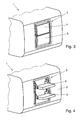
- the tread plates 4, 5 close substantially flush with the outer side 2 of the fuel tank 1 (see Fig. 3 ) or with any applied to the outside panel (not shown) from; in the unfolded state, they project approximately horizontally in order to be used as steps for climbing the vehicle ( Fig. 4 ).
- the recess 3 has a depth such that it the thickness of the tread plates 4, 5 in the folded state ( Fig. 3 ) just absorbs to affect the inner volume of the fuel tank 1 as little as possible.
- the folding mechanism of the tread plates 4, 5 is in Fig. 2 shown in detail.
- Each tread plate 4, 5 slides by means of bilaterally projecting bearing pin 6 in side slide guides 7 serving here as a recess 3 insert.
- the tread plates 4, 5 are held by hinged on the insert hinged struts 8.
- hinged connecting rods 9 couple the tread plates to a synchronous movement.
Landscapes
- Engineering & Computer Science (AREA)
- Mechanical Engineering (AREA)
- Life Sciences & Earth Sciences (AREA)
- Sustainable Development (AREA)
- Sustainable Energy (AREA)
- Chemical & Material Sciences (AREA)
- Combustion & Propulsion (AREA)
- Transportation (AREA)
- Cooling, Air Intake And Gas Exhaust, And Fuel Tank Arrangements In Propulsion Units (AREA)
Abstract
Description
- Die vorliegende Erfindung betrifft einen Kraftstofftank zur Außenmontage an einem Fahrzeug, mit zumindest einer klappbaren Trittplatte an der dem Fahrzeug abgewandten Außenseite des Kraftstofftanks.
- Derzeit werden solche Trittplatten entweder starr an der Außenseite des Kraftstofftanks angeschweißt, oder es wird ein topfartiger Einsatz in die Wandung des Kraftstofftanks eingesetzt, welcher selbst die Trittstufe bildet oder starre Trittstufen enthält, oder es werden in einem vom Tank gesonderten Vorsatzgehäuse Klappstufen angebracht (siehe z.B.
DE 10 2004 005 153 A1 ). Erstere und letztere Varianten haben den Nachteil, daß sie sperrig sind und die Außenabmessungen des Fahrzeugs und damit seinen Luftwiderstand erhöhen, und zweitere Variante hat den Nachteil, daß sie das ausnutzbare Volumen des Kraftstofftanks empfindlich reduziert. - Die Erfindung setzt sich zum Ziel, einen Kraftstofftank mit klappbarer Trittplatte zu schaffen, welcher die genannten Nachteile überwindet. Dieses Ziel wird gemäß der Erfindung dadurch erreicht, daß die zumindest eine Trittplatte in einer Vertiefung der Außenseite des Kraftstofftanks herausklappbar gelagert ist, wobei die Trittplatte(n) im eingeklappten Zustand im wesentlichen bündig mit der Außenseite oder einer allfälligen Verkleidung derselben abschließt bzw. abschließen.
- Dies ergibt eine überaus kompakte Integration einer Trittplattenfunktion in einen Kraftstofftank, welche weder die Außenabmessungen und den Luftwiderstand des Fahrzeuges noch das ausnutzbare Volumen des Tankes nennenswert beeinträchtigt.
- Eine besonders einfache Fertigung ergibt sich, wenn die Vertiefung bevorzugt durch Prägen oder Tiefziehen der Wandung des Kraftstofftanks gebildet ist. Alternativ wird die Vertiefung bevorzugt durch einen topfartigen Einsatz gebildet, welcher in die Wandung des Kraftstofftanks dicht eingelassen ist. Ein solcher topfartiger Einsatz ist modular fertigbar und kann mit unterschiedlichen Kraftstofftanks kombiniert werden.
- Gemäß einer bevorzugten Ausführungsform lagert die Vertiefung zwei herausklappbare Trittplatten, um optimale Tritthöhe und -bequemlichkeit zu erreichen.
- Bevorzugt hat die Vertiefung eine solche Tiefe, daß sie die Dicke der Trittplatten im eingeklappten Zustand gerade aufzunehmen vermag. Dadurch wird die Beeinträchtigung des Innenvolumens des Kraftstofftanks möglichst gering gehalten.
- Ein besonders störungsunanfälliger und stabiler Klappmechanismus für die Trittplatten zeichnet sich dadurch aus, daß die Trittplatten mittels seitlich abstehender Lagerzapfen in Kulissenführungen der Vertiefung gleiten und im ausgeklappten Zustand durch an der Vertiefung angelenkte Klappstreben gehalten sind.
- Die Erfindung wird nachstehend anhand eines in den beigeschlossenen Zeichnungen dargestellten Ausführungsbeispieles näher erläutert. In den Zeichnungen zeigt:
-
Fig. 1 den Kraftstofftank der Erfindung in einer Perspektivansicht; -
Fig. 2 einen mittigen Vertikalschnitt durch den Einsatz mit den Trittplatten des Kraftstofftankes vonFig. 1 ; und
dieFig. 3 und 4 die vollständig ein- bzw. ausgeklappte Stellung der Trittplatten. -
Fig. 1 zeigt einen Kraftstofftank 1 von etwa abgerundetparallelepipedischer Form. In die dem Fahrzeug (nicht gezeigt) abgewandte Außenseite 2 des Kraftstofftanks 1 ist eine Vertiefung 3 eingearbeitet, beispielsweise durch entsprechendes Prägen oder Tiefziehen der Wandung des Kraftstofftanks 1. - In dem gezeigten Beispiel wird die Vertiefung 3 durch einen gesonderten, topfartigen Einsatz gebildet, der in die Wandung des Kraftstofftanks dicht eingelassen ist, siehe
Fig. 2 . - Die Vertiefung 3, hier der Einsatz, lagert zwei herausklappbare Trittplatten 4, 5. Es versteht sich, daß anstelle von zwei auch nur eine oder mehr als zwei Trittplatten vorhanden sein können. Im eingeklappten Zustand schließen die Trittplatten 4, 5 im wesentlichen bündig mit der Außenseite 2 des Kraftstofftanks 1 (siehe
Fig. 3 ) oder mit einer allfälligen auf die Außenseite aufgebrachten Verkleidung (nicht dargestellt) ab; im herausgeklappten Zustand kragen sie etwa waagrecht aus, um als Trittstufen zum Besteigen des Fahrzeuges verwendet werden zu können (Fig. 4 ). - Die Vertiefung 3 hat eine solche Tiefe, daß sie die Dicke der Trittplatten 4, 5 im eingeklappten Zustand (
Fig. 3 ) gerade aufnimmt, um das Innenvolumen des Kraftstofftanks 1 möglichst wenig zu beeinträchtigen. - Der Klappmechanismus der Trittplatten 4, 5 ist in
Fig. 2 im Detail gezeigt. Jede Trittplatte 4, 5 gleitet mittels beidseitig abstehender Lagerzapfen 6 in seitlichen Kulissenführungen 7 des hier als Vertiefung 3 dienenden Einsatzes. Im ausgeklappten Zustand werden die Trittplatten 4, 5 durch am Einsatz angelenkte Klappstreben 8 gehalten. An den Lagerzapfen 6 der beiden Trittplatten 4, 5 angelenkte Verbindungsstangen 9 kuppeln die Trittplatten zu einer gleichläufigen Bewegung. - Die Erfindung ist nicht auf die dargestellten Ausführungsbeispiele beschränkt, sondern umfaßt alle Varianten und Modifikationen, die in den Rahmen der angeschlossenen Ansprüche fallen. So kann beispielsweise anstelle des gezeigten bevorzugten Klappmechanismus auch jede andere in der Technik bekannte Art von Klappmechanismus für die Trittplatten vorgesehen werden.
Claims (6)
- Kraftstofftank (1) zur Außenmontage an einem Fahrzeug, mit zumindest einer klappbaren Trittplatte (4, 5) an der dem Fahrzeug abgewandten Außenseite (2) des Kraftstofftanks, dadurch gekennzeichnet, daß die zumindest eine Trittplatte (4, 5) in einer Vertiefung (3) der Außenseite (2) des Kraftstofftanks (1) herausklappbar gelagert ist, wobei die Trittplatte(n) (4, 5) im eingeklappten Zustand im wesentlichen bündig mit der Außenseite (2) oder einer allfälligen Verkleidung derselben abschließt bzw. abschließen.
- Kraftstofftank nach Anspruch 1, dadurch gekennzeichnet, daß die Vertiefung (3) durch Prägen oder Tiefziehen der Wandung des Kraftstofftanks (1) gebildet ist.
- Kraftstofftank nach Anspruch 1, dadurch gekennzeichnet, daß die Vertiefung (3) durch einen topfartigen Einsatz gebildet ist, welcher in die Wandung des Kraftstofftanks (1) dicht eingelassen ist.
- Kraftstofftank nach einem der Ansprüche 1 bis 3, dadurch gekennzeichnet, daß die Vertiefung (3) zwei herausklappbare Trittplatten (4, 5) lagert.
- Kraftstofftank nach einem der Ansprüche 1 bis 4, dadurch gekennzeichnet, daß die Vertiefung (3) eine solche Tiefe hat, daß sie die Dicke der Trittplatten (4, 5) im eingeklappten Zustand gerade aufzunehmen vermag.
- Kraftstofftank nach einem der Ansprüche 1 bis 5, dadurch gekennzeichnet, daß die Trittplatten (4, 5) mittels seitlich abstehender Lagerzapfen (6) in Kulissenführungen (7) der Vertiefung (3) gleiten und im ausgeklappten Zustand durch an der Vertiefung (3) angelenkte Klappstreben (8) gehalten sind.
Applications Claiming Priority (1)
| Application Number | Priority Date | Filing Date | Title |
|---|---|---|---|
| AT0029207U AT9909U1 (de) | 2007-05-10 | 2007-05-10 | Kraftstofftank |
Publications (2)
| Publication Number | Publication Date |
|---|---|
| EP1990228A1 true EP1990228A1 (de) | 2008-11-12 |
| EP1990228B1 EP1990228B1 (de) | 2010-12-01 |
Family
ID=39154348
Family Applications (1)
| Application Number | Title | Priority Date | Filing Date |
|---|---|---|---|
| EP08450065A Not-in-force EP1990228B1 (de) | 2007-05-10 | 2008-04-30 | Kraftstofftank |
Country Status (3)
| Country | Link |
|---|---|
| EP (1) | EP1990228B1 (de) |
| AT (2) | AT9909U1 (de) |
| DE (1) | DE502008001917D1 (de) |
Cited By (4)
| Publication number | Priority date | Publication date | Assignee | Title |
|---|---|---|---|---|
| CN102729613A (zh) * | 2012-07-02 | 2012-10-17 | 天津长荣印刷设备股份有限公司 | 一种两用踏板装置及其工作方法 |
| CN108583272A (zh) * | 2018-04-28 | 2018-09-28 | 安徽江淮汽车集团股份有限公司 | 一种油箱与登车装置的集成系统 |
| CN113386557A (zh) * | 2021-08-02 | 2021-09-14 | 一汽解放汽车有限公司 | 一种燃油箱总成装置及车辆 |
| US20230043466A1 (en) * | 2021-08-04 | 2023-02-09 | Cnh Industrial America Llc | Step with integrated water tank for agricultural vehicle |
Citations (4)
| Publication number | Priority date | Publication date | Assignee | Title |
|---|---|---|---|---|
| US3343703A (en) * | 1965-01-18 | 1967-09-26 | Gerald J Snyder | Tank construction |
| DE10033386A1 (de) | 2000-07-08 | 2002-01-31 | Man Nutzfahrzeuge Ag | Aufstieg zum Begehen eines Nutzfahrzeugs |
| DE20306793U1 (de) * | 2003-04-30 | 2003-08-14 | Gebr. Dingerkus GmbH & Co. KG, 57439 Attendorn | Geschlossener Behälter für Flüssigkeiten oder Gase |
| DE102004005153A1 (de) | 2004-02-03 | 2005-08-18 | Daimlerchrysler Ag | Anbausystem für Nutzfahrzeuge |
-
2007
- 2007-05-10 AT AT0029207U patent/AT9909U1/de not_active IP Right Cessation
-
2008
- 2008-04-30 AT AT08450065T patent/ATE490113T1/de active
- 2008-04-30 EP EP08450065A patent/EP1990228B1/de not_active Not-in-force
- 2008-04-30 DE DE502008001917T patent/DE502008001917D1/de active Active
Patent Citations (4)
| Publication number | Priority date | Publication date | Assignee | Title |
|---|---|---|---|---|
| US3343703A (en) * | 1965-01-18 | 1967-09-26 | Gerald J Snyder | Tank construction |
| DE10033386A1 (de) | 2000-07-08 | 2002-01-31 | Man Nutzfahrzeuge Ag | Aufstieg zum Begehen eines Nutzfahrzeugs |
| DE20306793U1 (de) * | 2003-04-30 | 2003-08-14 | Gebr. Dingerkus GmbH & Co. KG, 57439 Attendorn | Geschlossener Behälter für Flüssigkeiten oder Gase |
| DE102004005153A1 (de) | 2004-02-03 | 2005-08-18 | Daimlerchrysler Ag | Anbausystem für Nutzfahrzeuge |
Cited By (5)
| Publication number | Priority date | Publication date | Assignee | Title |
|---|---|---|---|---|
| CN102729613A (zh) * | 2012-07-02 | 2012-10-17 | 天津长荣印刷设备股份有限公司 | 一种两用踏板装置及其工作方法 |
| CN108583272A (zh) * | 2018-04-28 | 2018-09-28 | 安徽江淮汽车集团股份有限公司 | 一种油箱与登车装置的集成系统 |
| CN113386557A (zh) * | 2021-08-02 | 2021-09-14 | 一汽解放汽车有限公司 | 一种燃油箱总成装置及车辆 |
| US20230043466A1 (en) * | 2021-08-04 | 2023-02-09 | Cnh Industrial America Llc | Step with integrated water tank for agricultural vehicle |
| US11932203B2 (en) * | 2021-08-04 | 2024-03-19 | Cnh Industrial America Llc | Step with integrated water tank for agricultural vehicle |
Also Published As
| Publication number | Publication date |
|---|---|
| AT9909U1 (de) | 2008-05-15 |
| DE502008001917D1 (de) | 2011-01-13 |
| ATE490113T1 (de) | 2010-12-15 |
| EP1990228B1 (de) | 2010-12-01 |
Similar Documents
| Publication | Publication Date | Title |
|---|---|---|
| EP1439090B1 (de) | Rücksitzlehne für einen Fahrzeugrücksitz | |
| DE102010054038B4 (de) | Gemeinsame Basis für manuell einziehbare und elektrisch einziehbare Fahrzeugtürspiegel, manuell einziehbarer Fahrzeugtürspiegel, elektrisch einziehbarer Fahrzeugtürspiegel und Verfahren zum selektiven Herstellen eines manuell einziehbaren/elektrisch einziehbaren Fahrzeugtürspiegels | |
| DE102010061308A1 (de) | Höhenverstellbare Kopfstütze | |
| DE102013205497B4 (de) | Sitzschienen-Abschlusskappe und Bewegungsanschlag-Sitzpositions-Sensor | |
| EP1792786A3 (de) | Crashbox | |
| DE202014007242U1 (de) | Ausstattungselement für ein Gehäusemittelteil einer Armbanduhr | |
| DE102011082651A1 (de) | Spiegelfuß für einen Außenspiegel eines Kraftfahrzeugs sowie Herstellungsverfahren für einen Spiegelfuß | |
| EP1990228A1 (de) | Kraftstofftank | |
| EP0826534A2 (de) | Sonnenblende für Fahrzeuge | |
| CH697701B1 (de) | Verfahren zur Herstellung bedruckter und geprägter Deckel für Cremedosen sowie solche Deckel. | |
| DE112012000281T5 (de) | Zahnteilherstellungsverfahren, Zahnteilherstellungsvorrichtung und Zahnteil | |
| EP1650114B1 (de) | Aerodynamische Verkleidung für ein Kraftfahrzeug | |
| EP3179060A1 (de) | Zylinderkopfhaube | |
| DE102011051719A1 (de) | Mittelkonsole | |
| DE102012106838A1 (de) | Fahrzeugkarosserie und Formverfahren davon | |
| DE703137C (de) | Aus je einem aeusseren und inneren Wandungsteil zusammengesetzte Kraftfahrzeugtuer | |
| DE102010052477B4 (de) | Lehnenbezug für eine Rückenlehne eines Fahrzeugsitzes | |
| DE102008060591B3 (de) | Zierelement für ein Automobil und Fahrzeugteil mit einem Zierelement | |
| EP2228260B1 (de) | Einfacher, leichter Rückblickspiegel | |
| DE202007002166U1 (de) | Abfallsammler | |
| EP2091770B1 (de) | Austattungsteil, insbesondere für ein kraftfahrzeug, mit einem ersten teilbereich und einem einstückig mittels eines verbindungungsbereichs angebundenen zweiten teilbereich | |
| DE2807516A1 (de) | Verfahren zur spanlosen kaltformung eines innenverzahnten metall-werkstueckes, insbesondere eines sitzbeschlagteiles eines kraftfahrzeugsitzes und nach dem verfahren hergestellter gegenstand | |
| EP2815679B1 (de) | Schrankmöbel | |
| DE112007001634T5 (de) | Scharnier zur Befestigung von Innenraumteilen von Kraftfahrzeugen | |
| DE615287C (de) | Verfahren zur Herstellung von Reissverschlussschiebern |
Legal Events
| Date | Code | Title | Description |
|---|---|---|---|
| PUAI | Public reference made under article 153(3) epc to a published international application that has entered the european phase |
Free format text: ORIGINAL CODE: 0009012 |
|
| AK | Designated contracting states |
Kind code of ref document: A1 Designated state(s): AT BE BG CH CY CZ DE DK EE ES FI FR GB GR HR HU IE IS IT LI LT LU LV MC MT NL NO PL PT RO SE SI SK TR |
|
| AX | Request for extension of the european patent |
Extension state: AL BA MK RS |
|
| 17P | Request for examination filed |
Effective date: 20090508 |
|
| AKX | Designation fees paid |
Designated state(s): AT BE BG CH CY CZ DE DK EE ES FI FR GB GR HR HU IE IS IT LI LT LU LV MC MT NL NO PL PT RO SE SI SK TR |
|
| GRAP | Despatch of communication of intention to grant a patent |
Free format text: ORIGINAL CODE: EPIDOSNIGR1 |
|
| GRAS | Grant fee paid |
Free format text: ORIGINAL CODE: EPIDOSNIGR3 |
|
| GRAA | (expected) grant |
Free format text: ORIGINAL CODE: 0009210 |
|
| AK | Designated contracting states |
Kind code of ref document: B1 Designated state(s): AT BE BG CH CY CZ DE DK EE ES FI FR GB GR HR HU IE IS IT LI LT LU LV MC MT NL NO PL PT RO SE SI SK TR |
|
| REG | Reference to a national code |
Ref country code: GB Ref legal event code: FG4D Free format text: NOT ENGLISH |
|
| REG | Reference to a national code |
Ref country code: CH Ref legal event code: EP |
|
| REG | Reference to a national code |
Ref country code: IE Ref legal event code: FG4D |
|
| REF | Corresponds to: |
Ref document number: 502008001917 Country of ref document: DE Date of ref document: 20110113 Kind code of ref document: P |
|
| REG | Reference to a national code |
Ref country code: NL Ref legal event code: T3 |
|
| PG25 | Lapsed in a contracting state [announced via postgrant information from national office to epo] |
Ref country code: NO Free format text: LAPSE BECAUSE OF FAILURE TO SUBMIT A TRANSLATION OF THE DESCRIPTION OR TO PAY THE FEE WITHIN THE PRESCRIBED TIME-LIMIT Effective date: 20110301 Ref country code: LT Free format text: LAPSE BECAUSE OF FAILURE TO SUBMIT A TRANSLATION OF THE DESCRIPTION OR TO PAY THE FEE WITHIN THE PRESCRIBED TIME-LIMIT Effective date: 20101201 |
|
| LTIE | Lt: invalidation of european patent or patent extension |
Effective date: 20101201 |
|
| PG25 | Lapsed in a contracting state [announced via postgrant information from national office to epo] |
Ref country code: SE Free format text: LAPSE BECAUSE OF FAILURE TO SUBMIT A TRANSLATION OF THE DESCRIPTION OR TO PAY THE FEE WITHIN THE PRESCRIBED TIME-LIMIT Effective date: 20101201 Ref country code: CY Free format text: LAPSE BECAUSE OF FAILURE TO SUBMIT A TRANSLATION OF THE DESCRIPTION OR TO PAY THE FEE WITHIN THE PRESCRIBED TIME-LIMIT Effective date: 20101201 Ref country code: BG Free format text: LAPSE BECAUSE OF FAILURE TO SUBMIT A TRANSLATION OF THE DESCRIPTION OR TO PAY THE FEE WITHIN THE PRESCRIBED TIME-LIMIT Effective date: 20110301 Ref country code: HR Free format text: LAPSE BECAUSE OF FAILURE TO SUBMIT A TRANSLATION OF THE DESCRIPTION OR TO PAY THE FEE WITHIN THE PRESCRIBED TIME-LIMIT Effective date: 20101201 Ref country code: FI Free format text: LAPSE BECAUSE OF FAILURE TO SUBMIT A TRANSLATION OF THE DESCRIPTION OR TO PAY THE FEE WITHIN THE PRESCRIBED TIME-LIMIT Effective date: 20101201 Ref country code: LV Free format text: LAPSE BECAUSE OF FAILURE TO SUBMIT A TRANSLATION OF THE DESCRIPTION OR TO PAY THE FEE WITHIN THE PRESCRIBED TIME-LIMIT Effective date: 20101201 Ref country code: SI Free format text: LAPSE BECAUSE OF FAILURE TO SUBMIT A TRANSLATION OF THE DESCRIPTION OR TO PAY THE FEE WITHIN THE PRESCRIBED TIME-LIMIT Effective date: 20101201 |
|
| REG | Reference to a national code |
Ref country code: IE Ref legal event code: FD4D |
|
| PG25 | Lapsed in a contracting state [announced via postgrant information from national office to epo] |
Ref country code: GR Free format text: LAPSE BECAUSE OF FAILURE TO SUBMIT A TRANSLATION OF THE DESCRIPTION OR TO PAY THE FEE WITHIN THE PRESCRIBED TIME-LIMIT Effective date: 20110302 |
|
| PG25 | Lapsed in a contracting state [announced via postgrant information from national office to epo] |
Ref country code: ES Free format text: LAPSE BECAUSE OF FAILURE TO SUBMIT A TRANSLATION OF THE DESCRIPTION OR TO PAY THE FEE WITHIN THE PRESCRIBED TIME-LIMIT Effective date: 20110312 Ref country code: CZ Free format text: LAPSE BECAUSE OF FAILURE TO SUBMIT A TRANSLATION OF THE DESCRIPTION OR TO PAY THE FEE WITHIN THE PRESCRIBED TIME-LIMIT Effective date: 20101201 Ref country code: EE Free format text: LAPSE BECAUSE OF FAILURE TO SUBMIT A TRANSLATION OF THE DESCRIPTION OR TO PAY THE FEE WITHIN THE PRESCRIBED TIME-LIMIT Effective date: 20101201 Ref country code: PT Free format text: LAPSE BECAUSE OF FAILURE TO SUBMIT A TRANSLATION OF THE DESCRIPTION OR TO PAY THE FEE WITHIN THE PRESCRIBED TIME-LIMIT Effective date: 20110401 Ref country code: IE Free format text: LAPSE BECAUSE OF FAILURE TO SUBMIT A TRANSLATION OF THE DESCRIPTION OR TO PAY THE FEE WITHIN THE PRESCRIBED TIME-LIMIT Effective date: 20101201 Ref country code: IS Free format text: LAPSE BECAUSE OF FAILURE TO SUBMIT A TRANSLATION OF THE DESCRIPTION OR TO PAY THE FEE WITHIN THE PRESCRIBED TIME-LIMIT Effective date: 20110401 |
|
| PG25 | Lapsed in a contracting state [announced via postgrant information from national office to epo] |
Ref country code: PL Free format text: LAPSE BECAUSE OF FAILURE TO SUBMIT A TRANSLATION OF THE DESCRIPTION OR TO PAY THE FEE WITHIN THE PRESCRIBED TIME-LIMIT Effective date: 20101201 Ref country code: SK Free format text: LAPSE BECAUSE OF FAILURE TO SUBMIT A TRANSLATION OF THE DESCRIPTION OR TO PAY THE FEE WITHIN THE PRESCRIBED TIME-LIMIT Effective date: 20101201 Ref country code: RO Free format text: LAPSE BECAUSE OF FAILURE TO SUBMIT A TRANSLATION OF THE DESCRIPTION OR TO PAY THE FEE WITHIN THE PRESCRIBED TIME-LIMIT Effective date: 20101201 |
|
| PLBE | No opposition filed within time limit |
Free format text: ORIGINAL CODE: 0009261 |
|
| STAA | Information on the status of an ep patent application or granted ep patent |
Free format text: STATUS: NO OPPOSITION FILED WITHIN TIME LIMIT |
|
| BERE | Be: lapsed |
Owner name: ALUTECH -G. M.B.H. Effective date: 20110430 |
|
| PG25 | Lapsed in a contracting state [announced via postgrant information from national office to epo] |
Ref country code: DK Free format text: LAPSE BECAUSE OF FAILURE TO SUBMIT A TRANSLATION OF THE DESCRIPTION OR TO PAY THE FEE WITHIN THE PRESCRIBED TIME-LIMIT Effective date: 20101201 |
|
| 26N | No opposition filed |
Effective date: 20110902 |
|
| PG25 | Lapsed in a contracting state [announced via postgrant information from national office to epo] |
Ref country code: MC Free format text: LAPSE BECAUSE OF NON-PAYMENT OF DUE FEES Effective date: 20110430 |
|
| REG | Reference to a national code |
Ref country code: DE Ref legal event code: R097 Ref document number: 502008001917 Country of ref document: DE Effective date: 20110902 |
|
| PG25 | Lapsed in a contracting state [announced via postgrant information from national office to epo] |
Ref country code: MT Free format text: LAPSE BECAUSE OF FAILURE TO SUBMIT A TRANSLATION OF THE DESCRIPTION OR TO PAY THE FEE WITHIN THE PRESCRIBED TIME-LIMIT Effective date: 20101201 |
|
| PG25 | Lapsed in a contracting state [announced via postgrant information from national office to epo] |
Ref country code: BE Free format text: LAPSE BECAUSE OF NON-PAYMENT OF DUE FEES Effective date: 20110430 |
|
| PGFP | Annual fee paid to national office [announced via postgrant information from national office to epo] |
Ref country code: DE Payment date: 20120620 Year of fee payment: 5 Ref country code: NL Payment date: 20120425 Year of fee payment: 5 |
|
| PGFP | Annual fee paid to national office [announced via postgrant information from national office to epo] |
Ref country code: FR Payment date: 20120511 Year of fee payment: 5 |
|
| PGFP | Annual fee paid to national office [announced via postgrant information from national office to epo] |
Ref country code: IT Payment date: 20120428 Year of fee payment: 5 |
|
| REG | Reference to a national code |
Ref country code: CH Ref legal event code: PL |
|
| GBPC | Gb: european patent ceased through non-payment of renewal fee |
Effective date: 20120430 |
|
| PG25 | Lapsed in a contracting state [announced via postgrant information from national office to epo] |
Ref country code: CH Free format text: LAPSE BECAUSE OF NON-PAYMENT OF DUE FEES Effective date: 20120430 Ref country code: GB Free format text: LAPSE BECAUSE OF NON-PAYMENT OF DUE FEES Effective date: 20120430 Ref country code: LI Free format text: LAPSE BECAUSE OF NON-PAYMENT OF DUE FEES Effective date: 20120430 |
|
| PG25 | Lapsed in a contracting state [announced via postgrant information from national office to epo] |
Ref country code: LU Free format text: LAPSE BECAUSE OF NON-PAYMENT OF DUE FEES Effective date: 20110430 |
|
| PG25 | Lapsed in a contracting state [announced via postgrant information from national office to epo] |
Ref country code: TR Free format text: LAPSE BECAUSE OF FAILURE TO SUBMIT A TRANSLATION OF THE DESCRIPTION OR TO PAY THE FEE WITHIN THE PRESCRIBED TIME-LIMIT Effective date: 20101201 |
|
| PG25 | Lapsed in a contracting state [announced via postgrant information from national office to epo] |
Ref country code: HU Free format text: LAPSE BECAUSE OF FAILURE TO SUBMIT A TRANSLATION OF THE DESCRIPTION OR TO PAY THE FEE WITHIN THE PRESCRIBED TIME-LIMIT Effective date: 20101201 |
|
| REG | Reference to a national code |
Ref country code: NL Ref legal event code: V1 Effective date: 20131101 |
|
| PG25 | Lapsed in a contracting state [announced via postgrant information from national office to epo] |
Ref country code: DE Free format text: LAPSE BECAUSE OF NON-PAYMENT OF DUE FEES Effective date: 20131101 |
|
| REG | Reference to a national code |
Ref country code: FR Ref legal event code: ST Effective date: 20131231 |
|
| REG | Reference to a national code |
Ref country code: DE Ref legal event code: R119 Ref document number: 502008001917 Country of ref document: DE Effective date: 20131101 |
|
| PG25 | Lapsed in a contracting state [announced via postgrant information from national office to epo] |
Ref country code: NL Free format text: LAPSE BECAUSE OF NON-PAYMENT OF DUE FEES Effective date: 20131101 Ref country code: FR Free format text: LAPSE BECAUSE OF NON-PAYMENT OF DUE FEES Effective date: 20130430 Ref country code: IT Free format text: LAPSE BECAUSE OF NON-PAYMENT OF DUE FEES Effective date: 20130430 |
|
| REG | Reference to a national code |
Ref country code: AT Ref legal event code: MM01 Ref document number: 490113 Country of ref document: AT Kind code of ref document: T Effective date: 20130430 |
|
| PG25 | Lapsed in a contracting state [announced via postgrant information from national office to epo] |
Ref country code: AT Free format text: LAPSE BECAUSE OF NON-PAYMENT OF DUE FEES Effective date: 20130430 |