EP1990192A2 - Cylinder bearings in a rotary printing press - Google Patents
Cylinder bearings in a rotary printing press Download PDFInfo
- Publication number
- EP1990192A2 EP1990192A2 EP08154589A EP08154589A EP1990192A2 EP 1990192 A2 EP1990192 A2 EP 1990192A2 EP 08154589 A EP08154589 A EP 08154589A EP 08154589 A EP08154589 A EP 08154589A EP 1990192 A2 EP1990192 A2 EP 1990192A2
- Authority
- EP
- European Patent Office
- Prior art keywords
- bearing
- bearing ring
- ring
- gap
- rolling
- Prior art date
- Legal status (The legal status is an assumption and is not a legal conclusion. Google has not performed a legal analysis and makes no representation as to the accuracy of the status listed.)
- Withdrawn
Links
Images


Classifications
-
- B—PERFORMING OPERATIONS; TRANSPORTING
- B41—PRINTING; LINING MACHINES; TYPEWRITERS; STAMPS
- B41F—PRINTING MACHINES OR PRESSES
- B41F13/00—Common details of rotary presses or machines
- B41F13/08—Cylinders
- B41F13/24—Cylinder-tripping devices; Cylinder-impression adjustments
- B41F13/26—Arrangement of cylinder bearings
- B41F13/28—Bearings mounted eccentrically of the cylinder axis
-
- F—MECHANICAL ENGINEERING; LIGHTING; HEATING; WEAPONS; BLASTING
- F16—ENGINEERING ELEMENTS AND UNITS; GENERAL MEASURES FOR PRODUCING AND MAINTAINING EFFECTIVE FUNCTIONING OF MACHINES OR INSTALLATIONS; THERMAL INSULATION IN GENERAL
- F16C—SHAFTS; FLEXIBLE SHAFTS; ELEMENTS OR CRANKSHAFT MECHANISMS; ROTARY BODIES OTHER THAN GEARING ELEMENTS; BEARINGS
- F16C19/00—Bearings with rolling contact, for exclusively rotary movement
- F16C19/54—Systems consisting of a plurality of bearings with rolling friction
- F16C19/55—Systems consisting of a plurality of bearings with rolling friction with intermediate floating or independently-driven rings rotating at reduced speed or with other differential ball or roller bearings
-
- F—MECHANICAL ENGINEERING; LIGHTING; HEATING; WEAPONS; BLASTING
- F16—ENGINEERING ELEMENTS AND UNITS; GENERAL MEASURES FOR PRODUCING AND MAINTAINING EFFECTIVE FUNCTIONING OF MACHINES OR INSTALLATIONS; THERMAL INSULATION IN GENERAL
- F16C—SHAFTS; FLEXIBLE SHAFTS; ELEMENTS OR CRANKSHAFT MECHANISMS; ROTARY BODIES OTHER THAN GEARING ELEMENTS; BEARINGS
- F16C23/00—Bearings for exclusively rotary movement adjustable for aligning or positioning
- F16C23/10—Bearings, parts of which are eccentrically adjustable with respect to each other
-
- F—MECHANICAL ENGINEERING; LIGHTING; HEATING; WEAPONS; BLASTING
- F16—ENGINEERING ELEMENTS AND UNITS; GENERAL MEASURES FOR PRODUCING AND MAINTAINING EFFECTIVE FUNCTIONING OF MACHINES OR INSTALLATIONS; THERMAL INSULATION IN GENERAL
- F16C—SHAFTS; FLEXIBLE SHAFTS; ELEMENTS OR CRANKSHAFT MECHANISMS; ROTARY BODIES OTHER THAN GEARING ELEMENTS; BEARINGS
- F16C2229/00—Setting preload
Definitions
- the invention relates to bearings of a cylinder of a rotary printing press according to the preamble of claim 1 or 2.
- a method and apparatus for adjusting a center distance of a cylinder to an adjacent cylinder in a rotary printing press are known.
- a bearing is arranged in an eccentric bushing.
- the eccentric bush is pressed into a bore of a side frame without play.
- To enable with simple technical means to adjust the axial distance of the cylinder, as well as their play-free printing operation is to apply a parting line between the bore and eccentric bushing hydraulically, whereby the diameter of the eccentric bushing is reduced and the eccentric bushing can be rotated in position.
- the parting line is relieved of pressure again.
- an annular, hydraulically loadable recess is arranged in this case.
- a third bearing ring and arranged between it and the eccentric rolling elements are provided.
- WO 01/38093 A1 is a storage of a cylinder of a rotary printing machine in which a rotation of the cylinder enabling radial bearing in a socket and this socket is arranged in a bore of a side frame.
- the socket has a collar and is secured by means of screws against displacement in the axial direction.
- the socket can be designed to adjust an axial distance to an adjacent cylinder as an eccentric bushing.
- the bush has a larger outer diameter than a bale of the cylinder, for Facilitating a disassembly of the cylinder and to simplify an adjustment of the bearing clearance.
- the radial bearing is located completely outside the side frame.
- EP 0 706 880 A2 is a storage of a cylinder of a rotary printing machine in which a bearing in an eccentric bushing and this eccentric bushing is arranged in a bore of a side frame backlash tightened.
- a single, over a segment angle of 60 ° to 120 ° extending in the circumferential direction bag chamber is provided.
- the pressure chamber is arranged between an inner and an outer ring of the eccentric bush, which is press-fitted onto the inner ring.
- the eccentric bushing can be designed as a rolling surface for rolling elements bearing ring of a rotation of the cylinder enabling radial bearing.
- the DE 100 21 233 A1 discloses a three-ring bearing for a cylinder of a printing press, wherein an eccentric intermediate ring between an outer and an inner bearing ring are mounted in a bore of a side frame.
- the DE 10 2004 035 387 B4 relates to a cylindrical roller bearing for the high speed range, for example in machine tool construction, wherein a bearing with an inner ring, an outer ring and arranged therebetween rolling elements is arranged in a bearing housing. At the periphery of the outer ring, a trough-like depression is formed such that there is a gap between the outer ring and the bearing housing for expansion with centrifugal force-induced expansion or thermal expansion.
- the invention has for its object to provide storage of a cylinder of a rotary printing press.
- a bearing for a cylinder of a rotary printing press therefore preferably comprises at least one first in a bore of a side frame clearance, z. B. pressed, arranged bearing ring, and at least one rotatably mounted relative to the first bearing ring, a pin of the cylinder receiving second bearing ring, wherein between the bearing rings within at least one extending in the axial direction rolling elements rolling elements are preferably arranged such that the bearing is free of play.
- the bearing has a degree of freedom in the radially outward direction, i. is at least in this area in the radial direction is not continuous and backlash supported against the side frame.
- a gap extending in the axial direction along the rolling area is provided between the first bearing ring and the bore arranged in the side frame, which allows an elastic widening of the first bearing ring radially from the inside to the outside in the rolling region in order to expand the bearing rings radial direction free before exceeding a maximum allow allowable bias of the bearing rings and the rolling elements with each other.
- the gap preferably extends at least over the entire length of the rolling region and in an advantageous embodiment in its entirety.
- active surfaces rolling surfaces of rolling elements of a roller bearing and / or sliding surfaces of a plain bearing
- active surfaces rolling surfaces of rolling elements of a roller bearing and / or sliding surfaces of a plain bearing
- the arrival / Abstellterrorism enabling radial bearing of the same storage in the axial direction are arranged offset to each other and / or an outer Ring of the rotation of the cylinder enabling radial bearing is formed with a circumferentially substantially constant wall thickness.
- the achievable with the present invention consist in particular in that by the extending in the axial direction over the Abicalz Scheme degree of freedom (gap or free space) external and internal loads and thermal expansion of the storage are compensated without the storage at any time game and without that a maximum allowable preload of the bearing rings is exceeded each other at any time.
- this is achieved essentially by arranging at least one bearing ring for a bearing of a cylinder of a rotary printing press in a rolling region of rolling elements arranged between a first bearing ring and a pin rotatably mounted with respect to the first bearing ring, or between a first bearing ring and one opposite a journal receiving the second bearing ring arranged rolling elements relative to the pin or with respect to the side frame has a gap which without the storage loses its backlash an expansion of the bearing rings in the radial direction allows free from exceeding a maximum allowable preload of the bearing rings with each other.
- Abroll- or support area of the radial bearing and the Overlap supporting area of the bearing for on / off with respect to any plane perpendicular to the axis of rotation.
- An advantageous embodiment of the bearing provides that between the first and the second bearing ring at least a third bearing ring relative to the first and the second bearing ring is rotatably disposed, wherein the gap between the first bearing ring and the arranged in the side frame bore in the axial direction over the Rolling range of the rolling elements between the second and third bearing ring extends, which allows an expansion of the bearing rings free from exceeding a maximum allowable preload of the bearing rings in the radial direction with each other.
- the rolling elements between the second and third bearing ring gap outer and inner loads and thermal expansion of the bearing can be compensated without the storage has at any time game.
- the second bearing ring can be adjusted with respect to the third bearing ring with preload or play.
- the gap is similar to internal and external loads and thermal expansions between the first and third and third and second bearing ring, in the latter case between the first and third bearing ring (it could also be four bearing rings).
- the third bearing ring can be designed to be eccentric to allow an on / Abstellterrorism to or from an adjacent cylinder. This can be done in a particularly simple manner by rotating the third bearing ring an operational radial pressure on / off position. In contrast to pure assembly aids for distance adjustment that is the three bearing rings - and in particular between each two rings rolling elements - bearing designed for operational pivoting without significant wear.
- the eccentric bearing ring of the at least three rings is in this case mechanically in operative connection with a remotely operable twisting device.
- the first bearing ring is supported at least on one side, advantageously with respect to the rigidity, however, on both sides of the gap extending in the axial direction along the rolling region of the rolling elements, for example by pressing, preferably free of play relative to the bore.
- a radial dimension of the first bearing ring in the region of the gap extending over the rolling region is selected such that a predetermined rigidity of the bearing is achieved.
- the radial dimension of the first bearing ring in the region of the gap extending over the rolling region is preferably 5 mm to 10 mm.
- the gap preferably has a width of 0.1 mm to 1 mm in the radial direction.
- the bearing rings Abicalz Symposiume can be arranged free from dirt holding sealing rings.
- the rolling areas can be arranged free from soiling-holding fat chambers.
- the assembly and maintenance simplifying storage provides that the first bearing ring outside of the rolling range has a centering collar, the positionally correct arrangement of the first bearing ring in the bore.
- the centering collar can be designed with play or as a pressure.
- the first bearing ring preferably has a collar for axial setting and is arranged on the side frame by means of screws or clamping (eg claws) for securing against an axial displacement.
- B. have a larger outer diameter than a bale of the cylinder.
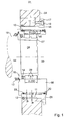
- Fig. 1 to 8 show schematic representations of a longitudinal section through a bearing 01 for a cylinder 02 and a cylinder 02, z. B. forme cylinder 02 or transfer cylinder of an offset printing unit, a rotary printing press in various embodiments.
- the storage 01 for the cylinder 02 includes a first, z. B. outermost, in a bore 03 of a side frame 04 backlash, z. B. pressed, arranged bearing ring 05, a rotatably mounted relative to the first bearing ring 05, a pin 06 of the cylinder 02 receiving and rotationally rigidly connected to the second, z. B. innermost, bearing ring 07.
- As in the example is preferably -. B.
- an eccentric third, z. B. middle, bearing ring 08 is provided.
- the third bearing ring 08 is then z. B. designed to accomplish a (operational) pressure on / off movement relative to an adjacent cylinder eccentric.
- rolling elements are 09; 10 arranged such that the storage 01 is free of play.
- one of the two rolling bearings for example, the outer bearing between the first and third ring
- rolling elements 09; 10 be formed.
- rolling area A; B or generalizes support area A; B is here the length or that longitudinal section of the rolling bearing understood on which or on which the two adjacent bearing rings 05; 07; 08 on each other (via rolling elements 9, 10 or sliding surfaces) support, ie the length in the axial direction between the beginning of first rolling element 09; 10 and the first sliding surface to the end of the last rolling element 09; 10 or the last sliding surface.
- rolling bearings with rolling elements 9; 10 the teaching, in particular for the outer bearing, is applicable to the embodiment as a plain bearing with sliding surfaces in the sense transferred thereto ( Fig. 1 to 8 ).
- At least over the length of the rolling region A between the second bearing ring 07 and third bearing ring 08 (ie, between the innermost and middle bearing ring) arranged rolling elements 09 is provided between the first (outermost) bearing ring 05 and arranged in the side frame 04 bore 03, a gap 11, which an extension of the bearing rings 05; 07; 08 free from exceeding a maximum allowable preload of the bearing rings 05; 07; 08 allowed in the radial direction with each other ( Fig. 1 to 5 ).
- the axial position of the gap 11 in the bearing 01 is preferably such that, in the radial projection, the rolling region A comes to rest within the gap length L.
- the gap 11 extends at least in the projection region of the support A to the full extent.
- the particular arrangement of the gap 11 in the region of the rolling region A of the rolling elements 09; 10 also applicable to Einringlagern, whereby they are also free of external loads and thermal expansion always free of play, without exceeding a maximum allowable preload.
- the first embodiment ( Fig. 1 ) is the first, z. B. outermost, bearing ring 05 on one side of the axially along the rolling range A of the rolling elements 09 extending gap 11, z. B. by pressing, backlash against the bore 03 or supported their wall.
- a radial dimension b of the first bearing ring 05 in the region of the gap 11 extending over the rolling region A is selected such that a predetermined rigidity of the bearing 01 is achieved.
- the radial dimension b of the first bearing ring 05 in the rolling region A of the rolling elements 09 between the second bearing ring 07 and the third bearing ring 08 is between 5 mm and 10 mm.
- the gap 11 has in the radial direction z. B. at least a width a of 0.05 mm, advantageously a width of 0.05 mm to 2.00 mm, in particular up to 1 mm. This width a may also vary slightly in the axial and / or circumferential direction as long as it does not become too small, i. e.g. over 0.02 mm remains.
- a grease chamber 15 can be additionally arranged between the sealing ring 13 and a further sealing ring 14 in order to keep dirt from the storage 01 away. This may also be applied to the remaining examples, unless explicitly excluded.
- the first bearing ring 05 viewed in the axial direction outside of the rolling area A of arranged between the second bearing ring 07 and third bearing ring 08 rolling elements 09 a centering collar 16 on its outer circumference, with the wall of the bore 03 for positionally correct arrangement of the first bearing ring 05 in the bore 03 works together. This simplifies installation and maintenance.
- the centering collar 16 may be designed with clearance or as a pressure.
- the first bearing ring 05 may also have a collar 17 for axial ligation and is by means of fastening means 18, for. B. screws 18 for backup arranged opposite to an axial displacement on the side frame 04.
- fastening means 18 may be used, such as rivets, pins or bolts. This may also be applied to the remaining examples, unless explicitly excluded.
- the first bearing ring 05 and thus arranged in the side frame 04 bore 03 of the bearing 01 have a larger outer diameter than a bale 19 of the cylinder 02. Again, this may, unless explicitly excluded, be applied as an advantageous variant to the other examples ,
- the gap 11 in the radial direction z. B. here also at least a width a of 0.05 mm, advantageously a width a from 0.05 mm to 2.00 mm, in particular up to 1 mm.
- This width a can also vary slightly in the axial and / or circumferential direction, as long as it does not become too small, ie remains above 0.02 mm, for example.
- a third embodiment ( Fig. 3 ) is in contrast to the first two embodiments now over the entire length between the bore 03 and the outer circumference of the outermost bearing ring 05 continuous gap 11th provided, ie no centering collar 16 is provided on the circumference of the outermost bearing ring 05.
- the gap 11 points in the radial direction here z. B. at least a width a of 0.01 mm, advantageously a width a of 0.01 mm to 0.20 mm, in particular to 0.10 mm. This width a may also vary slightly in the axial and / or circumferential direction, as long as it does not become too small, ie in this case, it remains above 0.01 mm.
- a continuous gap 11 between the z. B. metal outside of the outer bearing ring 05 and the z. B. metal inside the bore 03 is provided, but in this gap 11 between these substantially incompressible materials containing a compressible material layer 22, in particular a reversibly compressible layer 22, respectively.
- the gap 11 in at least three angular ranges of the circumference, but preferably fully, completely filled by the compressible layer 22 in the radial direction.
- a width a of the gap 11 is here preferably z. B. at least 0.05 mm, advantageously a width a of 0.05 mm to 2.00 mm, in particular up to 1 mm.
- This width a can also vary slightly in the axial and / or circumferential direction, as long as it does not become too small, ie remains above 0.02 mm, for example.
- the layer 22 is brought into the bore 03 before introduction of the remaining bearing 01.
- Fig. 3 is also here on the circumference of the outermost bearing ring 05 no centering collar 16 is provided.
- a first embodiment of the fifth embodiment can be that of the second example ( Fig. 2 ), wherein, however, a fluid, in particular oil, is arranged in the gap 11 delimiting on both sides by centering collars 16. It can be both sides as in Fig. 5 additionally shown a fluid barrier z. B. in the form of a seal 23, for example, O-ring may be provided.
- the oil-containing gap 11 communicates with a reservoir 25, for example a pressure cell 25, via a passage 24 extending in the side frame 04, for example.
- the oil pressure via the pressure box 25 or other mechanism is adjustable in height.
- the gap 11 has here in the radial direction z. B.
- a width a of 0.05 mm advantageously a width a of 0.05 mm to 2.00 mm, in particular up to 1 mm.
- This width a can also vary slightly in the axial and / or circumferential direction, as long as it does not become too small, ie remains above 0.02 mm, for example.
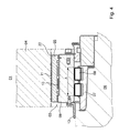
- Fig. 6 shows an embodiment of the bearing 01, wherein the rolling range A of the rolling elements 09 of the rotation of the cylinder 02 enabling radial bearing 07, 08, 09 and the Abisselz- or support region B of the arrival / Abstellterrorism enabling radial bearing 05, 08, 10 of the same Storage 01 do not overlap in the axial direction or viewed offset in relation to each other in the axial direction.
- the middle bearing ring 08 has a length which corresponds to at least the sum of the length of the rolling region A of the inner radial bearing and the rolling or Abstütz Schemes B of the outer radial bearing.
- the part or longitudinal section which carries the inner radial bearing 07, 08, 09 permitting the rotation lies outside the alignment of the side frame 04, in particular on the side of the side frame 04 facing the cylinder 02.
- the middle bearing ring 08 then acts on a cylinder-near side Longitudinal section on its inside with rolling elements 09 of the rotation of the pin 06 enabling radial bearing 07, 08, 09, and on a cylinder remote, and the first-mentioned longitudinal section different longitudinal section on its outer side via rolling elements 10 or sliding surfaces with the outer bearing ring 05 of the pressure on - / Ab-position enabling radial bearing 05, 08, 10 together.
- the pressure on / off position enabling radial bearing is designed as a needle bearing and the rolling elements 10 as needle-like rolling elements. If, if necessary, heat is generated by the rotation and as a result the adjacent area of the middle bearing ring 08 heats up, the cylinder-near end of the middle bearing ring 08 can expand unhindered without being clamped by the outer bearing ring 05 and the side frame 04 and thus to be limited.
- the bearing ring 08 at least in Abicalz Scheme A of the rotation of the pin 06 enabling radial bearing 07, 08, 09 with a substantially constant circumferential wall thickness w (deviation from a minimum wall thickness w at most 10%) is formed.
- the wall thickness w is preferably between 5 mm and 50 mm, in particular between 10 mm and 30 mm.
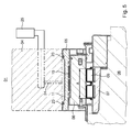
- FIG. 7 and 8th illustrated storage 01 is an example of the opposite to the previous illustrations frame side, z. B. the operating page shown.
- This bearing 01 has between the inner bearing ring 07 and the middle bearing ring 08 in addition to a first bearing portion with the rolling elements 09 axially spaced a second bearing portion with an axially setting bearing 26, z. B. a so-called.
- Axial bearing 26, on. acts with respect to the inner bearing ring 07 stationary tread with a rolling element 27, and this with a respect to the middle bearing ring 08 stationary tread positively against a relative movement in the axial direction together.
- the thrust bearing 26 can either as related to Fig. 6 and 7 on the drive side (eg Fig. 6 ) opposite side (operating side, eg Fig.
- the thrust bearing 26 may advantageously also on the operating side or the drive side (shown) of in Fig. 1 to 5 be provided 01 bearings.
- Fig. 8 is a variant of the execution Fig. 7 shown for the axial setting of the cylinder 02.
- the thrust bearing 26 is pulled further outward than in Fig. 7 ,
- a gap 11 according to one of the embodiments according to Fig. 1 to 5 be provided between the outer bearing ring 05 and the wall of the bore 03.
- the cylinder 02 in the axial direction by an amount ⁇ , e.g. formed by at least ⁇ ⁇ ⁇ 0.5 mm, in particular ⁇ ⁇ 1.0 mm, movable.
- This movement is preferably accommodated in the inner, the rotation permitting radial bearings 07, 08, 09 by the Abracelz Scheme A for the rolling elements 09 on the inside of the middle bearing ring 08 or the outside of the inner bearing ring 07 by at least the amount .DELTA. Is formed wider than that Length between the outer ends of the two outer rolling elements 09 of the bearing.
- the o.g. Gap 11 z. B. over a length of at least the distance between said Wälz stressesau conferencekanten plus the amount ⁇ .
- two eccentrically rotatable rolling elements can be provided which are rotatably mounted on one another via rolling elements.
Landscapes
- Engineering & Computer Science (AREA)
- General Engineering & Computer Science (AREA)
- Mechanical Engineering (AREA)
- Rolling Contact Bearings (AREA)
Abstract
Description
Die Erfindung betrifft Lagerungen eines Zylinders einer Rotationsdruckmaschine gemäß dem Oberbegriff des Anspruchs 1 oder 2.The invention relates to bearings of a cylinder of a rotary printing press according to the preamble of claim 1 or 2.
Durch die
Durch die
Durch die
Durch die
Die
Die
Der Erfindung liegt die Aufgabe zugrunde, Lagerungen eines Zylinders einer Rotationsdruckmaschine zu schaffen.The invention has for its object to provide storage of a cylinder of a rotary printing press.
Die Aufgabe wird erfindungsgemäß durch die Merkmale des Anspruchs 1 oder 2 gelöst.The object is achieved by the features of claim 1 or 2.
Eine Lagerung für einen Zylinder einer Rotationsdruckmaschine umfasst demnach mindestens einen ersten in einer Bohrung eines Seitengestells vorzugsweise spielfrei, z. B. eingepresst, angeordneten Lagerring, sowie mindestens einen gegenüber dem ersten Lagerring drehbar gelagerten, einen Zapfen des Zylinders aufnehmenden zweiten Lagerring, wobei zwischen den Lagerringen innerhalb mindestens eines sich in axialer Richtung erstreckenden Abwälzbereichs Wälzkörper vorzugsweise derart angeordnet sind, dass die Lagerung spielfrei ist. Zumindest auf einer Länge, welche in Axialrichtung betrachtet wenigstens einem Abwälzbereich des Radiallagers entspricht, weist das Lager einen Freiheitsgrad in radialer Richtung nach außen auf, d.h. ist zumindest in diesem Bereich in radialer Richtung nicht durchgängig und spielfrei gegen das Seitengestell abgestützt.A bearing for a cylinder of a rotary printing press therefore preferably comprises at least one first in a bore of a side frame clearance, z. B. pressed, arranged bearing ring, and at least one rotatably mounted relative to the first bearing ring, a pin of the cylinder receiving second bearing ring, wherein between the bearing rings within at least one extending in the axial direction rolling elements rolling elements are preferably arranged such that the bearing is free of play. At least on a length which, viewed in the axial direction, corresponds to at least one rolling region of the radial bearing, the bearing has a degree of freedom in the radially outward direction, i. is at least in this area in the radial direction is not continuous and backlash supported against the side frame.
Dabei ist in einer ersten Ausführung zwischen dem ersten Lagerring und der im Seitengestell angeordneten Bohrung ein sich in axialer Richtung entlang des Abwälzbereichs erstreckender Spalt vorgesehen, welcher ein elastisches Aufweiten des ersten Lagerrings radial von innen nach außen im Abwälzbereich erlaubt, um eine Ausdehnung der Lagerringe in radialer Richtung frei vor Überschreitung einer maximal zulässigen Vorspannung der Lagerringe und der Wälzkörper untereinander zu ermöglichen. Der Spalt erstreckt sich vorzugsweise zumindest auf der gesamten Länge des Abwälzbereichs und in einer vorteilhaften Ausführung vollumfänglich.In this case, in a first embodiment, a gap extending in the axial direction along the rolling area is provided between the first bearing ring and the bore arranged in the side frame, which allows an elastic widening of the first bearing ring radially from the inside to the outside in the rolling region in order to expand the bearing rings radial direction free before exceeding a maximum allow allowable bias of the bearing rings and the rolling elements with each other. The gap preferably extends at least over the entire length of the rolling region and in an advantageous embodiment in its entirety.
In einer anderen Ausführung sind Wirkflächen (Abrollflächen von Wälzkörpern eines Wälzlagers und/oder Gleitflächen eines Gleitlagers) eines die Rotation des Zylinders ermöglichenden Radiallagers und eines die An-/Abstellbewegung ermöglichenden Radiallagers der selben Lagerung in axialer Richtung betrachtet zueinander versetzt angeordnet und/oder ein äußerer Ring des die Rotation des Zylinders ermöglichenden Radiallagers ist mit einer in Umfangsrichtung im wesentlichen konstanten Wandstärke ausgebildet.In another embodiment, active surfaces (rolling surfaces of rolling elements of a roller bearing and / or sliding surfaces of a plain bearing) of a rotation of the cylinder enabling radial bearing and the arrival / Abstellbewegung enabling radial bearing of the same storage in the axial direction are arranged offset to each other and / or an outer Ring of the rotation of the cylinder enabling radial bearing is formed with a circumferentially substantially constant wall thickness.
Die mit der Erfindung erzielbaren Vorteile bestehen insbesondere darin, dass durch den sich in axialer Richtung über den Abwälzbereich erstreckenden Freiheitsgrad (Spalt oder freier Raum) äußere und innere Lasten sowie Wärmeausdehnungen der Lagerung kompensiert werden, ohne dass die Lagerung zu irgendeinem Zeitpunkt Spiel aufweist und ohne dass eine maximal zulässige Vorspannung der Lagerringe untereinander zu irgendeinem Zeitpunkt überschritten wird.The achievable with the present invention consist in particular in that by the extending in the axial direction over the Abwälzbereich degree of freedom (gap or free space) external and internal loads and thermal expansion of the storage are compensated without the storage at any time game and without that a maximum allowable preload of the bearing rings is exceeded each other at any time.
In der ersten Ausführung wird die im Wesentlichen dadurch verwirklicht, dass mindestens ein Lagerring einer Lagerung eines Zylinders einer Rotationsdruckmaschine in einem Abwälzbereich von zwischen einem ersten Lagerring und einem gegenüber dem ersten Lagerring drehbar gelagerten Zapfen angeordneten Wälzkörpern, oder von zwischen einem ersten Lagerring und einem gegenüber einem den Zapfen aufnehmenden zweiten Lagerring angeordneten Wälzkörpern gegenüber dem Zapfen oder gegenüber dem Seitengestell einen Spalt aufweist, welcher ohne dass die Lagerung ihre Spielfreiheit verliert eine Ausdehnung der Lagerringe in radialer Richtung frei von einer Überschreitung einer maximal zulässigen Vorspannung der Lagerringe untereinander erlaubt. In der zweiten Ausführung dadurch, dass Abroll- bzw. Abstützbereich des Radiallagers und der Abstützbereich des Lagers zur An-/Abstellung bezüglich keiner auf der Rotationsachse senkrecht stehenden Ebene überschneiden.In the first embodiment, this is achieved essentially by arranging at least one bearing ring for a bearing of a cylinder of a rotary printing press in a rolling region of rolling elements arranged between a first bearing ring and a pin rotatably mounted with respect to the first bearing ring, or between a first bearing ring and one opposite a journal receiving the second bearing ring arranged rolling elements relative to the pin or with respect to the side frame has a gap which without the storage loses its backlash an expansion of the bearing rings in the radial direction allows free from exceeding a maximum allowable preload of the bearing rings with each other. In the second embodiment in that Abroll- or support area of the radial bearing and the Overlap supporting area of the bearing for on / off with respect to any plane perpendicular to the axis of rotation.
Eine vorteilhafte Ausgestaltung der Lagerung sieht vor, dass zwischen dem ersten und dem zweiten Lagerring mindestens ein dritter Lagerring gegenüber dem ersten und dem zweiten Lagerring drehbar angeordnet ist, wobei sich der Spalt zwischen dem ersten Lagerring und der im Seitengestell angeordneten Bohrung in axialer Richtung über den Abwälzbereich der Wälzkörper zwischen zweitem und drittem Lagerring erstreckt, welcher eine Ausdehnung der Lagerringe frei von einer Überschreitung einer maximal zulässigen Vorspannung der Lagerringe in radialer Richtung untereinander erlaubt. Durch den sich in axialer Richtung über den Abwälzbereich der Wälzkörper zwischen zweitem und dritten Lagerring erstreckenden Spalt können äußere und innere Lasten sowie Wärmeausdehnungen der Lagerung kompensiert werden, ohne dass die Lagerung zu irgendeinem Zeitpunkt Spiel aufweist. Grundsätzlich kann dabei der zweite Lagerring gegenüber dem dritten Lagerring mit Vorspannung oder mit Spiel eingestellt sein. In ersterem Fall gleicht der Spalt innere und äußere Lasten sowie Wärmeausdehnungen zwischen erstem und drittem sowie drittem und zweitem Lagerring, in letzterem Fall zwischen erstem und drittem Lagerring (es könnten auch vier Lagerringe sein) aus.An advantageous embodiment of the bearing provides that between the first and the second bearing ring at least a third bearing ring relative to the first and the second bearing ring is rotatably disposed, wherein the gap between the first bearing ring and the arranged in the side frame bore in the axial direction over the Rolling range of the rolling elements between the second and third bearing ring extends, which allows an expansion of the bearing rings free from exceeding a maximum allowable preload of the bearing rings in the radial direction with each other. By extending in the axial direction over the Abwälzbereich the rolling elements between the second and third bearing ring gap outer and inner loads and thermal expansion of the bearing can be compensated without the storage has at any time game. In principle, the second bearing ring can be adjusted with respect to the third bearing ring with preload or play. In the former case, the gap is similar to internal and external loads and thermal expansions between the first and third and third and second bearing ring, in the latter case between the first and third bearing ring (it could also be four bearing rings).
Der dritte Lagerring kann dabei zur Ermöglichung einer An-/Abstellbewegung zu bzw. von einem benachbarten Zylinder exzenterförmig ausgebildet sein. Hierdurch kann auf besonders einfache Weise durch Verdrehen des dritten Lagerrings eine betriebsmäßige radiale Druck-An-/Ab-Stellung erfolgen. Im Gegensatz zu reinen Montagehilfen zur Abstandseinstellung ist das die drei Lagerringe - und insbesondere zwischen je zwei Ringen Wälzkörper - aufweisende Lager zum betriebsmäßigen Verschwenken ohne nennenswerten Verschleiß ausgelegt. Der exzentrische Lagerring der mindestens drei Ringe steht hierbei mechanisch mit einer fernbetätigbaren Verdreheinrichtung in Wirkverbindung.The third bearing ring can be designed to be eccentric to allow an on / Abstellbewegung to or from an adjacent cylinder. This can be done in a particularly simple manner by rotating the third bearing ring an operational radial pressure on / off position. In contrast to pure assembly aids for distance adjustment that is the three bearing rings - and in particular between each two rings rolling elements - bearing designed for operational pivoting without significant wear. The eccentric bearing ring of the at least three rings is in this case mechanically in operative connection with a remotely operable twisting device.
Vorzugsweise ist der erste Lagerring zumindest einseitig, vorteilhaft in Bezug auf die Steifigkeit jedoch beidseits des sich in axialer Richtung entlang des Abwälzbereichs der Wälzkörper erstreckenden Spalts beispielsweise durch Einpressen vorzugsweise spielfrei gegenüber der Bohrung abgestützt.Preferably, the first bearing ring is supported at least on one side, advantageously with respect to the rigidity, however, on both sides of the gap extending in the axial direction along the rolling region of the rolling elements, for example by pressing, preferably free of play relative to the bore.
Eine andere vorteilhafte Ausgestaltung der Lagerung sieht vor, dass eine radiale Abmessung des ersten Lagerrings im Bereich des sich über den Abwälzbereich erstreckenden Spalts derart gewählt ist, dass eine vorgegebene Steifigkeit der Lagerung erreicht wird. Die radiale Abmessung des ersten Lagerrings im Bereich des sich über den Abwälzbereich erstreckenden Spalts beträgt vorzugsweise 5 mm bis 10 mm.Another advantageous embodiment of the bearing provides that a radial dimension of the first bearing ring in the region of the gap extending over the rolling region is selected such that a predetermined rigidity of the bearing is achieved. The radial dimension of the first bearing ring in the region of the gap extending over the rolling region is preferably 5 mm to 10 mm.
Der Spalt weist vorzugsweise in radialer Richtung eine Weite von 0,1 mm bis 1 mm auf.The gap preferably has a width of 0.1 mm to 1 mm in the radial direction.
Zwischen den Lagerringen können die Abwälzbereiche frei von Verschmutzungen haltende Dichtringe angeordnet sein. Alternativ oder zusätzlich hierzu können zwischen den Lagerringen die Abwälzbereiche frei von Verschmutzungen haltende Fetträume angeordnet sein.Between the bearing rings Abwälzbereiche can be arranged free from dirt holding sealing rings. Alternatively or in addition to this, between the bearing rings, the rolling areas can be arranged free from soiling-holding fat chambers.
Eine besonders vorteilhafte, die Montage und Wartung vereinfachende Lagerung sieht vor, dass der erste Lagerring außerhalb des Abwälzbereichs einen Zentrierbund aufweist, zur positionsrichtigen Anordnung des ersten Lagerrings in der Bohrung. Der Zentrierbund kann mit Spiel oder als Pressung ausgeführt sein.A particularly advantageous, the assembly and maintenance simplifying storage provides that the first bearing ring outside of the rolling range has a centering collar, the positionally correct arrangement of the first bearing ring in the bore. The centering collar can be designed with play or as a pressure.
Vorzugsweise weist der erste Lagerring zur axialen Abbindung einen Kragen auf und ist mittels Schrauben oder Klemmung (z. B. Pratzen) zur Sicherung gegenüber einer axialen Verschiebung am Seitengestell angeordnet.The first bearing ring preferably has a collar for axial setting and is arranged on the side frame by means of screws or clamping (eg claws) for securing against an axial displacement.
Zur Erleichterung einer Demontage des Zylinders und/oder zur Vereinfachung einer Einstellung des Lagerspiels kann der erste Lagerring und damit die in dem Seitengestell angeordnete Bohrung der Lagerung z. B. einen größeren Außendurchmesser aufweisen, als ein Ballen des Zylinders.To facilitate disassembly of the cylinder and / or to facilitate setting of the bearing clearance of the first bearing ring and thus in the side frame arranged bore of the storage z. B. have a larger outer diameter than a bale of the cylinder.
Ausführungsbeispiele der Erfindung sind in den Zeichnungen dargestellt und werden im Folgenden näher beschrieben.Embodiments of the invention are illustrated in the drawings and will be described in more detail below.
Es zeigen:
- Fig. 1
- eine schematische Darstellung eines Längsschnitts durch eine erste Ausführung einer Lagerung für einen Zylinder einer Rotationsdruckmaschine;
- Fig. 2
- eine schematische Darstellung eines Längsschnitts durch eine zweite Ausführung einer Lagerung für einen Zylinder einer Rotationsdruckmaschine;
- Fig. 3
- eine schematische Darstellung eines Längsschnitts durch eine dritte Ausführung einer Lagerung für einen Zylinder einer Rotationsdruckmaschine;
- Fig. 4
- eine schematische Darstellung eines Längsschnitts durch eine vierte Ausführung einer Lagerung für einen Zylinder einer Rotationsdruckmaschine;
- Fig. 5
- eine schematische Darstellung eines Längsschnitts durch eine fünfte Ausführung einer Lagerung für einen Zylinder einer Rotationsdruckmaschine;
- Fig. 6
- eine schematische Darstellung eines Längsschnitts durch eine sechste Ausführung einer Lagerung für einen Zylinder einer Rotationsdruckmaschine;
- Fig. 7
- eine schematische Darstellung eines Längsschnitts durch eine siebte Ausführung einer Lagerung für einen Zylinder einer Rotationsdruckmaschine;
- Fig. 8
- eine schematische Darstellung eines Längsschnitts durch eine achte Ausführung einer Lagerung für einen Zylinder einer Rotationsdruckmaschine.
- Fig. 1
- a schematic representation of a longitudinal section through a first embodiment of a storage for a cylinder of a rotary printing machine;
- Fig. 2
- a schematic representation of a longitudinal section through a second embodiment of a storage for a cylinder of a rotary printing machine;
- Fig. 3
- a schematic representation of a longitudinal section through a third embodiment of a storage for a cylinder of a rotary printing machine;
- Fig. 4
- a schematic representation of a longitudinal section through a fourth embodiment of a storage for a cylinder of a rotary printing machine;
- Fig. 5
- a schematic representation of a longitudinal section through a fifth embodiment of a storage for a cylinder of a rotary printing machine;
- Fig. 6
- a schematic representation of a longitudinal section through a sixth embodiment of a storage for a cylinder of a rotary printing machine;
- Fig. 7
- a schematic representation of a longitudinal section through a seventh embodiment of a storage for a cylinder of a rotary printing machine;
- Fig. 8
- a schematic representation of a longitudinal section through an eighth embodiment of a storage for a cylinder of a rotary printing press.
Zwischen den Lagerringen 05; 07; 08 innerhalb eines sich in axialer Richtung erstreckenden Abstützbereichs A; B, z.B. Abwälzbereich A; B, sind Wälzkörper 09; 10 derart angeordnet, dass die Lagerung 01 spielfrei ist. Anstelle von Wälzlagern kann eines der beiden Wälzlager (z. B. das äußere Lager zwischen erstem und drittem Ring) ggf. auch als Gleitlager mit Gleitflächen anstelle von Wälzkörpern 09; 10 ausgebildet sein. Als Abwälzbereich A; B bzw. verallgemeinert Abstützbereich A; B wird hier diejenige Länge oder derjenige Längsabschnitt des Wälzlagers verstanden, auf welcher bzw. auf welchem sich die beiden benachbarten Lagerringe 05; 07; 08 aufeinander (über Wälzkörper 9; 10 oder Gleitflächen) abstützen, d.h. die Länge in axialer Richtung zwischen dem Anfang des ersten Wälzkörpers 09; 10 bzw. der ersten Gleitfläche bis zum Ende des letzten Wälzkörpers 09; 10 bzw. der letzten Gleitfläche. Im Folgenden werden die Beispiele der Einfachheit halber für den Fall von Wälzlagern mit Wälzkörpern 9; 10 beschrieben, wobei jedoch die Lehre, insbesondere für das äußere Lager, auf die Ausführung als Gleitlager mit Gleitflächen im hierauf übertragenen Sinne anzuwenden ist (
Zumindest auf der Länge des Abwälzbereichs A der zwischen zweitem Lagerring 07 und drittem Lagerring 08 (d.h. zwischen innerstem und mittlerem Lagerring) angeordneten Wälzkörper 09 ist zwischen dem ersten (äußersten) Lagerring 05 und der im Seitengestell 04 angeordneten Bohrung 03 ein Spalt 11 vorgesehen, welcher eine Ausdehnung der Lagerringe 05; 07; 08 frei von einer Überschreitung einer maximal zulässigen Vorspannung der Lagerringe 05; 07; 08 in radialer Richtung untereinander erlaubt (
Grundsätzlich ist die besondere Anordnung des Spalts 11 im Bereich des Abwälzbereichs A der Wälzkörper 09; 10 auch bei Einringlagern anwendbar, wodurch diese ebenso frei von äußeren Lasten und Wärmeausdehnung immer spielfrei sind, ohne eine maximal zulässige Vorspannung zu überschreiten.In principle, the particular arrangement of the
Im ersten Ausführungsbeispiel (
Eine radiale Abmessung b des ersten Lagerrings 05 im Bereich des sich über den Abwälzbereich A erstreckenden Spalts 11 ist derart gewählt, dass eine vorgegebene Steifigkeit der Lagerung 01 erreicht wird. Die radiale Abmessung b des ersten Lagerrings 05 im Abwälzbereich A der Wälzkörper 09 zwischen zweitem Lagerring 07 und drittem Lagerring 08 beträgt zwischen 5 mm und 10 mm. Der Spalt 11 weist in radialer Richtung z. B. mindestens eine Weite a von 0,05 mm, vorteilhaft eine Weite von 0,05 mm bis 2,00 mm, insbesondere bis 1 mm auf. Diese Weite a kann in axialer und/oder Umfangsrichtung auch leicht variieren, solange sie nicht zu klein wird, d.h. z.B. über 0,02 mm bleibt.A radial dimension b of the
Zwischen den Lagerringen 05; 07; 08 sind die Abwälzbereiche A; B frei von Verschmutzungen haltende Dichtringe 12; 13; 20 angeordnet. Zwischen zweitem Lagerring 07 und drittem Lagerring 08 kann zusätzlich zwischen dem Dichtring 13 und einem weiteren Dichtring 14 ein Fettraum 15 angeordnet sein, um Verschmutzungen aus der Lagerung 01 fern zu halten. Dies kann auch, wo nicht explizit ausgenommen, auf die übrigen Beispiele angewandt sein.Between the bearing rings 05; 07; 08 are the rolling areas A; B free from contamination holding seals 12; 13; 20 arranged. Between the
Der erste Lagerring 05 weist in axialer Richtung betrachtet außerhalb des Abwälzbereichs A der zwischen zweitem Lagerring 07 und drittem Lagerring 08 angeordneten Wälzkörper 09 einen Zentrierbund 16 auf seinem Außenumfang auf, der mit der Wandung der Bohrung 03 zur positionsrichtigen Anordnung des ersten Lagerrings 05 in der Bohrung 03 zusammen wirkt. Hierdurch wird Montage und Wartung vereinfacht. Durch das Ineinandergreifen von Zentrierbund 16 und Bohrung 03 erfolgt eine formschlüssige Verbindung gegen ein Bewegen in radialer Richtung. Der Zentrierbund 16 kann mit Spiel oder als Pressung ausgeführt sein.The
Der erste Lagerring 05 kann darüber hinaus zur axialen Abbindung einen Kragen 17 aufweisen und ist mittels Befestigungsmittel 18, z. B. Schrauben 18 zur Sicherung gegenüber einer axialen Verschiebung am Seitengestell 04 angeordnet. Anstelle von Schrauben 18 können auch andere geeignete Befestigungsmittel 18 verwendet werden, etwa Nieten, Stifte oder Bolzen. Dies kann auch, wo nicht explizit ausgenommen, auf die übrigen Beispiele angewandt sein.The
Zur Erleichterung einer Demontage des Zylinders 02 und/oder zur Vereinfachung einer Einstellung des Lagerspiels kann z. B. der erste Lagerring 05 und damit die in dem Seitengestell 04 angeordnete Bohrung 03 der Lagerung 01 einen größeren Außendurchmesser aufweisen, als ein Ballen 19 des Zylinders 02. Auch dies kann, wo nicht explizit ausgenommen, als vorteilhafte Variante auf die übrigen Beispiele angewandt sein.To facilitate disassembly of the
Im Folgenden werden für die vergleichbaren und/oder gleichwirkenden Teile die selben Bezugszeichen beibehalten.In the following, the same reference numerals are retained for the comparable and / or equivalent parts.
In der Ausgestaltung eines zweiten Ausführungsbeispiels (
In der Ausgestaltung eines dritten Ausführungsbeispiels (
In der Ausgestaltung eines vierten Ausführungsbeispiels (
Eine erste Ausgestaltung des fünften Ausführungsbeispiels (
In einer zweiten Ausgestaltung des fünften Ausführungsbeispiels kann anstelle der beiden Zentrierbunde 16 im Bereich der beiden stirnseitigen Enden des äußeren Lagerrings 05 anstelle der Zentrierbunde 16 lediglich eine Verjüngung des Spaltes 11 - z. B. auf lediglich 0,01 - 0,05 mm Spaltbreite - vorgesehen sein, wobei z.B. im Bereich dieser Verjüngung wieder jeweils eine Dichtung 23, z. B. ein O-Ring, vorgesehen ist. Im mittleren, zwischen den endnahen Verjüngungen liegenden Bereich liegt z.B. eine Weite a von mindestens 0,05 mm, vorteilhaft eine Weite a von 0,05 mm bis 2,00 mm, insbesondere bis 1 mm vor. Auch hier kann diese Weite a in axialer und/oder Umfangsrichtung leicht variieren, solange sie nicht zu klein wird, d.h. z.B. über 0,02 mm bleibt.In a second embodiment of the fifth embodiment, instead of the two centering
In vorteilhafter Ausbildung ist der Lagerring 08 zumindest im Abwälzbereich A des die Rotation des Zapfens 06 ermöglichenden Radiallagers 07, 08, 09 mit einer im wesentlichen in Umfangsrichtung konstanten Wandstärke w (Abweichung von einer kleinsten Wandstärke w höchstens 10 %) ausgebildet. Hierdurch werden symmetrische Bedingungen für thermische Effekte geschaffen. Die Wandstärke w liegt hier vorzugsweise zwischen 5 mm und 50 mm, insbesondere zwischen 10 mm und 30 mm.In an advantageous embodiment, the bearing
Die in
In
Für die Ausführung nach
In einer besonderen Ausbildung des Zylinders 02 der vorausgehenden Ausführungsbeispiele, z. B. als Formzylinder 02, ist der Zylinder 02 in axialer Richtung um einen Betrag Δ, z.B. um mindestens Δ ≥ ± 0,5 mm, insbesondere ≥ ± 1,0 mm, bewegbar ausgebildet. Diese Bewegung wird vorzugsweise im inneren, die Rotation ermöglichenden Radiallager 07, 08, 09 aufgenommen, indem der Abwälzbereich A für die Wälzkörper 09 auf der Innenseite des mittleren Lagerrings 08 oder der Außenseite des inneren Lagerrings 07 um mindestens den Betrag Δ breiter ausgebildet ist als die Länge zwischen den äußeren Enden der beiden äußeren Wälzkörper 09 des Lagers. In diesem Fall verläuft der o.g. Spalt 11 z. B. über eine Länge von mindesten dem Abstand zwischen den genannten Wälzkörperaußenkanten zuzüglich dem Betrag Δ.In a particular embodiment of the
In Weiterbildung können anstelle des einen exzentrischen Lagerringes 08 (Zwischenring) zwei exzentrisch drehbar über Wälzkörper ineinander gelagerte Zwischenringe vorgesehen sein.In a further development, instead of the one eccentric bearing ring 08 (intermediate ring), two eccentrically rotatable rolling elements can be provided which are rotatably mounted on one another via rolling elements.
- 0101
- Lagerungstorage
- 0202
- Zylinder, FormzylinderCylinder, forme cylinder
- 0303
- Bohrungdrilling
- 0404
- Seitengestellside frame
- 0505
- Lagerring, ersterBearing ring, first
- 0606
- Zapfenspigot
- 0707
- Lagerring, zweiterBearing ring, second
- 0808
- Lagerring, dritterBearing ring, third
- 0909
- Wälzkörperrolling elements
- 1010
- Wälzkörperrolling elements
- 1111
- Spaltgap
- 1212
- Dichtringseal
- 1313
- Dichtringseal
- 1414
- Dichtringseal
- 1515
- Fettraumgrease chamber
- 1616
- Zentrierbundspigot
- 1717
- Kragencollar
- 1818
- Befestigungsmittel, SchraubeFastener, screw
- 1919
- Ballenbale
- 2020
- Dichtringseal
- 2121
- Klemmeinrichtung, KlemmringClamping device, clamping ring
- 2222
- Schichtlayer
- 2323
- Dichtungpoetry
- 2424
- Kanalchannel
- 2525
- Reservoir, DruckdoseReservoir, pressure box
- 2626
- Lager, AxiallagerBearing, thrust bearing
- 2727
- Wälzkörperrolling elements
- AA
- Abstützbereich, AbwälzbereichSupporting area, rolling area
- BB
- Abstützbereich, AbwälzbereichSupporting area, rolling area
- LL
- Spalt, LängeGap, length
- aa
- Weitewidth
- bb
- Abmessung, radialeDimension, radial
- ww
- WandstärkeWall thickness
Claims (22)
Applications Claiming Priority (2)
| Application Number | Priority Date | Filing Date | Title |
|---|---|---|---|
| DE102007020217A DE102007020217B4 (en) | 2007-04-28 | 2007-04-28 | Storage of a cylinder of a rotary printing machine |
| DE102008000204A DE102008000204B4 (en) | 2008-01-31 | 2008-01-31 | Storage for a cylinder of a rotary printing machine |
Publications (1)
| Publication Number | Publication Date |
|---|---|
| EP1990192A2 true EP1990192A2 (en) | 2008-11-12 |
Family
ID=39769568
Family Applications (1)
| Application Number | Title | Priority Date | Filing Date |
|---|---|---|---|
| EP08154589A Withdrawn EP1990192A2 (en) | 2007-04-28 | 2008-04-16 | Cylinder bearings in a rotary printing press |
Country Status (1)
| Country | Link |
|---|---|
| EP (1) | EP1990192A2 (en) |
Cited By (7)
| Publication number | Priority date | Publication date | Assignee | Title |
|---|---|---|---|---|
| WO2011085831A1 (en) | 2010-01-14 | 2011-07-21 | Koenig & Bauer Aktiengesellschaft | Device for bearing one or more cylinders of a printing press |
| DE102010000891A1 (en) | 2010-01-14 | 2011-07-21 | KOENIG & BAUER Aktiengesellschaft, 97080 | Device for mounting cylinder of printing machine in side frame, has bearing outer ring, which directly or indirectly receives radial bearing and is mounted in opening of side frame |
| DE102010030331A1 (en) | 2010-06-22 | 2011-12-22 | Koenig & Bauer Aktiengesellschaft | Device for bearing cylinder of printing press in side frame, has inner ring of radial bearing for receiving journal of cylinder which is arranged directly over bearing unit in outer ring enabling radial movement of journal |
| CN102312925A (en) * | 2011-08-05 | 2012-01-11 | 中国科学院光电技术研究所 | Method for fixing thrust bearing ring |
| US8292509B2 (en) | 2009-03-25 | 2012-10-23 | Rolls-Royce Plc | Bearing arrangement |
| DE102011082679A1 (en) | 2011-09-14 | 2013-03-14 | Koenig & Bauer Aktiengesellschaft | Device for fixing and adjusting bearing device of printing cylinder at side frame of printing machine, has clamping elements which are arranged at side frame of printing machine and are clamped with bearing base |
| DE102013213511A1 (en) | 2013-07-10 | 2015-01-15 | Koenig & Bauer Aktiengesellschaft | Sealing device for a radial bearing and bearing device for a rotary body of a printing press |
Citations (6)
| Publication number | Priority date | Publication date | Assignee | Title |
|---|---|---|---|---|
| EP0614759A1 (en) | 1993-03-12 | 1994-09-14 | M.A.N.-ROLAND Druckmaschinen Aktiengesellschaft | Method and device for adjusting printing cylinders |
| EP0706880A2 (en) | 1994-10-13 | 1996-04-17 | Koenig & Bauer Aktiengesellschaft | Bearing bush |
| DE10014040A1 (en) | 1999-11-23 | 2001-05-31 | Koenig & Bauer Ag | Shaft for synchronising positioning movement of servo gears in rotary printing machine is shorter than distance between side frames to which it is connected by bore and bearing journal |
| WO2001038093A1 (en) | 1999-11-26 | 2001-05-31 | Koenig & Bauer Aktiengesellschaft | Arrangement of bearings pertaining to a cylinder of a rotary printing press |
| DE10021233A1 (en) | 2000-04-29 | 2001-10-31 | Schaeffler Waelzlager Ohg | Combined mounting for shaft journal of a printing cylinder or drum has roller bearings, intermediate ring, bearing housing, inner and outer tracks, control, cam disc |
| DE102004035387B4 (en) | 2004-07-21 | 2006-11-09 | Ab Skf | Cylindrical roller bearings |
-
2008
- 2008-04-16 EP EP08154589A patent/EP1990192A2/en not_active Withdrawn
Patent Citations (6)
| Publication number | Priority date | Publication date | Assignee | Title |
|---|---|---|---|---|
| EP0614759A1 (en) | 1993-03-12 | 1994-09-14 | M.A.N.-ROLAND Druckmaschinen Aktiengesellschaft | Method and device for adjusting printing cylinders |
| EP0706880A2 (en) | 1994-10-13 | 1996-04-17 | Koenig & Bauer Aktiengesellschaft | Bearing bush |
| DE10014040A1 (en) | 1999-11-23 | 2001-05-31 | Koenig & Bauer Ag | Shaft for synchronising positioning movement of servo gears in rotary printing machine is shorter than distance between side frames to which it is connected by bore and bearing journal |
| WO2001038093A1 (en) | 1999-11-26 | 2001-05-31 | Koenig & Bauer Aktiengesellschaft | Arrangement of bearings pertaining to a cylinder of a rotary printing press |
| DE10021233A1 (en) | 2000-04-29 | 2001-10-31 | Schaeffler Waelzlager Ohg | Combined mounting for shaft journal of a printing cylinder or drum has roller bearings, intermediate ring, bearing housing, inner and outer tracks, control, cam disc |
| DE102004035387B4 (en) | 2004-07-21 | 2006-11-09 | Ab Skf | Cylindrical roller bearings |
Cited By (11)
| Publication number | Priority date | Publication date | Assignee | Title |
|---|---|---|---|---|
| US8292509B2 (en) | 2009-03-25 | 2012-10-23 | Rolls-Royce Plc | Bearing arrangement |
| WO2011085831A1 (en) | 2010-01-14 | 2011-07-21 | Koenig & Bauer Aktiengesellschaft | Device for bearing one or more cylinders of a printing press |
| DE102010000891A1 (en) | 2010-01-14 | 2011-07-21 | KOENIG & BAUER Aktiengesellschaft, 97080 | Device for mounting cylinder of printing machine in side frame, has bearing outer ring, which directly or indirectly receives radial bearing and is mounted in opening of side frame |
| DE102010000891B4 (en) * | 2010-01-14 | 2014-03-06 | Koenig & Bauer Aktiengesellschaft | Devices for the storage of printing cylinders of a printing machine |
| DE102010030331A1 (en) | 2010-06-22 | 2011-12-22 | Koenig & Bauer Aktiengesellschaft | Device for bearing cylinder of printing press in side frame, has inner ring of radial bearing for receiving journal of cylinder which is arranged directly over bearing unit in outer ring enabling radial movement of journal |
| CN102312925A (en) * | 2011-08-05 | 2012-01-11 | 中国科学院光电技术研究所 | Method for fixing thrust bearing ring |
| CN102312925B (en) * | 2011-08-05 | 2013-03-06 | 中国科学院光电技术研究所 | Method for fixing thrust bearing ring |
| DE102011082679A1 (en) | 2011-09-14 | 2013-03-14 | Koenig & Bauer Aktiengesellschaft | Device for fixing and adjusting bearing device of printing cylinder at side frame of printing machine, has clamping elements which are arranged at side frame of printing machine and are clamped with bearing base |
| DE102011082679B4 (en) * | 2011-09-14 | 2014-07-03 | Koenig & Bauer Aktiengesellschaft | Device and method for fastening and / or adjusting a bearing device of a printing cylinder |
| DE102013213511A1 (en) | 2013-07-10 | 2015-01-15 | Koenig & Bauer Aktiengesellschaft | Sealing device for a radial bearing and bearing device for a rotary body of a printing press |
| DE102013213511B4 (en) * | 2013-07-10 | 2015-11-05 | Koenig & Bauer Ag | Bearing device for a rotary body of a printing press |
Similar Documents
| Publication | Publication Date | Title |
|---|---|---|
| DE102008000204B4 (en) | Storage for a cylinder of a rotary printing machine | |
| EP1990192A2 (en) | Cylinder bearings in a rotary printing press | |
| EP3247923B1 (en) | Transmission and method for adjusting the circumferential backlash of the transmission | |
| EP0239830B1 (en) | Device for adjusting the relative rotational position between a toothed wheel and a coaxal toothed crown | |
| DE60101537T2 (en) | Cam mechanism with crossed roller bearings | |
| EP1668263B1 (en) | Pivot bearing arrangement of a rotational body | |
| DE2360188C2 (en) | Rotation lock on bearings for the rolls of roll stands | |
| EP1155829A2 (en) | Exchangeable cylinder element in an electrographic printing unit | |
| DE4216306C2 (en) | Rotary transmitter for printing machines | |
| DE3643295A1 (en) | Three-ring bearing | |
| DE19860643A1 (en) | Rolling element screw drive and method for its assembly | |
| EP1322474B1 (en) | Bearing for a cylinder or drum in a printing machine | |
| DE4326150C2 (en) | Device for the axial fixing of components | |
| DE10033894A1 (en) | Disassembly device for a self-adjusting bearing | |
| WO2008034417A2 (en) | Bearing unit for axial shaft positioning | |
| DE102011007494B4 (en) | Concept for providing a contact shoulder in a cylindrical bearing housing | |
| DE102007020217B4 (en) | Storage of a cylinder of a rotary printing machine | |
| WO1995001477A1 (en) | Device for evacuating condensate from a fluted drying cylinder by means of condensate evacuation pipes | |
| DE69611519T2 (en) | REGENERATIVE HEAT EXCHANGER AND METHOD FOR OPERATING A REGENERATIVE HEAT EXCHANGER | |
| DE102008063117B4 (en) | Printing machine bearing arrangement | |
| DE69531073T2 (en) | locking nut | |
| DE102005062649A1 (en) | Roller bearing for use in e.g. shaft, has outer ring that includes recess running transverse to circumferential direction and that is formed as open ring, where diameter of outer ring is varied by axial lining of pin rollers | |
| EP2582522B1 (en) | Mounting for the main cylinders of printing presses | |
| CH687603A5 (en) | Arrangement for adjusting the bearing clearance for cylinders of printing presses. | |
| DE7338366U (en) | Split cylindrical roller bearing |
Legal Events
| Date | Code | Title | Description |
|---|---|---|---|
| PUAI | Public reference made under article 153(3) epc to a published international application that has entered the european phase |
Free format text: ORIGINAL CODE: 0009012 |
|
| AK | Designated contracting states |
Kind code of ref document: A2 Designated state(s): AT BE BG CH CY CZ DE DK EE ES FI FR GB GR HR HU IE IS IT LI LT LU LV MC MT NL NO PL PT RO SE SI SK TR |
|
| AX | Request for extension of the european patent |
Extension state: AL BA MK RS |
|
| STAA | Information on the status of an ep patent application or granted ep patent |
Free format text: STATUS: THE APPLICATION HAS BEEN WITHDRAWN |
|
| 18W | Application withdrawn |
Effective date: 20120419 |