EP1988337A2 - Vorrichtung zur Vermeidung selbsterregter Verbrennungsschwingungen - Google Patents
Vorrichtung zur Vermeidung selbsterregter Verbrennungsschwingungen Download PDFInfo
- Publication number
- EP1988337A2 EP1988337A2 EP08007820A EP08007820A EP1988337A2 EP 1988337 A2 EP1988337 A2 EP 1988337A2 EP 08007820 A EP08007820 A EP 08007820A EP 08007820 A EP08007820 A EP 08007820A EP 1988337 A2 EP1988337 A2 EP 1988337A2
- Authority
- EP
- European Patent Office
- Prior art keywords
- combustion chamber
- cylindrical
- combustion
- burner
- excited
- Prior art date
- Legal status (The legal status is an assumption and is not a legal conclusion. Google has not performed a legal analysis and makes no representation as to the accuracy of the status listed.)
- Granted
Links
Images
Classifications
-
- F—MECHANICAL ENGINEERING; LIGHTING; HEATING; WEAPONS; BLASTING
- F23—COMBUSTION APPARATUS; COMBUSTION PROCESSES
- F23M—CASINGS, LININGS, WALLS OR DOORS SPECIALLY ADAPTED FOR COMBUSTION CHAMBERS, e.g. FIREBRIDGES; DEVICES FOR DEFLECTING AIR, FLAMES OR COMBUSTION PRODUCTS IN COMBUSTION CHAMBERS; SAFETY ARRANGEMENTS SPECIALLY ADAPTED FOR COMBUSTION APPARATUS; DETAILS OF COMBUSTION CHAMBERS, NOT OTHERWISE PROVIDED FOR
- F23M9/00—Baffles or deflectors for air or combustion products; Flame shields
- F23M9/06—Baffles or deflectors for air or combustion products; Flame shields in fire-boxes
Definitions
- the invention relates to a device for avoiding self-excited combustion oscillations in substantially cylindrical combustion chambers.
- the invention is therefore based on the object to achieve a device for preventing self-excited combustion oscillations in cylindrical combustion chambers, which is characterized by simple construction and the avoidance of increased flow resistance.
- the cylindrical tube has a diameter of 40% to 60% of the diameter of the combustion chamber and a height of 30% to 50% of the height of the combustion chamber.
- the cylindrical tube has a diameter of 100% to 160% of the diameter of the burner and a height of 90% to 200% of the height of the burner.
- spacers between the tube and the combustion chamber can provide for a firm positioning of the tube. If there are recesses at the lower end of the cylindrical tube, condensate can flow through them.
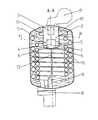
- FIG. 1 shows a cylindrical combustion chamber 2, which is located in a water jacket 9.
- the combustion chamber 2 has an axis of symmetry 4.
- a burner 3 which is also arranged around the same axis of symmetry 4.
- the burner 3 is supplied via a blower 7 with air and fuel.
- From the combustion chamber 2 open two exhaust gas inlets 11 in spiral exhaust pipes 10, which pass through the water jacket 9 and then into an exhaust manifold 8, which is followed by an exhaust pipe, not shown, open.
- a condensate drain 12 At the lowest end of the cylindrical combustion chamber 2 is a condensate drain 12, which also opens into the exhaust manifold 8 with integrated siphon.
- a cylindrical tube 1 In the lower region of the cylindrical combustion chamber 2 opposite to the burner 3 is a cylindrical tube 1, which is arranged by spacers 5 positioned from the walls of the cylindrical combustion chamber 2. In the lower part of the cylindrical tube 1 are recesses 6.
- a fuel gas-air mixture flows through the fan 7 in the burner 3.
- On the outer surface of the burner 3 burns the fuel gas-air mixture within the combustion chamber 2.
- the exhaust gases flow through the exhaust gas inlet 11 into the exhaust pipes 10 and give off thermal energy to the water jacket 9.
- the cooled exhaust gases of the burner 3 are discharged via the exhaust manifold 8 and the subsequent exhaust pipe into the environment. If the dew point of the exhaust gas falls below within the combustion chamber 2, condensate is formed which flows downwards on the walls of the combustion chamber 2. Through the recesses 6 in the cylindrical tube 2, this condensate flows to the condensate drain 12 in the siphon of the exhaust manifold 8 and from there into a sewer.
- the cylindrical tube 1 prevents the formation of standing acoustic waves in the combustion chamber 2, which lead to self-excited combustion oscillations.
Landscapes
- Engineering & Computer Science (AREA)
- Chemical & Material Sciences (AREA)
- Combustion & Propulsion (AREA)
- Mechanical Engineering (AREA)
- General Engineering & Computer Science (AREA)
- Gas Burners (AREA)
- Fluidized-Bed Combustion And Resonant Combustion (AREA)
- Combustion Of Fluid Fuel (AREA)
Abstract
Description
- Die Erfindung bezieht sich auf eine Vorrichtung zur Vermeidung selbsterregter Verbrennungsschwingungen bei im Wesentlichen zylindrischen Brennkammern.
- Bei vollvormischenden Verbrennungssystemen können selbsterregte Verbrennungsschwingungen auftreten, die mit unangenehmen Geräuschen verbunden sind. Die Frequenzen ergeben sich aus der Geometrie der Verbrennungsvorrichtung. Da die selbsterregten Verbrennungsschwingungen durch die Stoffströme, deren Temperatur als auch die Geometrie des Systems bedingt sind, lässt sich das System beispielsweise dadurch verstimmen und somit das unangenehme Geräusch beseitigen, indem die Verbrennungsparameter verändert werden. Da Gasbrenner zumeist mit einem bestimmten Luftüberschuss betrieben werden, ist es möglich, dass Brenngas-Luft-Verhältnis durch die Zugabe oder Verminderung des Luftanteils zu verändern und hierdurch eine akustische Verstimmung zu erreichen. Dies setzt einen automatischen oder manuellen Eingriff in die Gemischregelung voraus. Es sind auch Maßnahmen bekannt, bei denen durch den Einsatz von Drosseln stehende Wellen gebrochen werden. Dies hat jedoch den Nachteil, dass das System über einen erhöhten Strömungswiderstand verfügt und somit die benötigte elektrische Leistung für das Verbrennungsgebläse erhöht wird.
- Der Erfindung liegt daher die Aufgabe zugrunde, eine Vorrichtung zur Vermeidung selbsterregter Verbrennungsschwingungen bei zylindrischen Brennkammern zu erreichen, welche sich durch einfachen Aufbau und die Vermeidung erhöhter Strömungswiderstände auszeichnet.
- Diese Aufgabe wird gemäß den Ansprüchen des unabhängigen Vorrichtungsanspruchs 1 dadurch gelöst, dass in der zylindrischen Brennkammer ein zylindrisches Rohr gegenüber dem Brenner angeordnet wird. Hierbei sind die Brennkammer und das zylindrische Rohr zumindest annähernd um die gleiche Symmetrieachse angeordnet.
- Vorteilhafte Ausgestaltungen ergeben sich durch die Merkmale der abhängigen Vorrichtungsansprüche. So ist es als besonders vorteilhaft anzusehen, wenn das zylindrische Rohr einen Durchmesser von 40% bis 60% des Durchmessers der Brennkammer sowie eine Höhe von 30% bis 50% der Höhe der Brennkammer besitzt. Bezogen auf den Brenner ist es vorteilhaft, wenn das zylindrische Rohr einen Durchmesser von 100% bis 160% des Durchmessers des Brenners sowie eine Höhe von 90% bis 200% der Höhe des Brenners besitzt. Optional können Abstandshalter zwischen dem Rohr und der Brennkammer für eine feste Positionierung des Rohres sorgen. Befinden sich am unteren Ende des zylindrischen Rohres Aussparungen, so kann Kondensat durch diese hindurchfließen.
- Die Erfindung wird nun anhand der Figuren detailliert erläutert. Hierbei zeigen
-
Fig. 1 einen Querschnitt durch ein Heizgerät mit zylindrischer Brennkammer sowie - Fig. 2 einen Horizontalschnitt durch dieselbe Vorrichtung.
-
Figur 1 zeigt eine zylindrische Brennkammer 2, welche sich in einem Wassermantel 9 befindet. Die Brennkammer 2 verfügt über eine Symmetrieachse 4. Am oberen Ende der zylindrischen Brennkammer 2 befindet sich ein Brenner 3, der ebenfalls um die gleiche Symmetrieachse 4 angeordnet ist. Der Brenner 3 wird über ein Gebläse 7 mit Luft und Brennstoff versorgt. Von der Brennkammer 2 münden zwei Abgaseintritte 11 in spiralförmige Abgasrohre 10, welche den Wassermantel 9 durchziehen und anschließend in einen Abgassammler 8, dem sich eine nicht dargestellt Abgasleitung anschließt, münden. Am untersten Ende der zylindrischen Brennkammer 2 befindet sich ein Kondensatablauf 12, welcher ebenfalls in den Abgassammler 8 mit integriertem Siphon mündet. Im unteren Bereich der zylindrischen Brennkammer 2 gegenüber des Brenners 3 befindet sich ein zylindrisches Rohr 1, welches durch Abstandshalter 5 von den Wänden der zylindrischen Brennkammer 2 positioniert angeordnet ist. Im unteren Bereich des zylindrischen Rohres 1 befinden sich Aussparungen 6. - Beim Betrieb der Vorrichtung strömt ein Brenngas-Luft-Gemisch über das Gebläse 7 in den Brenner 3. An der Außenoberfläche des Brenners 3 verbrennt das Brenngas-Luft-Gemisch innerhalb der Brennkammer 2. Die Abgase strömen durch den Abgaseintritt 11 in die Abgasrohre 10 und geben dabei thermische Energie auf den Wassermantel 9 ab. Die abgekühlten Abgase des Brenners 3 werden über den Abgassammler 8 und die sich anschließende Abgasleitung in die Umgebung abgeführt. Wird innerhalb der Brennkammer 2 der Taupunkt des Abgases unterschritten, so entsteht Kondensat, welches an den Wänden der Brennkammer 2 nach unten fließt. Durch die Aussparungen 6 im zylindrischen Rohr 2 strömt dieses Kondensat zum Kondensatablauf 12 in den Siphon des Abgassammlers 8 und von dort in einen Abwasserkanal.
- Das zylindrische Rohr 1 verhindert die Entstehung stehender akustischer Wellen in der Brennkammer 2, welche zu selbsterregten Verbrennungsschwingungen führen.
Claims (7)
- Vorrichtung zur Vermeidung selbsterregter Verbrennungsschwingungen bei einer zumindest annähernd zylindrischen Brennkammer (2) mit einem zylindrischen Brenner (3), welcher zumindest annähernd zentrisch um die Symmetrieachse (4) der zylindrischen Brennkammer (2) an einer Seite der Brennkammer (2) angeordnet ist, wobei radial um den Brenner (2) angeordnete Abgaseintritte (11) von der Brennkammer (2) in einen Wassermantel (9) durchziehende Abgasrohre (10) münden, dadurch gekennzeichnet, dass die Vorrichtung zur Vermeidung selbsterregter Verbrennungsschwingungen aus einem zylindrischen Rohr (1) besteht, welches auf der dem Brenner (2) gegenüberliegenden Seite der Brennkammer (2) zumindest annähernd zentrisch um die Symmetrieachse (4) der zylindrischen Brennkammer (2) im Totwassergebiet der Abgase angeordnet ist.
- Vorrichtung zur Vermeidung selbsterregter Verbrennungsschwingungen (1) bei einer zumindest annähernd zylindrischen Brennkammer (2) nach Anspruch 1, dadurch gekennzeichnet, dass das zylindrische Rohr (1) einen Durchmesser von 40 bis 60 % des Durchmessers der Brennkammer (2) besitzt.
- Vorrichtung zur Vermeidung selbsterregter Verbrennungsschwingungen bei einer zumindest annähernd zylindrischen Brennkammer (2) nach einem der Ansprüche 1 oder 2, dadurch gekennzeichnet, dass das zylindrische Rohr (1) eine Höhe von 30 bis 50 % der Höhe der Brennkammer (2) besitzt.
- Vorrichtung zur Vermeidung selbsterregter Verbrennungsschwingungen bei einer zumindest annähernd zylindrischen Brennkammer (2) nach einem der Ansprüche 1 bis 3, dadurch gekennzeichnet, dass das zylindrische Rohr (1) einen Durchmesser von 100 bis 160 % des Durchmessers des Brenners (3) besitzt.
- Vorrichtung zur Vermeidung selbsterregter Verbrennungsschwingungen bei einer zumindest annähernd zylindrischen Brennkammer (2) nach einem der Ansprüche 1 bis 4, dadurch gekennzeichnet, dass das zylindrische Rohr (1) eine Höhe von 90 bis 200 % der Höhe des Brenners (3) besitzt.
- Vorrichtung zur Vermeidung selbsterregter Verbrennungsschwingungen bei einer zumindest annähernd zylindrischen Brennkammer (2) nach einem der Ansprüche 1 bis 5, dadurch gekennzeichnet, dass zwischen dem zylindrischen Rohr (1) und der Brennkammer (2) Abstandshalter (5) angeordnet sind.
- Vorrichtung zur Vermeidung selbsterregter Verbrennungsschwingungen bei einer zumindest annähernd zylindrischen Brennkammer (2) nach einem der Ansprüche 1 bis 6, dadurch gekennzeichnet, dass das zylindrische Rohr (1) über Aussparungen (6) am unteren Ende verfügt.
Applications Claiming Priority (1)
| Application Number | Priority Date | Filing Date | Title |
|---|---|---|---|
| AT0068007A AT505134B1 (de) | 2007-05-02 | 2007-05-02 | Vorrichtung zur vermeidung selbsterregter verbrennungsschwingungen |
Publications (3)
| Publication Number | Publication Date |
|---|---|
| EP1988337A2 true EP1988337A2 (de) | 2008-11-05 |
| EP1988337A3 EP1988337A3 (de) | 2017-07-26 |
| EP1988337B1 EP1988337B1 (de) | 2018-11-21 |
Family
ID=39642647
Family Applications (1)
| Application Number | Title | Priority Date | Filing Date |
|---|---|---|---|
| EP08007820.7A Not-in-force EP1988337B1 (de) | 2007-05-02 | 2008-04-23 | Brennkammer mit einer vorrichtung zur vermeidung selbsterregter verbrennungsschwingungen |
Country Status (3)
| Country | Link |
|---|---|
| EP (1) | EP1988337B1 (de) |
| AT (1) | AT505134B1 (de) |
| DE (1) | DE102008020337A1 (de) |
Family Cites Families (5)
| Publication number | Priority date | Publication date | Assignee | Title |
|---|---|---|---|---|
| FR1595670A (de) * | 1968-11-04 | 1970-06-15 | ||
| DE3310026A1 (de) * | 1983-03-19 | 1984-09-20 | August Brötje GmbH & Co, 2902 Rastede | Kessel mit geblaesebrenner |
| DE3517859A1 (de) * | 1985-05-17 | 1986-11-20 | Wolf Klimatechnik GmbH, 8302 Mainburg | Heizungskessel |
| US5699756A (en) * | 1996-10-08 | 1997-12-23 | Rheem Manufacturing Co. | Wet-base, down-fired water heater |
| US20070051359A1 (en) * | 2005-09-08 | 2007-03-08 | Ozzie Missoum | Looped system fuel-fired fluid heating/storage device |
-
2007
- 2007-05-02 AT AT0068007A patent/AT505134B1/de not_active IP Right Cessation
-
2008
- 2008-04-23 DE DE102008020337A patent/DE102008020337A1/de not_active Withdrawn
- 2008-04-23 EP EP08007820.7A patent/EP1988337B1/de not_active Not-in-force
Also Published As
| Publication number | Publication date |
|---|---|
| DE102008020337A1 (de) | 2008-11-06 |
| EP1988337A3 (de) | 2017-07-26 |
| AT505134A1 (de) | 2008-11-15 |
| AT505134B1 (de) | 2009-08-15 |
| EP1988337B1 (de) | 2018-11-21 |
Similar Documents
| Publication | Publication Date | Title |
|---|---|---|
| WO1992020975A1 (de) | Luftheizgerät | |
| DE68907577T2 (de) | Gasheizgerät zur Warmwasserbereitung und zur Raumheizung. | |
| EP1571398B1 (de) | Gargerät mit einem schallgedämpften Brennersystem | |
| AT505134B1 (de) | Vorrichtung zur vermeidung selbsterregter verbrennungsschwingungen | |
| EP1840458B1 (de) | Gasbrenner | |
| EP0106344A2 (de) | Kondensationsheizkessel | |
| DE102008038763B4 (de) | Festbrennstofffeuerstätte | |
| DE69929769T2 (de) | Brennerbaueinheit und Brennerkopf zur Gasmischungsverbrennung | |
| DE102013016202A1 (de) | "Brennerkopf eines Brenners und Gasturbine mit einem solchen Brenner" | |
| EP4092321A1 (de) | Wasserstoff-gasbrennervorrichtung | |
| DE3304868C2 (de) | Wassererhitzer | |
| DE102008038019A1 (de) | Wärmetauscher | |
| DE102004006091A1 (de) | Gasbeheiztes Wärmegerät | |
| WO2002016831A1 (de) | Gasstrahlungsbrenner | |
| EP1221571B1 (de) | Verbrennungsvorrichtung mit einer Kühlung | |
| DE102005041691A1 (de) | Gasbrenner mit Schallunterdrücker | |
| DE102017110314A1 (de) | Anlage zur Bereitstellung von Wärme und Strom und Verfahren zum Betrieb einer solchen Anlage | |
| EP1912021B1 (de) | Mit einem Brenner versehene Verbrennungskammer | |
| DE102004033618B4 (de) | Fahrzeugheizgerät | |
| EP1426709A1 (de) | Heizgerät mit einem Verdrängungskörper und einem Bypasskanal im Heizgasweg | |
| DE10201753A1 (de) | Brennwertwärmezelle | |
| DE102010051601A1 (de) | Heizkessel | |
| DE102021101418A1 (de) | Brenner für gasförmige Gemische mit niedrigem Heizwert | |
| DE202008014933U1 (de) | Druckdurchlauferhitzer für Hochdruck-Reinigungsgeräte | |
| DE20317378U1 (de) | Partikelfilter zur Abgasreinigung von Brennkraftmaschinen |
Legal Events
| Date | Code | Title | Description |
|---|---|---|---|
| PUAI | Public reference made under article 153(3) epc to a published international application that has entered the european phase |
Free format text: ORIGINAL CODE: 0009012 |
|
| AK | Designated contracting states |
Kind code of ref document: A2 Designated state(s): AT BE BG CH CY CZ DE DK EE ES FI FR GB GR HR HU IE IS IT LI LT LU LV MC MT NL NO PL PT RO SE SI SK TR |
|
| AX | Request for extension of the european patent |
Extension state: AL BA MK RS |
|
| PUAL | Search report despatched |
Free format text: ORIGINAL CODE: 0009013 |
|
| AK | Designated contracting states |
Kind code of ref document: A3 Designated state(s): AT BE BG CH CY CZ DE DK EE ES FI FR GB GR HR HU IE IS IT LI LT LU LV MC MT NL NO PL PT RO SE SI SK TR |
|
| AX | Request for extension of the european patent |
Extension state: AL BA MK RS |
|
| RIC1 | Information provided on ipc code assigned before grant |
Ipc: F23M 9/06 20060101AFI20170621BHEP |
|
| STAA | Information on the status of an ep patent application or granted ep patent |
Free format text: STATUS: REQUEST FOR EXAMINATION WAS MADE |
|
| 17P | Request for examination filed |
Effective date: 20180104 |
|
| RBV | Designated contracting states (corrected) |
Designated state(s): AT BE BG CH CY CZ DE DK EE ES FI FR GB GR HR HU IE IS IT LI LT LU LV MC MT NL NO PL PT RO SE SI SK TR |
|
| REG | Reference to a national code |
Ref country code: DE Ref legal event code: R108 Ref country code: DE Ref legal event code: R108 Ref document number: 502008016464 Country of ref document: DE |
|
| AKX | Designation fees paid |
Designated state(s): AT BE BG CH CY LI |
|
| AXX | Extension fees paid |
Extension state: RS Extension state: AL Extension state: BA Extension state: MK |
|
| RBV | Designated contracting states (corrected) |
Designated state(s): AT BE BG CH CY CZ DE DK EE ES FI FR GB GR HR HU IE IS IT LI LT LU LV MC MT NL NO PL PT RO SE SI SK TR |
|
| STAA | Information on the status of an ep patent application or granted ep patent |
Free format text: STATUS: EXAMINATION IS IN PROGRESS |
|
| 17Q | First examination report despatched |
Effective date: 20180502 |
|
| GRAP | Despatch of communication of intention to grant a patent |
Free format text: ORIGINAL CODE: EPIDOSNIGR1 |
|
| STAA | Information on the status of an ep patent application or granted ep patent |
Free format text: STATUS: GRANT OF PATENT IS INTENDED |
|
| INTG | Intention to grant announced |
Effective date: 20180831 |
|
| GRAS | Grant fee paid |
Free format text: ORIGINAL CODE: EPIDOSNIGR3 |
|
| GRAA | (expected) grant |
Free format text: ORIGINAL CODE: 0009210 |
|
| STAA | Information on the status of an ep patent application or granted ep patent |
Free format text: STATUS: THE PATENT HAS BEEN GRANTED |
|
| AK | Designated contracting states |
Kind code of ref document: B1 Designated state(s): AT BE BG CH CY CZ DE DK EE ES FI FR GB GR HR HU IE IS IT LI LT LU LV MC MT NL NO PL PT RO SE SI SK TR |
|
| REG | Reference to a national code |
Ref country code: CH Ref legal event code: EP |
|
| REG | Reference to a national code |
Ref country code: IE Ref legal event code: FG4D Free format text: LANGUAGE OF EP DOCUMENT: GERMAN |
|
| REG | Reference to a national code |
Ref country code: DE Ref legal event code: R096 Ref document number: 502008016464 Country of ref document: DE |
|
| REG | Reference to a national code |
Ref country code: AT Ref legal event code: REF Ref document number: 1067983 Country of ref document: AT Kind code of ref document: T Effective date: 20181215 |
|
| REG | Reference to a national code |
Ref country code: NL Ref legal event code: MP Effective date: 20181121 |
|
| PG25 | Lapsed in a contracting state [announced via postgrant information from national office to epo] |
Ref country code: NO Free format text: LAPSE BECAUSE OF FAILURE TO SUBMIT A TRANSLATION OF THE DESCRIPTION OR TO PAY THE FEE WITHIN THE PRESCRIBED TIME-LIMIT Effective date: 20190221 Ref country code: BG Free format text: LAPSE BECAUSE OF FAILURE TO SUBMIT A TRANSLATION OF THE DESCRIPTION OR TO PAY THE FEE WITHIN THE PRESCRIBED TIME-LIMIT Effective date: 20190221 Ref country code: FI Free format text: LAPSE BECAUSE OF FAILURE TO SUBMIT A TRANSLATION OF THE DESCRIPTION OR TO PAY THE FEE WITHIN THE PRESCRIBED TIME-LIMIT Effective date: 20181121 Ref country code: LT Free format text: LAPSE BECAUSE OF FAILURE TO SUBMIT A TRANSLATION OF THE DESCRIPTION OR TO PAY THE FEE WITHIN THE PRESCRIBED TIME-LIMIT Effective date: 20181121 Ref country code: IS Free format text: LAPSE BECAUSE OF FAILURE TO SUBMIT A TRANSLATION OF THE DESCRIPTION OR TO PAY THE FEE WITHIN THE PRESCRIBED TIME-LIMIT Effective date: 20190321 Ref country code: ES Free format text: LAPSE BECAUSE OF FAILURE TO SUBMIT A TRANSLATION OF THE DESCRIPTION OR TO PAY THE FEE WITHIN THE PRESCRIBED TIME-LIMIT Effective date: 20181121 Ref country code: LV Free format text: LAPSE BECAUSE OF FAILURE TO SUBMIT A TRANSLATION OF THE DESCRIPTION OR TO PAY THE FEE WITHIN THE PRESCRIBED TIME-LIMIT Effective date: 20181121 Ref country code: HR Free format text: LAPSE BECAUSE OF FAILURE TO SUBMIT A TRANSLATION OF THE DESCRIPTION OR TO PAY THE FEE WITHIN THE PRESCRIBED TIME-LIMIT Effective date: 20181121 |
|
| PG25 | Lapsed in a contracting state [announced via postgrant information from national office to epo] |
Ref country code: SE Free format text: LAPSE BECAUSE OF FAILURE TO SUBMIT A TRANSLATION OF THE DESCRIPTION OR TO PAY THE FEE WITHIN THE PRESCRIBED TIME-LIMIT Effective date: 20181121 Ref country code: NL Free format text: LAPSE BECAUSE OF FAILURE TO SUBMIT A TRANSLATION OF THE DESCRIPTION OR TO PAY THE FEE WITHIN THE PRESCRIBED TIME-LIMIT Effective date: 20181121 Ref country code: GR Free format text: LAPSE BECAUSE OF FAILURE TO SUBMIT A TRANSLATION OF THE DESCRIPTION OR TO PAY THE FEE WITHIN THE PRESCRIBED TIME-LIMIT Effective date: 20190222 Ref country code: PT Free format text: LAPSE BECAUSE OF FAILURE TO SUBMIT A TRANSLATION OF THE DESCRIPTION OR TO PAY THE FEE WITHIN THE PRESCRIBED TIME-LIMIT Effective date: 20190321 |
|
| PG25 | Lapsed in a contracting state [announced via postgrant information from national office to epo] |
Ref country code: PL Free format text: LAPSE BECAUSE OF FAILURE TO SUBMIT A TRANSLATION OF THE DESCRIPTION OR TO PAY THE FEE WITHIN THE PRESCRIBED TIME-LIMIT Effective date: 20181121 Ref country code: DK Free format text: LAPSE BECAUSE OF FAILURE TO SUBMIT A TRANSLATION OF THE DESCRIPTION OR TO PAY THE FEE WITHIN THE PRESCRIBED TIME-LIMIT Effective date: 20181121 Ref country code: CZ Free format text: LAPSE BECAUSE OF FAILURE TO SUBMIT A TRANSLATION OF THE DESCRIPTION OR TO PAY THE FEE WITHIN THE PRESCRIBED TIME-LIMIT Effective date: 20181121 |
|
| REG | Reference to a national code |
Ref country code: DE Ref legal event code: R097 Ref document number: 502008016464 Country of ref document: DE |
|
| PG25 | Lapsed in a contracting state [announced via postgrant information from national office to epo] |
Ref country code: RO Free format text: LAPSE BECAUSE OF FAILURE TO SUBMIT A TRANSLATION OF THE DESCRIPTION OR TO PAY THE FEE WITHIN THE PRESCRIBED TIME-LIMIT Effective date: 20181121 Ref country code: EE Free format text: LAPSE BECAUSE OF FAILURE TO SUBMIT A TRANSLATION OF THE DESCRIPTION OR TO PAY THE FEE WITHIN THE PRESCRIBED TIME-LIMIT Effective date: 20181121 Ref country code: SK Free format text: LAPSE BECAUSE OF FAILURE TO SUBMIT A TRANSLATION OF THE DESCRIPTION OR TO PAY THE FEE WITHIN THE PRESCRIBED TIME-LIMIT Effective date: 20181121 |
|
| PLBE | No opposition filed within time limit |
Free format text: ORIGINAL CODE: 0009261 |
|
| STAA | Information on the status of an ep patent application or granted ep patent |
Free format text: STATUS: NO OPPOSITION FILED WITHIN TIME LIMIT |
|
| 26N | No opposition filed |
Effective date: 20190822 |
|
| PG25 | Lapsed in a contracting state [announced via postgrant information from national office to epo] |
Ref country code: SI Free format text: LAPSE BECAUSE OF FAILURE TO SUBMIT A TRANSLATION OF THE DESCRIPTION OR TO PAY THE FEE WITHIN THE PRESCRIBED TIME-LIMIT Effective date: 20181121 |
|
| REG | Reference to a national code |
Ref country code: CH Ref legal event code: PL |
|
| REG | Reference to a national code |
Ref country code: BE Ref legal event code: MM Effective date: 20190430 |
|
| PG25 | Lapsed in a contracting state [announced via postgrant information from national office to epo] |
Ref country code: MC Free format text: LAPSE BECAUSE OF FAILURE TO SUBMIT A TRANSLATION OF THE DESCRIPTION OR TO PAY THE FEE WITHIN THE PRESCRIBED TIME-LIMIT Effective date: 20181121 Ref country code: LU Free format text: LAPSE BECAUSE OF NON-PAYMENT OF DUE FEES Effective date: 20190423 |
|
| PG25 | Lapsed in a contracting state [announced via postgrant information from national office to epo] |
Ref country code: CH Free format text: LAPSE BECAUSE OF NON-PAYMENT OF DUE FEES Effective date: 20190430 Ref country code: LI Free format text: LAPSE BECAUSE OF NON-PAYMENT OF DUE FEES Effective date: 20190430 |
|
| PG25 | Lapsed in a contracting state [announced via postgrant information from national office to epo] |
Ref country code: BE Free format text: LAPSE BECAUSE OF NON-PAYMENT OF DUE FEES Effective date: 20190430 |
|
| PG25 | Lapsed in a contracting state [announced via postgrant information from national office to epo] |
Ref country code: TR Free format text: LAPSE BECAUSE OF FAILURE TO SUBMIT A TRANSLATION OF THE DESCRIPTION OR TO PAY THE FEE WITHIN THE PRESCRIBED TIME-LIMIT Effective date: 20181121 |
|
| PG25 | Lapsed in a contracting state [announced via postgrant information from national office to epo] |
Ref country code: IE Free format text: LAPSE BECAUSE OF NON-PAYMENT OF DUE FEES Effective date: 20190423 |
|
| REG | Reference to a national code |
Ref country code: AT Ref legal event code: MM01 Ref document number: 1067983 Country of ref document: AT Kind code of ref document: T Effective date: 20190423 |
|
| PG25 | Lapsed in a contracting state [announced via postgrant information from national office to epo] |
Ref country code: AT Free format text: LAPSE BECAUSE OF NON-PAYMENT OF DUE FEES Effective date: 20190423 |
|
| PG25 | Lapsed in a contracting state [announced via postgrant information from national office to epo] |
Ref country code: CY Free format text: LAPSE BECAUSE OF FAILURE TO SUBMIT A TRANSLATION OF THE DESCRIPTION OR TO PAY THE FEE WITHIN THE PRESCRIBED TIME-LIMIT Effective date: 20181121 |
|
| PG25 | Lapsed in a contracting state [announced via postgrant information from national office to epo] |
Ref country code: HU Free format text: LAPSE BECAUSE OF FAILURE TO SUBMIT A TRANSLATION OF THE DESCRIPTION OR TO PAY THE FEE WITHIN THE PRESCRIBED TIME-LIMIT; INVALID AB INITIO Effective date: 20080423 Ref country code: MT Free format text: LAPSE BECAUSE OF FAILURE TO SUBMIT A TRANSLATION OF THE DESCRIPTION OR TO PAY THE FEE WITHIN THE PRESCRIBED TIME-LIMIT Effective date: 20181121 |
|
| PGFP | Annual fee paid to national office [announced via postgrant information from national office to epo] |
Ref country code: GB Payment date: 20230330 Year of fee payment: 16 |
|
| PGFP | Annual fee paid to national office [announced via postgrant information from national office to epo] |
Ref country code: IT Payment date: 20240426 Year of fee payment: 17 Ref country code: FR Payment date: 20240423 Year of fee payment: 17 |
|
| GBPC | Gb: european patent ceased through non-payment of renewal fee |
Effective date: 20240423 |
|
| PG25 | Lapsed in a contracting state [announced via postgrant information from national office to epo] |
Ref country code: GB Free format text: LAPSE BECAUSE OF NON-PAYMENT OF DUE FEES Effective date: 20240423 |
|
| PG25 | Lapsed in a contracting state [announced via postgrant information from national office to epo] |
Ref country code: GB Free format text: LAPSE BECAUSE OF NON-PAYMENT OF DUE FEES Effective date: 20240423 |
|
| PGFP | Annual fee paid to national office [announced via postgrant information from national office to epo] |
Ref country code: DE Payment date: 20250401 Year of fee payment: 18 |
|
| PG25 | Lapsed in a contracting state [announced via postgrant information from national office to epo] |
Ref country code: FR Free format text: LAPSE BECAUSE OF NON-PAYMENT OF DUE FEES Effective date: 20250430 |
|
| PG25 | Lapsed in a contracting state [announced via postgrant information from national office to epo] |
Ref country code: IT Free format text: LAPSE BECAUSE OF NON-PAYMENT OF DUE FEES Effective date: 20250423 |